US936115A - Attachment for phonographs. - Google Patents
Attachment for phonographs. Download PDFInfo
- Publication number
- US936115A US936115A US46151808A US1908461518A US936115A US 936115 A US936115 A US 936115A US 46151808 A US46151808 A US 46151808A US 1908461518 A US1908461518 A US 1908461518A US 936115 A US936115 A US 936115A
- Authority
- US
- United States
- Prior art keywords
- diaphragm
- sound
- collector
- casing
- reproducer
- Prior art date
- Legal status (The legal status is an assumption and is not a legal conclusion. Google has not performed a legal analysis and makes no representation as to the accuracy of the status listed.)
- Expired - Lifetime
Links
- 241001422033 Thestylus Species 0.000 description 3
- 241000234282 Allium Species 0.000 description 1
- 235000002732 Allium cepa var. cepa Nutrition 0.000 description 1
- 230000009471 action Effects 0.000 description 1
- 230000008859 change Effects 0.000 description 1
- 238000007599 discharging Methods 0.000 description 1
- 230000006872 improvement Effects 0.000 description 1
- 230000004048 modification Effects 0.000 description 1
- 238000012986 modification Methods 0.000 description 1
- 230000002093 peripheral effect Effects 0.000 description 1
Images
Classifications
-
- G—PHYSICS
- G11—INFORMATION STORAGE
- G11B—INFORMATION STORAGE BASED ON RELATIVE MOVEMENT BETWEEN RECORD CARRIER AND TRANSDUCER
- G11B3/00—Recording by mechanical cutting, deforming or pressing, e.g. of grooves or pits; Reproducing by mechanical sensing; Record carriers therefor
- G11B3/44—Styli, e.g. sapphire, diamond
- G11B3/46—Constructions or forms ; Dispositions or mountings, e.g. attachment of point to shank
Definitions
- the primary object of this invention is to provide a simple device for increaslng the .volume of sound waves in reproducers of the upper collector to a common the diaphragm talking machines. Ordinarily the sound waves are collected only from above the diaphragm from which the stylus is suspended, sound from beneath the diaphragm being lost.
- my invention the ordinary diaphragm and the sound wave collector are inclosed in a casing havinga chamber for collecting the sound wavesfrom beneath the diaphragm and transferring them independently of the sound waves of point where the (ZOHJOlIlt sound waves of greatly increased volume may be transmitted through a tube or horn.
- a further object of my invention is to provide a device of this character which may be applied to reproduoers 110w in general use.
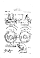
- Figure l is a vertical longitudinal sectional view.
- Fig. 2 is a plan View with the top and the ordinary reproducer removed.
- Fig. 3- is adetail.
- Fig. 4 shows a slight modification.
- Fig. 5 1s a plan view of the form shown in Fig. 4. with top removed.
- Fig. 6 1s an invrtcd fragmentary view of the top shown in Fig. 4.
- 1 designates the diaphragm of an ordinary reproducer of the type employed in connection with the well-known Edison phonograph.
- This diaphragm is covered by a sound wave collector 2 having a ring 3 which encircles and extends beneath the diaphragm, [and also having a tube-like extension4 towhich a flexible tube or a horn may be secured By this device all the sound waves from above formed between ring 12 through the ordinary collector.
- the reproducer as a whole is located Wholly within a casing having a lower chamber 6 beneath the diaphra m and an upper chamber 7,- the two chain ers being in communication with each other but not with the interior of the sound collector 2.
- This casing is shown in Fig.1
- the stylus arm 16 is located beneath the inclosing casing, and is connected in the usual manner to the center of the diaphragm.
- the inclosing casing may be constructed in any preferred manner.
- the ring 8 instead of being formed integral with the bottom member of the casing may be formed independently thereof, as shown at 8 in Fig. 4, and it and the top-piece may be held in place by the screws 17 passed through lugs 13.
- the lugs carrying screws 14 may be smaller and arranged mtermediate the lugs 13*.
- Other chan es may be made without departing from the scope of my invention.
Landscapes
- Diaphragms For Electromechanical Transducers (AREA)
Description
J. GEORIGI. ATTACHMENT FOR PHONOGRAPHS.
. IIIIIIIIIIIIIIIII 0V 7 l 9 0 8.
936,115. '7 Patented 0015.5,1909.
- 'unrran srarns PATENT onion.
.IOHN GEORIGI, F- PHILADELPHIA, PENNSYLVANIA.
ATTACHMENT Foa PHONOGRAPHS.
Specification of Letters Patent.
Patented Oct. 5, 1909.
Application filed November 7,1908. Serial No. 461,518.
to which it appertains to make and use the same.
The primary object of this invention is to provide a simple device for increaslng the .volume of sound waves in reproducers of the upper collector to a common the diaphragm talking machines. Ordinarily the sound waves are collected only from above the diaphragm from which the stylus is suspended, sound from beneath the diaphragm being lost. By means 0" my invention the ordinary diaphragm and the sound wave collector are inclosed in a casing havinga chamber for collecting the sound wavesfrom beneath the diaphragm and transferring them independently of the sound waves of point where the (ZOHJOlIlt sound waves of greatly increased volume may be transmitted through a tube or horn.
A further object of my invention is to provide a device of this character which may be applied to reproduoers 110w in general use.
The invention will be hereinafter fully set forth and particularly pointed out in the claims In the accompanying drawings, Figure l is a vertical longitudinal sectional view. Fig. 2 is a plan View with the top and the ordinary reproducer removed. Fig. 3- is adetail. Fig. 4 shows a slight modification. Fig. 5 1s a plan view of the form shown in Fig. 4. with top removed. Fig. 6 1s an invrtcd fragmentary view of the top shown in Fig. 4.
Referring to the drawings, 1 designates the diaphragm of an ordinary reproducer of the type employed in connection with the well-known Edison phonograph. This diaphragm is covered by a sound wave collector 2 having a ring 3 which encircles and extends beneath the diaphragm, [and also having a tube-like extension4 towhich a flexible tube or a horn may be secured By this device all the sound waves from above formed between ring 12 through the ordinary collector.
are collected.- Ordinarily v .1 thestylus arm is located immediately be- GEORIGI, of:
neath the diaphragm and at one end is connected to the latter at the center thereof.
According to my invention the reproducer as a whole is located Wholly within a casing having a lower chamber 6 beneath the diaphra m and an upper chamber 7,- the two chain ers being in communication with each other but not with the interior of the sound collector 2. This casing is shown in Fig.1
as being composed of a lower cup-like portion having a circumferential ring 8 of reater diameter than the ordinary reproducer, and an upper top-piece 9 terminating in a tubular extension 10 which incloses the tubulancxtension of the ordinary re roducer. The latter is shown as fitted m a ring 12 having a series of peripheral lugs 13 which fit in seats in ring 8. It is held to reproducer 2 by screws 14. The spaces thus and ring 8 of the casing form passage-ways for the sound waves from beneath the diaphragm to the top-piece of the casing. In this way the full volume of sound waves produced by the vibratory action of the diaphragm is collected, the sound waves from beneath the j diaphragm being transferred to a point some distance above the diaphragm before intermingling with the sound waves collected The toppiece 1s shown in Fig. l as being detachably held by retainers 15 secured to ring 8.
In the use of'my invention the stylus arm 16 is located beneath the inclosing casing, and is connected in the usual manner to the center of the diaphragm.
It is manifest that the inclosing casing may be constructed in any preferred manner., For instance, the ring 8 instead of being formed integral with the bottom member of the casing may be formed independently thereof, as shown at 8 in Fig. 4, and it and the top-piece may be held in place by the screws 17 passed through lugs 13. In this form the lugs carrying screws 14 may be smaller and arranged mtermediate the lugs 13*. Other chan es may be made without departing from the scope of my invention.
To those-skilled in the art the advantages of my improvement will be readily appreciated. It may be applied to ordinary reoroducers, of the type now in general use, without necessitating any change in the consound-waves from beneath said diaphragm Wa leadingfrom said chamber to and also an independent assageabout the point of discharge from the first mentionedsound collector.
2. The combination with a reproducer having a vibratory diaphragm, and a soundcollector for receiving all the -sound-waves from above'the diaphragm and discharging the same at a-certam point, of a casing inclosing such diaphragm and sound-collector and having a lower chambered portion for collecting all'the sound-waves from beneath said diaphragm, and a top-piece extendin around said sound-collector, said chambers portion'being in communication with said top-piece, which latter discharges the sound waves from the lower chamber upward beyond the point of discharge from the first mentioned collector.
. 3. The combination with a reproducer having a vibratory diaphragm, and a soundcollector for receiving all the sound-waves from above the diaphragm and concentrating said sound waves at a single point, of a casing inclosing such diaphra m and soundcollector com risin a cham ered portion encircling sai diap ra m, a to piece above said sound-collector, said chain cred portion and top-piece being in communication outdiameter than the 4. The combination with a reproducerc and an imperforate' sound-collector, of a ring secured to the ex-,
having a die ragm terior of said reproducer, a casing in which said ring is mounted having a chambered portion beneath said diaphragm, and a toppiece surrounding said sound-collector, said chambered portion bein in communication with said top-piece on t e outside of the re producer. I
5.. The combination with a reproducer having a vibrato diaphra m and a soundcollector for receivin all the sound waves from above the diap ragm, said collector having a tubular extension, of a. casing inclosing said reproducer and having a chamber for collecting-all the sound-waves from beneath said diaphragm, and a top-piece having a tubular extension surrounding the tubular extension of the sound-collector, said chamber and topiece being in communication with each otier. I
6. The combination with a reproducer having a diaphra in and a sound-collector, of a ring secure to said reproducer and having a series of lugs rojecting therefrom, a casing having arin ike portion of greater rst mentioned ring, a top-piece surrounding said sound-collector, and means for securing said top-piece.
In testimony whereof, I have signed this specification in the presence of two subscribing witnesses.
JOHN GEORIGI.
-Witnesses GODFREY S. Tnnismv, PATRICK J. OBnmn.
Priority Applications (1)
| Application Number | Priority Date | Filing Date | Title |
|---|---|---|---|
| US46151808A US936115A (en) | 1908-11-07 | 1908-11-07 | Attachment for phonographs. |
Applications Claiming Priority (1)
| Application Number | Priority Date | Filing Date | Title |
|---|---|---|---|
| US46151808A US936115A (en) | 1908-11-07 | 1908-11-07 | Attachment for phonographs. |
Publications (1)
| Publication Number | Publication Date |
|---|---|
| US936115A true US936115A (en) | 1909-10-05 |
Family
ID=3004537
Family Applications (1)
| Application Number | Title | Priority Date | Filing Date |
|---|---|---|---|
| US46151808A Expired - Lifetime US936115A (en) | 1908-11-07 | 1908-11-07 | Attachment for phonographs. |
Country Status (1)
| Country | Link |
|---|---|
| US (1) | US936115A (en) |
-
1908
- 1908-11-07 US US46151808A patent/US936115A/en not_active Expired - Lifetime
Similar Documents
| Publication | Publication Date | Title |
|---|---|---|
| US2295483A (en) | Loudspeaker | |
| US2252846A (en) | Acoustic device | |
| US2399513A (en) | Piezoelectric transducer | |
| US2238741A (en) | Electrodynamic transducer | |
| US2835735A (en) | Anti-shock transducer | |
| US1871253A (en) | Sound reproducing apparatus | |
| US1372862A (en) | Transmitter | |
| US2250781A (en) | Microphone | |
| US2560354A (en) | Close taling microphone | |
| US1296683A (en) | Telephone-transmitter. | |
| US1231095A (en) | Telephone-transmitter. | |
| US2847520A (en) | Damped microphone | |
| US2179733A (en) | Microphone | |
| US1025992A (en) | Transmitter for telephonic or audiphonic systems. | |
| US2288839A (en) | Sound translating device | |
| US2331044A (en) | Sound translating device | |
| US1111779A (en) | Phonographic sound-box. | |
| US1105066A (en) | Telephonic transmitter. | |
| US1559847A (en) | Electrical transmission or reproduction of sound | |
| US1045968A (en) | Telephone-transmitter. | |
| US1640330A (en) | Diaphragm for telephonic apparatus | |
| US792927A (en) | Telephone-transmitter. | |
| US1408776A (en) | Sound box for talking machines | |
| US1570662A (en) | Sound-wave-intensifying device for reproducers | |
| US572188A (en) | Louis d |