US935914A - Jar for well-drills. - Google Patents
Jar for well-drills. Download PDFInfo
- Publication number
- US935914A US935914A US44113308A US1908441133A US935914A US 935914 A US935914 A US 935914A US 44113308 A US44113308 A US 44113308A US 1908441133 A US1908441133 A US 1908441133A US 935914 A US935914 A US 935914A
- Authority
- US
- United States
- Prior art keywords
- stem
- drill
- jar
- springs
- head
- Prior art date
- Legal status (The legal status is an assumption and is not a legal conclusion. Google has not performed a legal analysis and makes no representation as to the accuracy of the status listed.)
- Expired - Lifetime
Links
- 239000011435 rock Substances 0.000 description 3
- 238000005553 drilling Methods 0.000 description 2
- 239000004927 clay Substances 0.000 description 1
- 230000008878 coupling Effects 0.000 description 1
- 238000010168 coupling process Methods 0.000 description 1
- 238000005859 coupling reaction Methods 0.000 description 1
- 239000007789 gas Substances 0.000 description 1
- 229910052500 inorganic mineral Inorganic materials 0.000 description 1
- 239000007788 liquid Substances 0.000 description 1
- 239000011707 mineral Substances 0.000 description 1
- 239000003973 paint Substances 0.000 description 1
- 229920000136 polysorbate Polymers 0.000 description 1
- 230000001105 regulatory effect Effects 0.000 description 1
- 239000004576 sand Substances 0.000 description 1
- 230000035939 shock Effects 0.000 description 1
- 239000007787 solid Substances 0.000 description 1
- 239000000126 substance Substances 0.000 description 1
- -1 through loam Substances 0.000 description 1
- XLYOFNOQVPJJNP-UHFFFAOYSA-N water Substances O XLYOFNOQVPJJNP-UHFFFAOYSA-N 0.000 description 1
Images

Classifications
-
- E—FIXED CONSTRUCTIONS
- E21—EARTH OR ROCK DRILLING; MINING
- E21B—EARTH OR ROCK DRILLING; OBTAINING OIL, GAS, WATER, SOLUBLE OR MELTABLE MATERIALS OR A SLURRY OF MINERALS FROM WELLS
- E21B31/00—Fishing for or freeing objects in boreholes or wells
- E21B31/107—Fishing for or freeing objects in boreholes or wells using impact means for releasing stuck parts, e.g. jars
Definitions
- This inventlon relates to a device which is designed to be used with any type of drilling l dri apparatus and any form o l for boring holes for plunger elevator shafts or shafts for other purposes, or deep or shallow wells for water, oil or other liquid, gas or minerals, through loam, sand, clay, gravel orvboulders, ledge or solid rock, for the purpose of keeping the drill vertical so that the hole will be straight and plumb, and for loosening the drill in case it becomes jammed or other- Y wise fastened in the hole.
- the object of this inventon is t'o produce a simple device which is readily connected in the string between the drill and the lifting rod or cable, and which can be easily adJusted to fit a hole of any usual size so that it will keep the drill stralght, and which is so constructed that tions it is rigid, and rovides a firm' connection between the dr' and the liftin means, and yet if the drill becomes jamme or fastened in the hole, its stem is released from the body ofthe device so that it may be .used to jar the drillloose.
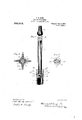
- Figure 1 of the accom anying drawings shows a side elevation otp the jar in condition for use, that is, A rigidly connected so that they act as one piece.
- Fig. 2 is a similar view of the same turned one eighth wa around
- Fig. 3 is an elevation with the bo y cutY in central section so as to e osethe yielding means which connect the ody and the stem.
- Fig. 4 shows a side view of the stem and the vupper portion of. the bod with the parts yin the rela .tion assumed a er the stem has been loosened fr om the body and is free to' jar the-drill.
- Flg. 5 1s a transverse section taken on the plane indicated by the dotted line 5 5 on.
- Flg. 6 is a section taken on the lane in icated by the dotted line 6 6 on F1 4.
- the body 1 of this jar is tubular.
- acter is' adapted to be screwed.
- Set in the upper end of the head in the body is a removable anvil block 5 and in mortises in thev sides of the head andextending into the body are heavy leaf springs 6.A These springs are preferably secured in place by blocks 7 which are free to move in the mortises and are adjustably held by lscrews 8 that extend through' slots 9 in these blocks (Fig. 3). The free ends of these springs rest'against the linner walls of the tubular body, ⁇ and beare blocks are holding shoulders 10.
- the stem 11 of the jar at its up er end has a thread 12 which is adapte to be screwed" intoy the coupling which connects the jar with the lifting rod or cable, and below the threaded end 1s a'squared section 13 for the application of a ⁇ Wrench which may be used for screwing the' parts together.
- the lower end of the head is pre erably tapered on the sides so 'that it will readily pass betweenA the and when the end 'of the anvil .block 5, the shoulders of the springs engage the shoulders of the lhead and hold the stem and body together as one ieee.
- the head rests upon in jectingsides of the head l Y
- the springs' engage the head which the prol5 on its upper ed e.
- the additional strain which is thusy caused is sullicient to pull the head from the springs and allow the stem to 'lift freely, the head of the stem drawing .up in the groovesl in This instantly relieves the hoisting machinery and the engine so that they are not suddenly stopped, which stopping is likely to damageA or break some of the parts of the apparatus or the engine.
- the stem is released in this manner lb by the jamming o the drill thel stem is llfted to the upper part of thetubular body as shown in Fig. 4 and drawn up and down so that thehead ofthe stem will -knock with an upward motion against the flange 18' around the interior of the upper part of the tubular body.
- Flanges 22 may be cast integralwith' or otherwise secured to the outer wall of the to .the tubular bo guiding tubular body. These ilanges, of which four are shownin the drawing, ma be secured tothe body by collars 23 at their upper and lower ends, which are fastened by any suitable means. It is desirable to make these flanges with mortises in which can be placed win 24.
- wings of the proper size may be inserted in the mortises in the flanges so as to bear against thek walls of the opening or the casing in necessity for the class of drilling for which,
- a drill jar having a body adapted to be connected with a drill, a stem adapted to be connected with a lifting apparatus, means permanently attached to one part and yieldingly connected with the other part whereby theparts are raised as one piece under normal strain, but automatically ⁇ freed when the upward strain is excessive, and means ar. ranged on one part and adapted to engage means on the other part to prevent the complete se'paration of the parts, substantially as specified.
- a drill jar having a body adapted to be connected with adrill, a stem adapted to be connected with a lifting apparatus, springs permanently connected with one part and -yieldingly engagin the other art whereby the parts are norma ly connecte together by said springs, and means for adjusting the ersion of the. springs, substantially as speci- 3.
- a drill jar having a body adapted to be .I
- a drill jar having a tubular. body adapted to be connectedwith a drill, a cylindrical stem adapted to be connected wlth a lifting means, said stem having shoulders near its lower end, leaf springs connected with the body and having shoulders adapted f to engage the shoulders on the stem, substantiallyas specified.
- a drill jar having a tubular body adapted to be connected with a drill, a cylindrical stem adapted to be connected with a lifting means, said stem having shoulders, leaf springs connected with the body, said springs havin Ishoulders adapted to engaI e the shoul ers on thestem, and-means or adjusting the tension of the springs, substantially as specified.
- a drill-jar havin a body ada ted to be connected with a dr' l, a stem adapted to be connected with ⁇ a lifting apparatus, springs permanently attached to one part and yieldingly engagingthe other part so as.
- a drill jar having a. body adapted to be l ing longitudinal recesses end Wings remov connected with a drill, a stem adapted to be i ably secured in said recesses and projecting connected with a lifting apparatus, springs from the flanges, substantially as specified. 10
Landscapes
- Life Sciences & Earth Sciences (AREA)
- Engineering & Computer Science (AREA)
- Geology (AREA)
- Mining & Mineral Resources (AREA)
- Marine Sciences & Fisheries (AREA)
- Physics & Mathematics (AREA)
- Environmental & Geological Engineering (AREA)
- Fluid Mechanics (AREA)
- General Life Sciences & Earth Sciences (AREA)
- Geochemistry & Mineralogy (AREA)
- Earth Drilling (AREA)
Description
H. B. KING. y POB.
IIIIIIIIIIIIIIIIIIIIIIIIIII 8.
SSSSSSSSSSSS 1.
, iniill'll.
am 'um Ullmann i; ffmuwm i /f Ulu ii U llIllllll 1 lllllllll IIIIII u l Y ll f @Zi/g,
H. B. KING.
JAR FOR WELL DRILLS.
APPLICATION FILED JUNE 3o. 190s.
935,914.v Y Patented 0cm, 1909.
2 SHEETB-SHEET 2.
HARVEY B. KING, 0F HARTFORD, CONNECTICUT, ASSIGNOR HARTFORD, CGNNECTICT.
erica.
To FRANK J. intox, .or
- y JAR .Foa WELL-paints.
Specication oi.' Letters Patent.
Patented Get. 5,1909.
Application inea June so, 190s. .serial No. 441,133.
To all whom it may concern:
Be it known that I, HARVEY B. t
a Hartford, in the county of Hartford and State of Connecticut, have-invented a new and useful Jar for VVell-Drills, of' which the following is a specification.
This inventlon relates to a device which is designed to be used with any type of drilling l dri apparatus and any form o l for boring holes for plunger elevator shafts or shafts for other purposes, or deep or shallow wells for water, oil or other liquid, gas or minerals, through loam, sand, clay, gravel orvboulders, ledge or solid rock, for the purpose of keeping the drill vertical so that the hole will be straight and plumb, and for loosening the drill in case it becomes jammed or other- Y wise fastened in the hole. Y v
The object of this inventon is t'o produce a simple device which is readily connected in the string between the drill and the lifting rod or cable, and which can be easily adJusted to fit a hole of any usual size so that it will keep the drill stralght, and which is so constructed that tions it is rigid, and rovides a firm' connection between the dr' and the liftin means, and yet if the drill becomes jamme or fastened in the hole, its stem is released from the body ofthe device so that it may be .used to jar the drillloose.
Figure 1 of the accom anying drawings shows a side elevation otp the jar in condition for use, that is, A rigidly connected so that they act as one piece.l Fig. 2 is a similar view of the same turned one eighth wa around, Fig. 3 is an elevation with the bo y cutY in central section so as to e osethe yielding means which connect the ody and the stem.. Fig. 4 shows a side view of the stem and the vupper portion of. the bod with the parts yin the rela .tion assumed a er the stem has been loosened fr om the body and is free to' jar the-drill. Flg. 5 1s a transverse section taken on the plane indicated by the dotted line 5 5 on.
rg. 2. Flg. 6 is a section taken on the lane in icated by the dotted line 6 6 on F1 4. The body 1 of this jar is tubular. ast
. inte al wlth or otherwise firmly secured to the ower end of the bod y (1, luto w ich the stem of a is a head 2 which has a s uare neck 3 an drill of any'char- KING, a l' citizenof the United States, residing 'tween the free ends andlwhere they held b By sli ing under ordinary condiwith the stem and body' -stuck in the hole as by the a threaded sockety the body withoutlifting thebody.
acter is' adapted to be screwed. Set in the upper end of the head in the body is a removable anvil block 5 and in mortises in thev sides of the head andextending into the body are heavy leaf springs 6.A These springs are preferably secured in place by blocks 7 which are free to move in the mortises and are adjustably held by lscrews 8 that extend through' slots 9 in these blocks (Fig. 3). The free ends of these springs rest'against the linner walls of the tubular body,`and beare blocks are holding shoulders 10.
these blocks upwardly or downwardly the stiffness of these springs that is, the strength of their holdrcan be regulated.
The stem 11 of the jar at its up er end has a thread 12 which is adapte to be screwed" intoy the coupling which connects the jar with the lifting rod or cable, and below the threaded end 1s a'squared section 13 for the application of a `Wrench which may be used for screwing the' parts together. The cylindrical stem lits the inner walls of the cylindrical body, the stem is provided projects outwardly in two directions so as to form shoulders the sides of the stem head are sho ders 16 which are adapted to be'- engaged by the shoulders lO'of the 's' rings 6. The lower end of the head is pre erably tapered on the sides so 'that it will readily pass betweenA the and when the end 'of the anvil .block 5, the shoulders of the springs engage the shoulders of the lhead and hold the stem and body together as one ieee.
the head rests upon in jectingsides of the head l Y When the device is operatlng under normal conditions', the springs' engage the head which the prol5 on its upper ed e. On'
`springs when it is dropped downwardly,-
In the walls of the tubular body are 1 A ongitudinal grooves 17 and hold the stem and bodyv of the 'ar so that it lifts and drops as one piece.- the drill fon any reason becomes, jammed or dropping in of pieces of rock or other matter,
and' it re`4 quires an excessive force to release the drill,
the additional strain which is thusy caused is sullicient to pull the head from the springs and allow the stem to 'lift freely, the head of the stem drawing .up in the groovesl in This instantly relieves the hoisting machinery and the engine so that they are not suddenly stopped, which stopping is likely to damageA or break some of the parts of the apparatus or the engine. When the stem is released in this manner lb by the jamming o the drill thel stem is llfted to the upper part of thetubular body as shown in Fig. 4 and drawn up and down so that thehead ofthe stem will -knock with an upward motion against the flange 18' around the interior of the upper part of the tubular body. The' knocking of the shoulders 15 againstithe bottom edge 19 of this flange -jars the drill loose without putting undue strain upon the apparatus. Grooves 20 are made through this ange at the upper end of .the tublar'body for the purpose of allowing the heady of4 the stem to enter the body. The stem is inserted into the body with its head in these grooves and lowered until the head reaches the opening 21 at the lower end of the tubular body, then the stem isturned one-quarter Way around .and the head drawn intothe grooves 17, after `which the anvil block 5 is placed in position vso that the stem cannot drop low enough for the head toturn around and get out of 'these grooves.
I the jar is as busiea aigu-ning a dan in a relatively small Well hole, `it ma be.
used Without the flanges and wings. f it is to be used for a large well hole or a small elevator shaft hole the flan es may be added d ,andi iris to be used for an extra large hole, as for a large elevator plunger or other purpose, wings of the proper size may be inserted in the mortises in the flanges so as to bear against thek walls of the opening or the casing in necessity for the class of drilling for which,
this jar is designed. w v
. The parts work together as one piece when the too s are operating under normal conditions, for the s rings are adjusted to keep the parts .together under normal "strain,
Should-the drill become 'jammed or cramped excessive strain, causedby reason of. the dropping in of pieces of rock or other substance so that it could not be lifted with the usual force and anabnormal strain is brought upon the parts, the springs release the stem and relieve the machney of shock and then the stem is used to jar the drill loose. After the drill has been loosened, the stem is dropped'until its head is again engaged by the springs, after' which the norma operation'is resumed.
The invention claimed is: v v
1. A drill jar having a body adapted to be connected with a drill, a stem adapted to be connected with a lifting apparatus, means permanently attached to one part and yieldingly connected with the other part whereby theparts are raised as one piece under normal strain, but automatically` freed when the upward strain is excessive, and means ar. ranged on one part and adapted to engage means on the other part to prevent the complete se'paration of the parts, substantially as specified.
2. A drill jarhaving a body adapted to be connected with adrill, a stem adapted to be connected with a lifting apparatus, springs permanently connected with one part and -yieldingly engagin the other art whereby the parts are norma ly connecte together by said springs, and means for adjusting the ersion of the. springs, substantially as speci- 3. A drill jar having a body adapted to be .I
connected withja drill, a stem adapted )to be connected with a lifting apparatus, springs connected withthe body and adapted to engage the stem and normally connect the bo y and thestem, and means for adjusting the tension of the springs, substantially as specified. ,f
4. A drill jar having a tubular. body adapted to be connectedwith a drill, a cylindrical stem adapted to be connected wlth a lifting means, said stem having shoulders near its lower end, leaf springs connected with the body and having shoulders adapted f to engage the shoulders on the stem, substantiallyas specified.
5. A drill jar having a tubular body adapted to be connected with a drill, a cylindrical stem adapted to be connected with a lifting means, said stem having shoulders, leaf springs connected with the body, said springs havin Ishoulders adapted to engaI e the shoul ers on thestem, and-means or adjusting the tension of the springs, substantially as specified.
6. A drill-jar havin a body ada ted to be connected with a dr' l, a stem adapted to be connected with `a lifting apparatus, springs permanently attached to one part and yieldingly engagingthe other part so as.
to'normally connect the parts together, and ianges .extendin body, substantial y as specified.
from the exterior of the 7. A drill jar having a. body adapted to be l ing longitudinal recesses end Wings remov connected with a drill, a stem adapted to be i ably secured in said recesses and projecting connected with a lifting apparatus, springs from the flanges, substantially as specified. 10
e permanently connected with one part and HARVEY B. KING. 5 yieldingly engaging the other part so as to TWitnesses: i normally connect the .parts together, flanges JOSEPHINE M. STREMPFER,
project-ing from the body7 said flanges hav- HARRY R. WILLIAMS.
Priority Applications (1)
| Application Number | Priority Date | Filing Date | Title |
|---|---|---|---|
| US44113308A US935914A (en) | 1908-06-30 | 1908-06-30 | Jar for well-drills. |
Applications Claiming Priority (1)
| Application Number | Priority Date | Filing Date | Title |
|---|---|---|---|
| US44113308A US935914A (en) | 1908-06-30 | 1908-06-30 | Jar for well-drills. |
Publications (1)
| Publication Number | Publication Date |
|---|---|
| US935914A true US935914A (en) | 1909-10-05 |
Family
ID=3004336
Family Applications (1)
| Application Number | Title | Priority Date | Filing Date |
|---|---|---|---|
| US44113308A Expired - Lifetime US935914A (en) | 1908-06-30 | 1908-06-30 | Jar for well-drills. |
Country Status (1)
| Country | Link |
|---|---|
| US (1) | US935914A (en) |
-
1908
- 1908-06-30 US US44113308A patent/US935914A/en not_active Expired - Lifetime
Similar Documents
| Publication | Publication Date | Title |
|---|---|---|
| US3835943A (en) | Drilling apparatus and adaptor assembly for such apparatus | |
| US20160362943A1 (en) | Drill string component coupling device | |
| US1776776A (en) | Liner setter and puller | |
| US2945678A (en) | Bottom hole drilling fluid control valve | |
| US2474459A (en) | Jar | |
| US1918096A (en) | Method and apparatus employed in the drilling of wells | |
| US1873814A (en) | Coupling for drill bits | |
| US2146454A (en) | Vibrating well jar | |
| US2572895A (en) | Safety sub jar assembly | |
| US2021184A (en) | Drilling structure and bit | |
| US3360047A (en) | Well drilling device | |
| US1866943A (en) | Percussive well drilling apparatus | |
| US1011324A (en) | Well-drilling apparatus. | |
| US2189923A (en) | Coring and drilling device | |
| US1667077A (en) | Drill | |
| US1523928A (en) | Liner setting tool and safety joint | |
| US1647240A (en) | Well-drilling tool | |
| US529781A (en) | Per anton ceaelius | |
| US1545830A (en) | Eccentric combination socket | |
| US1747020A (en) | Jar | |
| US1855363A (en) | Drilling tool joint | |
| US1962589A (en) | Drill bit | |
| US1776594A (en) | Centralizer for drill steels | |
| US2562320A (en) | Torque controlled well jar | |
| US261841A (en) | Tubular rock-drill |