US935729A - Bag-folding machine. - Google Patents
Bag-folding machine. Download PDFInfo
- Publication number
- US935729A US935729A US35784607A US1907357846A US935729A US 935729 A US935729 A US 935729A US 35784607 A US35784607 A US 35784607A US 1907357846 A US1907357846 A US 1907357846A US 935729 A US935729 A US 935729A
- Authority
- US
- United States
- Prior art keywords
- bag
- folding
- machine
- blades
- chains
- Prior art date
- Legal status (The legal status is an assumption and is not a legal conclusion. Google has not performed a legal analysis and makes no representation as to the accuracy of the status listed.)
- Expired - Lifetime
Links
- 239000000969 carrier Substances 0.000 description 11
- 229910003460 diamond Inorganic materials 0.000 description 6
- 239000010432 diamond Substances 0.000 description 6
- 238000010276 construction Methods 0.000 description 2
- 230000007246 mechanism Effects 0.000 description 2
- 230000000630 rising effect Effects 0.000 description 2
- 238000005266 casting Methods 0.000 description 1
- 230000000881 depressing effect Effects 0.000 description 1
Images



Classifications
-
- B—PERFORMING OPERATIONS; TRANSPORTING
- B31—MAKING ARTICLES OF PAPER, CARDBOARD OR MATERIAL WORKED IN A MANNER ANALOGOUS TO PAPER; WORKING PAPER, CARDBOARD OR MATERIAL WORKED IN A MANNER ANALOGOUS TO PAPER
- B31B—MAKING CONTAINERS OF PAPER, CARDBOARD OR MATERIAL WORKED IN A MANNER ANALOGOUS TO PAPER
- B31B70/00—Making flexible containers, e.g. envelopes or bags
- B31B70/26—Folding sheets, blanks or webs
- B31B70/52—Folding sheets, blanks or webs by reciprocating or oscillating members other than plungers and dies, e.g. by fingers
-
- B—PERFORMING OPERATIONS; TRANSPORTING
- B31—MAKING ARTICLES OF PAPER, CARDBOARD OR MATERIAL WORKED IN A MANNER ANALOGOUS TO PAPER; WORKING PAPER, CARDBOARD OR MATERIAL WORKED IN A MANNER ANALOGOUS TO PAPER
- B31B—MAKING CONTAINERS OF PAPER, CARDBOARD OR MATERIAL WORKED IN A MANNER ANALOGOUS TO PAPER
- B31B2150/00—Flexible containers made from sheets or blanks, e.g. from flattened tubes
-
- B—PERFORMING OPERATIONS; TRANSPORTING
- B31—MAKING ARTICLES OF PAPER, CARDBOARD OR MATERIAL WORKED IN A MANNER ANALOGOUS TO PAPER; WORKING PAPER, CARDBOARD OR MATERIAL WORKED IN A MANNER ANALOGOUS TO PAPER
- B31B—MAKING CONTAINERS OF PAPER, CARDBOARD OR MATERIAL WORKED IN A MANNER ANALOGOUS TO PAPER
- B31B2160/00—Shape of flexible containers
- B31B2160/20—Shape of flexible containers with structural provision for thickness of contents
Definitions
- This invention relates to machines for forming from paper tubing square bottom or self opening bags. My endeavor in the invention has been to devise a better construction of such machines ⁇ than has been used before, and one which will be certain,
- a leading feature of the invention is found in the manner of supporting the folding'devices. These devices are mounted upon endless chains or carriers and in such number as desired, and they may be arranged on the chains as close together as the length of the bags will permit so that no loss of -time will occur between successive bags, and while they are operating on the bags they move forward in a straight horizontal path and at a uniform speed.
- the nature of my improvement by which these ends areattained, is fully disclosed in the subjoined description, and illustratedin the accompanying drawings forming a part of such description.
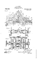
- Figure 1 is a side elevation of the machine, Fig; 2 a central vertical section, Fig. 3 a section on the line 3-3 of Fig. l, Fig. 4 a sectiony on the line 4-4 of Fig. 3.
- Figs. 5, 6 and 7 are enlarged vertical sections of one of.l the folding mechanismsshowing it in different stages of its operation.
- Fig. 11 is a vertical section of the pasting and creasing devices.
- 13 are sections on the lines 12-12 and 13--13 respectively of Fig. 11.
- Figs. 14, 15 and 16 are perspective views showing the different stages of the folding operation.
- Fig. 17 is a perspective view showing the pasting operation.
- 2() indicates the side frames, and 21 the pulley driven shaft by which the machine is actuated.
- This shaft carries a pinion 22 meshing with Figs. 12 and .having'a bevel pinion 38 at lits farther end driving a second pinion 39 on the journal 10 of the lower one of a pair of feed rolls 41, having intermeshing gears 4:2 whereby the lower roll drives the upper one.
- These rolls receive the flattened tubular paper blanksX from which the bags are formed, and feed to the holding mechanism of the machine, passing them firstv between small pressure rolls 43 driven by suitable gearing shown at Fig. 2, from the lower feed roll 41.
- the upper chains 32 ride upon the sprocket- 31 at one end and upon a second sprocket 51 at the other end, and although shorter than chains 26, they-move at the same speed there- 'A with, and carry portions of the folding mech-v anisms which coact with the portions car ried upon chains 26 as will now'be seen.
- a pair of folding blades 54 is provided at each side of the mach-ine, and each pair is hinged upon a pivot 55 supported from one of the castings 53h as seen a ⁇ t Figs. 9 and.10, the blades being vindependent of each other and turning in opposite directions away from each other. In their normal ositions the blades stand horizontally side by side and close together as best seen at Figs.
- the blades are actuated in giving the box form to the bag as follows:
- Each blade carries an arm 58, armed with an anti-friction roller, .and of 'said arms, those which are uppermost when the blades are engaged with the bag, encounter and are-swung by cam tracks 59, and those which are lowermost by cam tracks 60.
- cam tracks 59 those which are lowermost by cam tracks 60.
- the blades are opened or spread as. already stated, and they retain their changed ositions until withdrawn laterally as descri ed below.
- a pair of side wings 61 pivoted in lateral projections 62v upon the plate 53 and normally positioned at right an les to the plates, are caused to swing towar each other and down flatwise upon the plate, thereby fiattening the box and putting it into position for' pasting.
- the wings 61 are actuated in this position as follows:
- Each of the wings has a 'projecting arm 63, provided with an anti-frlctionroller, and said rollers while the supporting plate 53 is movin through the lower portion of its path eac come in,
- the wings 61 are required to maintain pressure on the, bag but a short time, and
- cams 64 therefore recede from each other as at Fig. 4, and allow the wings to gradually resume their normal positions, they be ing furnished with springs encircling'their pivots, for causing their return.
- the diamond folders 54 while acting move in a' plane nearer the central longitudinal line of the machine, than --while moving idly through the remainder of their path, and they are shifted in and out by cams 70,
- the chain 26 which continues its horizontal movement past the pasting, creasing and finalfolding mechanisms, now carries the' bag first under the pasting roller 72 best shown at Fig. 11 which is supplied with paste by the feed roller 73 rotating in the paste dish 74.
- the roller 73 is rotated from the sprocket 33 and shaft 34 by gear 75, and intermediate 76.4,
- the creaser 77 is carried on shaft 34 and consists of two disks 7'8- rotating with theshaft and having radial slots 7 9 in which are placed creaser blades 80.
- the ends of the blades have projecting rollers 81 which ride on cams 82 formed in the depending brackets 83 located at either end of the creaser, and
- the clip 65 is lifted by a second pin 87, similar to pin 68, and located as shown atl Figs. 2 and 11 so that both'the flap ends are then free to be folded over on to the central part of the bottom.
- the creaser leaves the ends in such condition that they will be laid over one on top of the other on the central portion, by the Iiipper 88 uponthe shaft 89 and the pressure rollers 90 and 91.
- the shaft 89 is rotated by'its gear 92 andthe intermediate 93 from the gear 75 and in order to avoid intepference with roller 90 by the flipper, said ⁇ roller is made in two parts or sections, eac'h having its own bearing, and its own actuating means.
- one part of the roller is operated by pinion 94 meshing with pinion 95 on the shaft of roller 91 and taking power from gear'92, while the other part of roller 90 is operated by pinions/QG and 97, the former upon the shaft of roller 91.
- the bag moves over a platform 98, and after passing the rollers slidesdow-n a table 99 onto'a conveying belt 100 and are carried -into the bight of that belt and a second similar belt.
- the rollers 90 and 91 complete 'the bag.
- nippers mounted upon each cross bar 450. They' are adapted to take hold o f the edge of the body of the bag, and are pivoted on the cross bars 450 held in acting position by springs as shown. They are raised to allow them to nip the bag by stationary cams after the bag has-passed into the control of platesl 47 and of the clips on such plates, and they are also raised to release the bag after it' has been creased, so as to pass between the pressure rolls 90 and 91.
- the cams referredv to for thus operating the nippers are shown in pairs at 105 andu106 (see Fig. 13).
- the upper carrier having a stationary plate forming part of the folding bed
- the lower carrier having a hinged plate also forming a part of the folding bed, means for operat ⁇ ing said hinged. plate, and means for folding the blanks; said bed plates supporting the bag blanks during 'the folding operations, and said ⁇ hinged plate rising to an upright position to receive fresh blanks ⁇ and falling to position them for pasting.
- the upper carrier having a stationary plate 4 forming part of the folding bed
- the lower carrier having a hinged plate also forming a part ofthe foldingbed, means for operating said hinged plate and means for folding the blanks, said bed plates supporting the bag blanks during the folding operations, and said hinged plat rising to an upright position to receive fresh blanks and falling to position them for pasting, and a paste roller acting on the folded blank.
Landscapes
- Folding Of Thin Sheet-Like Materials, Special Discharging Devices, And Others (AREA)
Description
T. M. AVERY. BAG FOLDING MACHINE. APPLIOATION FILED 33.18. 1907.
Patented 0ct.5, 1909.
8 SHEETS-SHEET l.
T. M. AVERY.
BAG FOLDING MACHINE.
APPLICATION FILED FEB.18, 1907,
figg/UWM@ Q .w 0 f n n o n D mm d wm @www h Q No m. Nw@ m \M A.. fw/ 9. m o w 2 L c.. n o c o o J 7., Nn Nm N .7 MAOU 1 9 QM p y w 9. 2. f f. Ou E U ...n m4 Q m 5 Q a M .n w ,fM p. j mv H nu DEED wma J v. d im DIW no .T C l n 7 M M .m Dnm 5N QN N a D o l Allin c a .o @Si mx 5%..
T. M. AVERY.
BAG FOLDING MACHINE.
APPLICATION FILED IEB.18, 1907. 935,729. Patented 001;. 5, 1909,
8 SHEETS-SHEET 3.
y r M4 y T. M. AVERY. BAG FOLDING MACHINE. AFPLIOATION FILED 12133.18, 1907.
Patented Oct. 5, 1909.
8 SHEETS-SHEET 4.
T. M. AVERY. BAG FOLDING MACHINE. APPLIGATION FILED 113.18, 1907.
Patented 01;.5,1909.
8 SHEETS-SHEET 5.
ggf
T. M. AVERY. -BAG FOLDING MACHINE.
` .APPLIUATION FILED FEB.18, 1907. 935 ,729. Patented Oct. 5, 1909.
8 SHEETS-SHEET 6.
T. M. AVERY.
BAG FOLDING MACHINE.
APPLIOATION FILED PBBJB, 1907.
935,729. Patented 0n.5,1909.
, 8 SHEETS-SHEET 7. i257. f/
ifa /04 l |369 45 8 SHEETS-SHEET B.
True Mvefy L/ewkvm Patented 001.5, 1909.l
T. M. AVERY.
BAG FOLDING MACHINE. APPLIOATION FILED rms 1s 19o? unfailing and speedy in its action, so that UNiTED STA-rus PATENT orrrou.
TRUE M. AVERY, 0F C)'.CIUDIlIVSZA, IOWA, ASSIGNOR, BY MESNE ASSIGNMENTS, lTO UNION PAPER BAG MACHINE COMPANY, OF PHILADELPHIA, PENNSYLVANIA, A COR- PORATION 0F PENNSYLVANIA.
BAG- FOLDING MACHINE.
Specication of Letters atent.
Application filedV February 18, 1907. Serial No. 357,846.
To all whom' it may concern:
Be it known that I, TRUE M. AVERY, a citizen of the United States, residing in 0ttumwa, in the county of Viapello and State of Iowa, have invented a new and useful Improvement in Bag-Foldingh/Iachines, of which the following is a specification.
This invention relates to machines for forming from paper tubing square bottom or self opening bags. My endeavor in the invention has been to devise a better construction of such machines` than has been used before, and one which will be certain,
its capacity will be increased from` that of previous constructions, and which will be simple and little likely to get out of order.
A leading feature of the invention is found in the manner of supporting the folding'devices. These devices are mounted upon endless chains or carriers and in such number as desired, and they may be arranged on the chains as close together as the length of the bags will permit so that no loss of -time will occur between successive bags, and while they are operating on the bags they move forward in a straight horizontal path and at a uniform speed. The nature of my improvement by which these ends areattained, is fully disclosed in the subjoined description, and illustratedin the accompanying drawings forming a part of such description.
In such drawings, Figure 1 is a side elevation of the machine, Fig; 2 a central vertical section, Fig. 3 a section on the line 3-3 of Fig. l, Fig. 4 a sectiony on the line 4-4 of Fig. 3. Figs. 5, 6 and 7 are enlarged vertical sections of one of.l the folding mechanismsshowing it in different stages of its operation. Figs. 8, 9, 10 'are sections on the lines8-8, 9*.9 and 10-10 respectively of Fig. 7. Fig. 11 is a vertical section of the pasting and creasing devices. 13 are sections on the lines 12-12 and 13--13 respectively of Fig. 11. Figs. 14, 15 and 16 are perspective views showing the different stages of the folding operation.
Fig. 17 is a perspective view showing the pasting operation. A
Referring to vsaid drawing, 2() indicates the side frames, and 21 the pulley driven shaft by which the machine is actuated. This shaft carries a pinion 22 meshing with Figs. 12 and .having'a bevel pinion 38 at lits farther end driving a second pinion 39 on the journal 10 of the lower one of a pair of feed rolls 41, having intermeshing gears 4:2 whereby the lower roll drives the upper one. These rolls receive the flattened tubular paper blanksX from which the bags are formed, and feed to the holding mechanism of the machine, passing them firstv between small pressure rolls 43 driven by suitable gearing shown at Fig. 2, from the lower feed roll 41.
' shaft and thus swing the plate from its normal position in which it is parallel to the chains, to an upright or vertical position, at right angles to the plane of the chains. lThe plates continue in this raised condition so iong as their arms 48 remain on cam 49 and swing back to normal pcsition as soon as the arms have passed off the cam, under the power of springs 50. r1`hree ofthe plates are shown as thus raised in Fig. 2.
The upper chains 32 ride upon the sprocket- 31 at one end and upon a second sprocket 51 at the other end, and although shorter than chains 26, they-move at the same speed there- 'A with, and carry portions of the folding mech-v anisms which coact with the portions car ried upon chains 26 as will now'be seen.
` They are connected to each other vat suitable rateneeuoet. 5, ieee.
intervals by cross` bars 52 to each ofswhich is rigidly attacheda plate 53 in a vertical position relative to the chains. The plates 53 lof sliding but prevented from turning by keys 53d let into key ways 53C and held on the arms by set screws 53e. A pair of folding blades 54 is provided at each side of the mach-ine, and each pair is hinged upon a pivot 55 supported from one of the castings 53h as seen a`t Figs. 9 and.10, the blades being vindependent of each other and turning in opposite directions away from each other. In their normal ositions the blades stand horizontally side by side and close together as best seen at Figs. 5 and 14, to adapt them y to enter the'longitudinal side folds of the bagblank, as shown at Fig. 14. After being thus entered in the side folds, the blades yare turned in diverging directions on their? -axis from the position of Figs. 5 and 14 to that of Figs. 6 and 15. In this change they assumel vertical positions, parallel to the plates 47 and 53, and also move bodily away from each other, as shown, and in so doing they. open the end of the bag into the open box form -seen at Figs. 6 and `15 and form the diamond folds therein, being assistedin so doing by spring clampin devices 56, attached one to the outside o 'each blade and havin wings 57 encircling the pivot- 55. The diverging movements of the blade causes them Io push the folds against the spring clamp', the latter being in positions on the outside of the folds, and coactingwith the blades in retaining control of the paper until the open box has been formed.
The blades are actuated in giving the box form to the bag as follows: Each blade carries an arm 58, armed with an anti-friction roller, .and of 'said arms, those which are uppermost when the blades are engaged with the bag, encounter and are-swung by cam tracks 59, and those which are lowermost by cam tracks 60. Through the tracks and arms, the blades are opened or spread as. already stated, and they retain their changed ositions until withdrawn laterally as descri ed below. While the blades are holding the bag in the open box condition, a pair of side wings 61, pivoted in lateral projections 62v upon the plate 53 and normally positioned at right an les to the plates, are caused to swing towar each other and down flatwise upon the plate, thereby fiattening the box and putting it into position for' pasting. y The wings 61 are actuated in this position as follows: Each of the wings has a 'projecting arm 63, provided with an anti-frlctionroller, and said rollers while the supporting plate 53 is movin through the lower portion of its path eac come in,
As soon as the box sideshave been bent down by wings 61, the clip 65 with which each plate 47 is furnished is forced down upon the flapy 66 of the bag and clamps it to the plate. This clip is opened by a rod 67 entering the shaft 46 axially', and having an arm at right angles as seen at Fig. 3, such arm being tripped in the movement of the chains by pins 68 'and 87 'secured in the side frame of the machine. The tripping rocksthe rod and causes the clip which has a right angle base portion made fast on the rod 67 to open so the Hap may position itself on the plates and it closes upon the flap as soon as the pin has been passed, being impelled by its spring 69 which presses upon said base portion. This operation' will be fully understood from Figs. 7 and 11 where the clip is fullyv shown. A second pin 87 releases the bag.
The wings 61 are required to maintain pressure on the, bag but a short time, and
the cams 64 therefore recede from each other as at Fig. 4, and allow the wings to gradually resume their normal positions, they be ing furnished with springs encircling'their pivots, for causing their return. The diamond folders 54 while acting move in a' plane nearer the central longitudinal line of the machine, than --while moving idly through the remainder of their path, and they are shifted in and out by cams 70,
plainly indicated in Fig. 4, the folders being slidably supported on their carrying plates and having extensions to which companion rollers 71 are attached, one roller upon each side of each cam. The cams are ada ted thus to move thefolders first in towar the work, and later after they have performed their office, to move them out agaln to their non-working plane. yBy this feature I avoid interference by the diamond folders with the wing folders. In consequence of this lateral .shifting of the diamond folders, the cam down from its upright to its normal position lunder power of the spring encircling its pivot as soon as its arm 48 has moved off the cam 49. By this time the' folders have all released the bag, so that the clip now takes control of it and carries it down in this change' of position of the lpla'te into line with the pasting devices. The chain 26 which continues its horizontal movement past the pasting, creasing and finalfolding mechanisms, now carries the' bag first under the pasting roller 72 best shown at Fig. 11 which is supplied with paste by the feed roller 73 rotating in the paste dish 74. The roller 73 is rotated from the sprocket 33 and shaft 34 by gear 75, and intermediate 76.4, The creaser 77 is carried on shaft 34 and consists of two disks 7'8- rotating with theshaft and having radial slots 7 9 in which are placed creaser blades 80. The ends of the blades have projecting rollers 81 which ride on cams 82 formed in the depending brackets 83 located at either end of the creaser, and
supported from the top of the creaser frame- 84. The cams 82 are interrupted at the proper point to allow the blades to move downward, and act on the bag as plainly illustrated in the case of the lowermost blade' cams. Preparatory to the creasing operationy the clip 65 is lifted by a second pin 87, similar to pin 68, and located as shown atl Figs. 2 and 11 so that both'the flap ends are then free to be folded over on to the central part of the bottom. The creaser leaves the ends in such condition that they will be laid over one on top of the other on the central portion, by the Iiipper 88 uponthe shaft 89 and the pressure rollers 90 and 91. The shaft 89 is rotated by'its gear 92 andthe intermediate 93 from the gear 75 and in order to avoid intepference with roller 90 by the flipper, said` roller is made in two parts or sections, eac'h having its own bearing, and its own actuating means. Thus one part of the roller is operated by pinion 94 meshing with pinion 95 on the shaft of roller 91 and taking power from gear'92, while the other part of roller 90 is operated by pinions/QG and 97, the former upon the shaft of roller 91. In approaching the roll-` ers 90 and 91 the bag moves over a platform 98, and after passing the rollers slidesdow-n a table 99 onto'a conveying belt 100 and are carried -into the bight of that belt and a second similar belt. The rollers 90 and 91 complete 'the bag.
In order to render gradual the return to normal positions'of the folding blades 54,.
guiding frames 101 located as shownat Fig.
2 are provided for each pair of the blades.
These frames act upon the arms 58, or the 103 act outwardly upon the rollers 71 by -which in conjunction with the cam tracks the diamond folders are moved outwardly from their acting plane, and 'maintainfthem in said outward plane while they are moving through the upper or idle portion of their travel.
At 104 in Figs. 3 and 17 are two spring nippers mounted upon each cross bar 450. They' are adapted to take hold o f the edge of the body of the bag, and are pivoted on the cross bars 450 held in acting position by springs as shown. They are raised to allow them to nip the bag by stationary cams after the bag has-passed into the control of platesl 47 and of the clips on such plates, and they are also raised to release the bag after it' has been creased, so as to pass between the pressure rolls 90 and 91. The cams referredv to for thus operating the nippers are shown in pairs at 105 andu106 (see Fig. 13).
By mounting the folding devices on end-` l1, 2 and 4). These openers are simply two narrow, thin stationary stripswhich remain in the side plaits and hold them slightly open until the folder blades have entered the plaits.
The operation of the machine is fully detailed in the foregoing description.
I claim 1. 'Ihe machine-for forming bottoms of self opening square paper bags, wherein are combined two parallel endless carriers, each formed of two endless chains, each carrier provided with means coacting with means upon the other carrier to hold the bag blanks and to form folding beds, and diamond fold devices mounted on one of said carriers.
2. The machine for forming bottoms of self opening square paper bags, wherein are combined two parallel endless carriers, each comprising two endless chains, supporting wheels having parallel axes, upon which said chains are mounted said carriers being provided with coacting means for holding endless carriers', vone above the other, each embodying a pair of endlesschains, the upper pair carr ing devices-for folding the bottom and including a plate forming part of the folding bed, and the lower pair carrying a hinged plate which is' raised to a A spring for depressing it.
4. The paper bag machine wherein are combined parallel carriers, one above the other, each comprising two pairs o f endless chains and supporting wheels for the same, each carrier supportlng a portion of the folding bed, and the lower portion'being hinged so it may be raisedto a vertical position during the folding, means for operating said hinged portion, and folders moving with the carriers.
5. The paper bag machine wherein are combined parallel carriers, one above the other, each comprising two pairs of endless chains and supporting wheels for the same,
the upper carrier having a stationary plate forming part of the folding bed, the lower carrier having a hinged plate also forming a part of the folding bed, means for operat` ing said hinged. plate, and means for folding the blanks; said bed plates supporting the bag blanks during 'the folding operations, and said `hinged plate rising to an upright position to receive fresh blanks` and falling to position them for pasting. v
6. The paper bag machine wherein are combined parallel carriers, one above` the other, -each comprising two'pairs of endless chains and supporting wheels for the same,
the upper carrier having a stationary plate 4 forming part of the folding bed, the lower carrier having a hinged plate also forming a part ofthe foldingbed, means for operating said hinged plate and means for folding the blanks, said bed plates supporting the bag blanks during the folding operations, and said hinged plat rising to an upright position to receive fresh blanks and falling to position them for pasting, and a paste roller acting on the folded blank.
7. The paper bag machine wherein are combined two endless parallel carriers carrying plates adapted tov register with each other and form a vertical folding bed, and to support the blank between them, one of said plates being hinged and adapted to p0# sitionvthe blank for pasting, means for operating said hinged plate and a pasting roller.
8. The paper bag machine wherein are;-
TRUE M. AVERY.
- Vitnesses: y
W. E. CREATH, E. S. CARLSON.
Priority Applications (1)
| Application Number | Priority Date | Filing Date | Title |
|---|---|---|---|
| US35784607A US935729A (en) | 1907-02-18 | 1907-02-18 | Bag-folding machine. |
Applications Claiming Priority (1)
| Application Number | Priority Date | Filing Date | Title |
|---|---|---|---|
| US35784607A US935729A (en) | 1907-02-18 | 1907-02-18 | Bag-folding machine. |
Publications (1)
| Publication Number | Publication Date |
|---|---|
| US935729A true US935729A (en) | 1909-10-05 |
Family
ID=3004152
Family Applications (1)
| Application Number | Title | Priority Date | Filing Date |
|---|---|---|---|
| US35784607A Expired - Lifetime US935729A (en) | 1907-02-18 | 1907-02-18 | Bag-folding machine. |
Country Status (1)
| Country | Link |
|---|---|
| US (1) | US935729A (en) |
-
1907
- 1907-02-18 US US35784607A patent/US935729A/en not_active Expired - Lifetime
Similar Documents
| Publication | Publication Date | Title |
|---|---|---|
| US2761505A (en) | Apparatus for separating connected stacks of sheet material and transporting and turning the separated stacks | |
| US1951300A (en) | Paper stuffing machine | |
| US996187A (en) | Wrapping-machine. | |
| US833329A (en) | Machine for folding and pasting pasteboard boxes. | |
| US1203109A (en) | Signature gathering or insetting machine. | |
| US549571A (en) | Paper boxes | |
| US788262A (en) | Machine for making paper bags. | |
| US858426A (en) | Envelop-machine. | |
| US1518192A (en) | Machine for folding paper bags | |
| US1161227A (en) | Paper-box machine. | |
| US331722A (en) | Paper-bag machine | |
| US392781A (en) | Envelope-machine | |
| US558969A (en) | Paper-bag machine | |
| US1774536A (en) | Process and arrangement for manufacturing open-end and open-side envelopes from paper or similar material | |
| US1499822A (en) | Stamp or label applying machine | |
| US1053087A (en) | Paper-box machine. | |
| USRE12651E (en) | Reissued may | |
| US943427A (en) | Bag-machine. | |
| US534313A (en) | connors | |
| US940183A (en) | Machine for manufacture of paper bags. | |
| US2088228A (en) | Bonding machine and method | |
| US296067A (en) | Machine for folding fabrics and inserting pressing-boards between the folds thereof | |
| US115381A (en) | Improvement in envelope-machines | |
| US212245A (en) | Improvement in paper-bag machines | |
| US918815A (en) | Paper-bag-manufacturing machine. |