US9354661B2 - Contoured edge controls for hand held devices - Google Patents
Contoured edge controls for hand held devices Download PDFInfo
- Publication number
- US9354661B2 US9354661B2 US14/178,430 US201414178430A US9354661B2 US 9354661 B2 US9354661 B2 US 9354661B2 US 201414178430 A US201414178430 A US 201414178430A US 9354661 B2 US9354661 B2 US 9354661B2
- Authority
- US
- United States
- Prior art keywords
- contoured
- input surface
- housing
- processor
- touch sensitive
- Prior art date
- Legal status (The legal status is an assumption and is not a legal conclusion. Google has not performed a legal analysis and makes no representation as to the accuracy of the status listed.)
- Active, expires
Links
- 230000006870 function Effects 0.000 claims description 10
- 230000008859 change Effects 0.000 claims description 6
- 238000000034 method Methods 0.000 claims description 6
- 230000003287 optical effect Effects 0.000 claims description 6
- 238000012986 modification Methods 0.000 description 3
- 230000004048 modification Effects 0.000 description 3
- 230000002093 peripheral effect Effects 0.000 description 3
- 230000009471 action Effects 0.000 description 2
- 238000013461 design Methods 0.000 description 2
- 239000000463 material Substances 0.000 description 2
- 239000013307 optical fiber Substances 0.000 description 2
- 210000003813 thumb Anatomy 0.000 description 2
- 241000699670 Mus sp. Species 0.000 description 1
- 238000013459 approach Methods 0.000 description 1
- 238000004891 communication Methods 0.000 description 1
- 238000010586 diagram Methods 0.000 description 1
- 238000005516 engineering process Methods 0.000 description 1
- 230000010354 integration Effects 0.000 description 1
- 238000013507 mapping Methods 0.000 description 1
- 230000008569 process Effects 0.000 description 1
- 238000012545 processing Methods 0.000 description 1
- 238000009877 rendering Methods 0.000 description 1
- 239000004065 semiconductor Substances 0.000 description 1
- 238000010922 spray-dried dispersion Methods 0.000 description 1
Images


Classifications
-
- G—PHYSICS
- G06—COMPUTING; CALCULATING OR COUNTING
- G06F—ELECTRIC DIGITAL DATA PROCESSING
- G06F1/00—Details not covered by groups G06F3/00 - G06F13/00 and G06F21/00
- G06F1/16—Constructional details or arrangements
- G06F1/1613—Constructional details or arrangements for portable computers
- G06F1/1633—Constructional details or arrangements of portable computers not specific to the type of enclosures covered by groups G06F1/1615 - G06F1/1626
-
- G—PHYSICS
- G06—COMPUTING; CALCULATING OR COUNTING
- G06F—ELECTRIC DIGITAL DATA PROCESSING
- G06F1/00—Details not covered by groups G06F3/00 - G06F13/00 and G06F21/00
- G06F1/16—Constructional details or arrangements
- G06F1/1613—Constructional details or arrangements for portable computers
- G06F1/1626—Constructional details or arrangements for portable computers with a single-body enclosure integrating a flat display, e.g. Personal Digital Assistants [PDAs]
-
- G—PHYSICS
- G06—COMPUTING; CALCULATING OR COUNTING
- G06F—ELECTRIC DIGITAL DATA PROCESSING
- G06F1/00—Details not covered by groups G06F3/00 - G06F13/00 and G06F21/00
- G06F1/16—Constructional details or arrangements
- G06F1/1613—Constructional details or arrangements for portable computers
- G06F1/1633—Constructional details or arrangements of portable computers not specific to the type of enclosures covered by groups G06F1/1615 - G06F1/1626
- G06F1/1656—Details related to functional adaptations of the enclosure, e.g. to provide protection against EMI, shock, water, or to host detachable peripherals like a mouse or removable expansions units like PCMCIA cards, or to provide access to internal components for maintenance or to removable storage supports like CDs or DVDs, or to mechanically mount accessories
- G06F1/166—Details related to functional adaptations of the enclosure, e.g. to provide protection against EMI, shock, water, or to host detachable peripherals like a mouse or removable expansions units like PCMCIA cards, or to provide access to internal components for maintenance or to removable storage supports like CDs or DVDs, or to mechanically mount accessories related to integrated arrangements for adjusting the position of the main body with respect to the supporting surface, e.g. legs for adjusting the tilt angle
-
- Y—GENERAL TAGGING OF NEW TECHNOLOGICAL DEVELOPMENTS; GENERAL TAGGING OF CROSS-SECTIONAL TECHNOLOGIES SPANNING OVER SEVERAL SECTIONS OF THE IPC; TECHNICAL SUBJECTS COVERED BY FORMER USPC CROSS-REFERENCE ART COLLECTIONS [XRACs] AND DIGESTS
- Y10—TECHNICAL SUBJECTS COVERED BY FORMER USPC
- Y10T—TECHNICAL SUBJECTS COVERED BY FORMER US CLASSIFICATION
- Y10T29/00—Metal working
- Y10T29/49—Method of mechanical manufacture
- Y10T29/49002—Electrical device making
Definitions
- An information handling device for example a tablet computing device, a hybrid laptop/tablet device, a smart phone, an e-reader, etc., may be formed with hand-held use in mind.
- Certain devices implement a contoured edge that makes holding the device in one hand easier.
- the LENOVO YOGA tablet computing device includes a cylindrical edge at one end of the housing facilitating hand-held use.
- YOGA is a registered trademark of Lenovo (Beijing) Limited Corporation in the United States and other countries.
- one aspect provides an apparatus, comprising: a housing; a processor operatively coupled to a memory; and a display device displaying output from the processor; the display, the processor and the memory being disposed in the housing; said housing substantially forming a quadrilateral and including a shaped edge at one end thereof; said housing further comprising a contoured input device substantially matching the shaped edge.
- Another aspect provides an apparatus, comprising: a housing; a processor operatively coupled to a memory; a display device displaying output from the processor; the display, the processor and the memory being disposed in the housing; and a stand element attached to the housing; said housing substantially forming a quadrilateral and including a shaped edge at one end thereof; said housing further comprising a contoured input device substantially matching the shaped edge.
- a further aspect provides a method, comprising: forming a substantially quadrilateral housing having disposed therein a processor operatively coupled to a memory; providing a display device in said housing, said display device being operatively coupled to the processor; said housing including a shaped edge at one end thereof; and incorporating a contoured input device with said shaped edge, said contoured input device substantially matching the shaped edge.
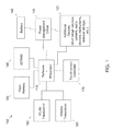
- FIG. 1 illustrates an example of information handling device circuitry.
- FIG. 2 illustrates another example of an information handling device.
- FIG. 3 illustrates an example view of a device including a contoured edge control.
- FIG. 4 illustrates another example view of a device including a contoured edge control.
- a contoured or shaped edge e.g., a cylindrical edge included with a tablet computing device
- An embodiment thus provides one or more input devices, e.g., a contoured button that is/are embedded into the shaped or contoured edge.
- a contoured button that is/are embedded into the shaped or contoured edge.
- This permits a user to simply provide a tap (e.g., using a thumb on the hand holding the device) to operate a function of the device, e.g., to take a picture using the camera.
- a tap e.g., using a thumb on the hand holding the device
- integration of the contoured control with the camera is just an example function for such a contoured input device.
- contoured input device e.g., a button or touch sensitive surface, optical input device, etc.
- a button or touch sensitive surface e.g., a button or touch sensitive surface, optical input device, etc.
- another contoured input device e.g., a button or touch sensitive surface, optical input device, etc.
- FIG. 1 includes a system on a chip or circuit design found for example in tablet or other mobile computing platforms.
- Software and processor(s) are combined in a single chip or circuit 110 .
- Processors comprise internal arithmetic units, registers, cache memory, busses, I/O ports, etc., as is well known in the art. Internal busses and the like depend on different vendors, but essentially all the peripheral devices ( 120 ) may attach to a single chip or circuit 110 .
- the circuitry 100 combines the processor, memory control, and I/O controller hub all into a single chip 110 . Also, systems 100 of this type do not typically use SATA or PCI or LPC. Common interfaces, for example, include SDIO and I2C.
- power management chip(s) or circuit(s) 130 e.g., a battery management unit, BMU, which manage power as supplied, for example, via a rechargeable battery 140 , which may be recharged by a connection to a power source (not shown).
- BMU battery management unit
- a single chip or circuit, such as 110 is used to supply BIOS like functionality and DRAM memory.
- System 100 typically includes one or more of a WWAN transceiver 150 and a WLAN transceiver 160 for connecting to various networks, such as telecommunications networks and wireless Internet devices, e.g., access points. Additional devices 120 may be included, for example a camera. Commonly, system 100 will include a touch screen 170 for data input and display/rendering. System 100 also typically includes various memory devices, for example flash memory 180 and SDRAM 190 .
- FIG. 2 depicts a block diagram of another example of information handling device circuits, circuitry or components.
- the example depicted in FIG. 2 may correspond to computing systems such as the THINKPAD series of personal computers sold by Lenovo (US) Inc. of Morrisville, N.C., or other devices.
- embodiments may include other features or only some of the features of the example illustrated in FIG. 2 .
- FIG. 2 includes a so-called chipset 210 (a group of integrated circuits, or chips, that work together, chipsets) with an architecture that may vary depending on manufacturer (for example, INTEL, AMD, ARM, etc.).
- INTEL is a registered trademark of Intel Corporation in the United States and other countries.
- AMD is a registered trademark of Advanced Micro Devices, Inc. in the United States and other countries.
- ARM is an unregistered trademark of ARM Holdings plc in the United States and other countries.
- the architecture of the chipset 210 includes a core and memory control group 220 and an I/O controller hub 250 that exchanges information (for example, data, signals, commands, etc.) via a direct management interface (DMI) 242 or a link controller 244 .
- DMI direct management interface
- the DMI 242 is a chip-to-chip interface (sometimes referred to as being a link between a “northbridge” and a “southbridge”).
- the core and memory control group 220 include one or more processors 222 (for example, single or multi-core) and a memory controller hub 226 that exchange information via a front side bus (FSB) 224 ; noting that components of the group 220 may be integrated in a chip that supplants the conventional “northbridge” style architecture.
- processors 222 comprise internal arithmetic units, registers, cache memory, busses, I/O ports, etc., as is well known in the art.
- the memory controller hub 226 interfaces with memory 240 (for example, to provide support for a type of RAM that may be referred to as “system memory” or “memory”).
- the memory controller hub 226 further includes a LVDS interface 232 for a display device 292 (for example, a CRT, a flat panel, touch screen, etc.).
- a block 238 includes some technologies that may be supported via the LVDS interface 232 (for example, serial digital video, HDMI/DVI, display port).
- the memory controller hub 226 also includes a PCI-express interface (PCI-E) 234 that may support discrete graphics 236 .
- PCI-E PCI-express interface
- the I/O hub controller 250 includes a SATA interface 251 (for example, for HDDs, SDDs, etc., 280 ), a PCI-E interface 252 (for example, for wireless connections 282 ), a USB interface 253 (for example, for devices 284 such as a digitizer, keyboard, mice, cameras, phones, microphones, storage, other connected devices, etc.), a network interface 254 (for example, LAN), a GPIO interface 255 , a LPC interface 270 (for ASICs 271 , a TPM 272 , a super I/O 273 , a firmware hub 274 , BIOS support 275 as well as various types of memory 276 such as ROM 277 , Flash 278 , and NVRAM 279 ), a power management interface 261 , a clock generator interface 262 , an audio interface 263 (for example, for speakers 294 ), a TCO interface 264 , a system management bus interface 265 , and
- the system upon power on, may be configured to execute boot code 290 for the BIOS 268 , as stored within the SPI Flash 266 , and thereafter processes data under the control of one or more operating systems and application software (for example, stored in system memory 240 ).
- An operating system may be stored in any of a variety of locations and accessed, for example, according to instructions of the BIOS 268 .
- a device may include fewer or more features than shown in the system of FIG. 2 .
- Information handling device circuitry may be used in devices that provide a contoured edge.
- FIG. 3 an example tablet computing device 300 is illustrated.
- the device 300 includes a main housing 301 that includes, e.g., a touch screen display 302 . As illustrated in the example of FIG. 3 , the device 300 may have a housing that is substantially quadrilateral (e.g., rectangular) but also includes a contoured or shaped edge 303 , here in the form of a substantially cylindrical shaped edge 303 .
- the device 300 may include, according to an embodiment, one or a plurality of contoured input devices, e.g., contoured input device 304 , incorporated into the contoured edge 303 .
- the example of FIG. 3 includes a contoured input device 304 , e.g., a ring shaped button or other device.
- the contoured input device 304 may accept touch based input and be formed to coordinate with the shape (here, a contoured edge 303 that is cylindrical in form) of the edge, which allows the contoured input device 304 to be embedded in the contoured edge 303 of such a device 300 .
- the button 304 surface is curved or takes on a ring shape in order to match the cylinder of the contoured edge 303 .
- This configuration allows the button 304 to be placed in the contoured edge 303 such that it does not disrupt the aesthetic quality of the contoured edge, does not interrupt the hinged nature of the contoured edge, and additionally allows the button 304 to be pressed from various angles of approach.
- the button 304 may be implemented in a variety of forms, e.g., as a mechanical or a capacitive touch switch.
- a mechanical form may rely on a central axis point which is moved whenever the button 304 is pressed from any angle to activate the switch.
- Other configuration may be acceptable or preferable, e.g., depending on the shape of the contoured edge 303 , the functionality associated with the contoured input device 304 , etc.
- a device 400 may include the contoured input device 404 in a location such that it is readily accessible during single handed use, as illustrated.
- a contoured input device 404 may be located proximate to one of the ends of the contoured edge 403 such that it is readily tapped, e.g., using a thumb.
- More than one contoured input device 404 may be included in the contoured edge, e.g., to accommodate left and right handed use.
- two contoured input devices 404 (only one being illustrated) may be included, such as incorporating a contoured input device 404 at opposite ends of the contoured edge 403 .
- an embodiment may alter the functionality of the contoured input device(s) 404 , e.g., based on a holding orientation (e.g., as sensed via positional sensors such as an accelerometer, gyroscope, and compass), a currently running or active application, etc.
- a contoured input device 404 may have its functionality changed, altered, removed, or adjusted depending on which hand is being used to hold the device, e.g., as determined via mapping sensed positional inputs to a predetermined pattern of device use (e.g., left handed, right handed) and/or via use selection.
- a particular application being used may change or adjust the functionality of the contoured input device 404 , e.g., to map input received via the contoured input device 404 to an underlying application control action, e.g., taking a picture with a camera application responsive to detecting input via the contoured input device 404 .
- one or more of the contoured input devices 404 may be deactivated or activated based on a variety of parameters, e.g., holding orientation, running application(s), or even the physical configuration of the device, e.g., position of a stand element 305 (referring back to FIG. 3 ) with respect to the housing 301 .
- an embodiment may alter or adjust the contoured input device 404 functionality based on a variety of parameters.
- aspects may be embodied as a system, method or device program product. Accordingly, aspects may take the form of an entirely hardware embodiment or an embodiment including software that may all generally be referred to herein as a “circuit,” “module” or “system.” Furthermore, aspects may take the form of a device program product embodied in one or more device readable medium(s) having device readable program code embodied therewith.
- a storage medium may be, for example, an electronic, magnetic, optical, electromagnetic, infrared, or semiconductor system, apparatus, or device, or any suitable combination of the foregoing. More specific examples of a storage medium would include the following: a portable computer diskette, a hard disk, a random access memory (RAM), a read-only memory (ROM), an erasable programmable read-only memory (EPROM or Flash memory), an optical fiber, a portable compact disc read-only memory (CD-ROM), an optical storage device, a magnetic storage device, or any suitable combination of the foregoing.
- a storage medium is not a signal and “non-transitory” includes all media except signal media.
- Program code embodied on a storage medium may be transmitted using any appropriate medium, including but not limited to wireless, wireline, optical fiber cable, RF, et cetera, or any suitable combination of the foregoing.
- Program code for carrying out operations may be written in any combination of one or more programming languages.
- the program code may execute entirely on a single device, partly on a single device, as a stand-alone software package, partly on single device and partly on another device, or entirely on the other device.
- the devices may be connected through any type of connection or network, including a local area network (LAN) or a wide area network (WAN), or the connection may be made through other devices (for example, through the Internet using an Internet Service Provider), through wireless connections, e.g., near-field communication, or through a hard wire connection, such as over a USB connection.
- LAN local area network
- WAN wide area network
- Internet Service Provider for example, AT&T, MCI, Sprint, EarthLink, MSN, GTE, etc.
- Example embodiments are described herein with reference to the figures, which illustrate example methods, devices and program products according to various example embodiments. It will be understood that the actions and functionality may be implemented at least in part by program instructions. These program instructions may be provided to a processor of a general purpose information handling device, a special purpose information handling device, or other programmable data processing device to produce a machine, such that the instructions, which execute via a processor of the device implement the functions/acts specified.
Abstract
Description
Claims (17)
Priority Applications (1)
| Application Number | Priority Date | Filing Date | Title |
|---|---|---|---|
| US14/178,430 US9354661B2 (en) | 2014-02-12 | 2014-02-12 | Contoured edge controls for hand held devices |
Applications Claiming Priority (1)
| Application Number | Priority Date | Filing Date | Title |
|---|---|---|---|
| US14/178,430 US9354661B2 (en) | 2014-02-12 | 2014-02-12 | Contoured edge controls for hand held devices |
Publications (2)
| Publication Number | Publication Date |
|---|---|
| US20150227169A1 US20150227169A1 (en) | 2015-08-13 |
| US9354661B2 true US9354661B2 (en) | 2016-05-31 |
Family
ID=53774887
Family Applications (1)
| Application Number | Title | Priority Date | Filing Date |
|---|---|---|---|
| US14/178,430 Active 2034-05-31 US9354661B2 (en) | 2014-02-12 | 2014-02-12 | Contoured edge controls for hand held devices |
Country Status (1)
| Country | Link |
|---|---|
| US (1) | US9354661B2 (en) |
Citations (9)
| Publication number | Priority date | Publication date | Assignee | Title |
|---|---|---|---|---|
| US7206198B2 (en) * | 2004-08-11 | 2007-04-17 | Hon Hai Precision Industry Co., Ltd. | Portable computer with handle-cum-stand |
| US20080068786A1 (en) * | 2006-09-20 | 2008-03-20 | Arima Computer Corporation | Tablet pc and method for sustaining the same |
| US20090237878A1 (en) * | 2008-03-19 | 2009-09-24 | Micro-Star Int'l Co., Ltd. | Electronic device structure |
| US20090303676A1 (en) * | 2008-04-01 | 2009-12-10 | Yves Behar | System and method for streamlining user interaction with electronic content |
| US8289688B2 (en) * | 2008-04-01 | 2012-10-16 | Litl, Llc | Portable computer with multiple display configurations |
| US8295039B2 (en) * | 2009-11-24 | 2012-10-23 | Hon Hai Precision Industry Co., Ltd. | Electronic device |
| US8405978B2 (en) * | 2011-02-24 | 2013-03-26 | Kabushiki Kaisha Toshiba | Electronic device |
| US8824134B2 (en) * | 2010-10-28 | 2014-09-02 | Asustek Computer Inc. | Tablet electronic device |
| US20140362512A1 (en) * | 2013-06-06 | 2014-12-11 | Matthew C. Hinson | Electronic retractable blueprint display device for viewing and manipulating full-size and half-size architectural, engineering, and construction plans |
-
2014
- 2014-02-12 US US14/178,430 patent/US9354661B2/en active Active
Patent Citations (10)
| Publication number | Priority date | Publication date | Assignee | Title |
|---|---|---|---|---|
| US7206198B2 (en) * | 2004-08-11 | 2007-04-17 | Hon Hai Precision Industry Co., Ltd. | Portable computer with handle-cum-stand |
| US20080068786A1 (en) * | 2006-09-20 | 2008-03-20 | Arima Computer Corporation | Tablet pc and method for sustaining the same |
| US7502222B2 (en) * | 2006-09-20 | 2009-03-10 | Arima Computer Corporation | Tablet PC and method for sustaining the same |
| US20090237878A1 (en) * | 2008-03-19 | 2009-09-24 | Micro-Star Int'l Co., Ltd. | Electronic device structure |
| US20090303676A1 (en) * | 2008-04-01 | 2009-12-10 | Yves Behar | System and method for streamlining user interaction with electronic content |
| US8289688B2 (en) * | 2008-04-01 | 2012-10-16 | Litl, Llc | Portable computer with multiple display configurations |
| US8295039B2 (en) * | 2009-11-24 | 2012-10-23 | Hon Hai Precision Industry Co., Ltd. | Electronic device |
| US8824134B2 (en) * | 2010-10-28 | 2014-09-02 | Asustek Computer Inc. | Tablet electronic device |
| US8405978B2 (en) * | 2011-02-24 | 2013-03-26 | Kabushiki Kaisha Toshiba | Electronic device |
| US20140362512A1 (en) * | 2013-06-06 | 2014-12-11 | Matthew C. Hinson | Electronic retractable blueprint display device for viewing and manipulating full-size and half-size architectural, engineering, and construction plans |
Also Published As
| Publication number | Publication date |
|---|---|
| US20150227169A1 (en) | 2015-08-13 |
Similar Documents
| Publication | Publication Date | Title |
|---|---|---|
| US11036260B2 (en) | Keyboard attachment to foldable device | |
| US10416856B2 (en) | Handedness for hand-held devices | |
| US11334113B2 (en) | Disabling touch input to information handling device | |
| US9557911B2 (en) | Touch sensitive control | |
| US9939874B2 (en) | Selectively disabling sensors and associated functions | |
| US20150363008A1 (en) | Displaying a user input modality | |
| US10345927B2 (en) | Pen/stylus offset modification | |
| US10963159B2 (en) | Virtual interface offset | |
| US9134835B2 (en) | Detecting and filtering edge touch inputs | |
| US20170325038A1 (en) | Audio device arrays in convertible electronic devices | |
| US20150205360A1 (en) | Table top gestures for mimicking mouse control | |
| US11614504B2 (en) | Command provision via magnetic field variation | |
| US9354661B2 (en) | Contoured edge controls for hand held devices | |
| US11237641B2 (en) | Palm based object position adjustment | |
| US20170168597A1 (en) | Pen hover range | |
| US9740923B2 (en) | Image gestures for edge input | |
| US10764511B1 (en) | Image version selection based on device orientation | |
| US10579319B2 (en) | Activating a device system without opening a device cover | |
| US20150362990A1 (en) | Displaying a user input modality | |
| US11836418B2 (en) | Acknowledgement notification based on orientation state of a device | |
| US8880754B1 (en) | Rotational input area for information handling device | |
| US11928264B2 (en) | Fixed user interface navigation | |
| US9271108B2 (en) | Secure tap to transfer objects | |
| US11017746B2 (en) | Auxiliary display scaling factor | |
| US20220171530A1 (en) | Displaying a user input modality |
Legal Events
| Date | Code | Title | Description |
|---|---|---|---|
| AS | Assignment |
Owner name: LENOVO (SINGAPORE) PTE. LTD., SINGAPORE Free format text: ASSIGNMENT OF ASSIGNORS INTEREST;ASSIGNOR:PARKER, JOSEPH ROBERT;REEL/FRAME:032201/0026 Effective date: 20140207 |
|
| STCF | Information on status: patent grant |
Free format text: PATENTED CASE |
|
| AS | Assignment |
Owner name: LENOVO PC INTERNATIONAL LIMITED, HONG KONG Free format text: ASSIGNMENT OF ASSIGNORS INTEREST;ASSIGNOR:LENOVO (SINGAPORE) PTE. LTD.;REEL/FRAME:049688/0741 Effective date: 20160701 |
|
| MAFP | Maintenance fee payment |
Free format text: PAYMENT OF MAINTENANCE FEE, 4TH YEAR, LARGE ENTITY (ORIGINAL EVENT CODE: M1551); ENTITY STATUS OF PATENT OWNER: LARGE ENTITY Year of fee payment: 4 |
|
| MAFP | Maintenance fee payment |
Free format text: PAYMENT OF MAINTENANCE FEE, 8TH YEAR, LARGE ENTITY (ORIGINAL EVENT CODE: M1552); ENTITY STATUS OF PATENT OWNER: LARGE ENTITY Year of fee payment: 8 |