US933374A - Envelop-machine. - Google Patents
Envelop-machine. Download PDFInfo
- Publication number
- US933374A US933374A US1907358202A US933374A US 933374 A US933374 A US 933374A US 1907358202 A US1907358202 A US 1907358202A US 933374 A US933374 A US 933374A
- Authority
- US
- United States
- Prior art keywords
- paper
- shaft
- trimmer
- roller
- roll
- Prior art date
- Legal status (The legal status is an assumption and is not a legal conclusion. Google has not performed a legal analysis and makes no representation as to the accuracy of the status listed.)
- Expired - Lifetime
Links
Images
Classifications
-
- B—PERFORMING OPERATIONS; TRANSPORTING
- B31—MAKING ARTICLES OF PAPER, CARDBOARD OR MATERIAL WORKED IN A MANNER ANALOGOUS TO PAPER; WORKING PAPER, CARDBOARD OR MATERIAL WORKED IN A MANNER ANALOGOUS TO PAPER
- B31B—MAKING CONTAINERS OF PAPER, CARDBOARD OR MATERIAL WORKED IN A MANNER ANALOGOUS TO PAPER
- B31B50/00—Making rigid or semi-rigid containers, e.g. boxes or cartons
- B31B50/14—Cutting, e.g. perforating, punching, slitting or trimming
- B31B50/16—Cutting webs
-
- Y—GENERAL TAGGING OF NEW TECHNOLOGICAL DEVELOPMENTS; GENERAL TAGGING OF CROSS-SECTIONAL TECHNOLOGIES SPANNING OVER SEVERAL SECTIONS OF THE IPC; TECHNICAL SUBJECTS COVERED BY FORMER USPC CROSS-REFERENCE ART COLLECTIONS [XRACs] AND DIGESTS
- Y10—TECHNICAL SUBJECTS COVERED BY FORMER USPC
- Y10T—TECHNICAL SUBJECTS COVERED BY FORMER US CLASSIFICATION
- Y10T83/00—Cutting
- Y10T83/202—With product handling means
- Y10T83/2066—By fluid current
- Y10T83/207—By suction means
-
- Y—GENERAL TAGGING OF NEW TECHNOLOGICAL DEVELOPMENTS; GENERAL TAGGING OF CROSS-SECTIONAL TECHNOLOGIES SPANNING OVER SEVERAL SECTIONS OF THE IPC; TECHNICAL SUBJECTS COVERED BY FORMER USPC CROSS-REFERENCE ART COLLECTIONS [XRACs] AND DIGESTS
- Y10—TECHNICAL SUBJECTS COVERED BY FORMER USPC
- Y10T—TECHNICAL SUBJECTS COVERED BY FORMER US CLASSIFICATION
- Y10T83/00—Cutting
- Y10T83/202—With product handling means
- Y10T83/2092—Means to move, guide, or permit free fall or flight of product
- Y10T83/2183—Product mover including gripper means
-
- Y—GENERAL TAGGING OF NEW TECHNOLOGICAL DEVELOPMENTS; GENERAL TAGGING OF CROSS-SECTIONAL TECHNOLOGIES SPANNING OVER SEVERAL SECTIONS OF THE IPC; TECHNICAL SUBJECTS COVERED BY FORMER USPC CROSS-REFERENCE ART COLLECTIONS [XRACs] AND DIGESTS
- Y10—TECHNICAL SUBJECTS COVERED BY FORMER USPC
- Y10T—TECHNICAL SUBJECTS COVERED BY FORMER US CLASSIFICATION
- Y10T83/00—Cutting
- Y10T83/202—With product handling means
- Y10T83/2092—Means to move, guide, or permit free fall or flight of product
- Y10T83/2183—Product mover including gripper means
- Y10T83/219—Rotating or oscillating product handler
-
- Y—GENERAL TAGGING OF NEW TECHNOLOGICAL DEVELOPMENTS; GENERAL TAGGING OF CROSS-SECTIONAL TECHNOLOGIES SPANNING OVER SEVERAL SECTIONS OF THE IPC; TECHNICAL SUBJECTS COVERED BY FORMER USPC CROSS-REFERENCE ART COLLECTIONS [XRACs] AND DIGESTS
- Y10—TECHNICAL SUBJECTS COVERED BY FORMER USPC
- Y10T—TECHNICAL SUBJECTS COVERED BY FORMER US CLASSIFICATION
- Y10T83/00—Cutting
- Y10T83/444—Tool engages work during dwell of intermittent workfeed
- Y10T83/461—With abutment to position work being fed with respect to cutter
Definitions
- Fig. 17 is u bottom plan View of thc guide "f' The perticulnr features of novelty inthe in the present cese an entire envelop'mnchine.
- FIG 8 showing the mechanism iii-advanced essere.
- M vginventioii comprises certain features ot novelty which Will be described in the which the following a specification.
- Lilcevrccrcnce ninnernlsare employed to designate like parts in all the figures.
- Fig. 11 is :i plan view oFigQ.
- Fig. 12 is .a detail sectionahview of thel auxiliary feed roller.
- Fig. 13 isfn side ele-*- vation of the gearing of the rotary-trimmer and paste applying roller.
- Fig.v 141s 'a plan view ofthe guide plate lleading to'the rotary?l trimmer.
- Fig. 15 is ai sect-ionl'ielevetinvoff the stime. on line D-D, Fig. 14.
- Fig. 16 is e central sectional elevation of the same.
- Fig. 18 is n plan View of the lower portion ofthe mec-lime, certain parts being to the flap.
- Fig. 20 is e view of themeensfor supporting ⁇ and guidi the paste .mechnmsm'.
- Fig. 23 is an end View of the same.
- Fig. 26 is adetail of e Iportion of the main frameshowing a.sup ⁇
- FIG.v2l is a. detai view of 'partof Fig. 22 is n side elevation of the Figs. 24 ⁇ and 25 are detail4 views of the supporting trunnionso seid port ⁇ for the supporting mechanism.
- Fig. 28 is a bottom' view of the same.
- ⁇ 29 is a1 section on the line E--E, Fig.,2
- F ig. 30 is a detail viewshbwing the means for driving the folding rollers.
- Fig. 8l is a longitudinal vertical section of the scoring rollers of the folding mechanism.
- Fi 32 und 33 are detail views of the lap fo ding plate.
- F ig. 34 is a'detail 4View, in section,
- Figs. 35, 36 'and 37 are views showing the various stages of (the envelop blank.
- 1 and 2 designate the front and rear legs of the Inachine. Supported upon seid legs ure the stitute the main frame of the machine, and upon them' the various mechanisms are Ymounted. ⁇ iHung in a 4pair of depending hooks 5 et the forward end of the frame, is the roll axle 6 having a roll of peper 7, which is .to 10Q' be made into envelope',
- a rod 8 Whose thread- 3 has rotatably mounted thereon a frame9 #which is prevented ⁇ from sliding on the shaft held against the paper roll by the pressure 110 beams 3 and 4.
- These beams 3 and 4 con ⁇ ed end Works in a. threaded hole inthe beam iosa of the spring 13.
- the stationary guiding disk 11 may be brought up against the side of the paper roll by turning the rod 8 by its handle 14.'
- the gear wheel 19 is in mesh with a large idle gear Wheel 26 keyed on a shaft 27 and the gear wheel 26 in turn meshes with a gear wheel 28.
- the gear wheel 28 is keyed on a shaft 29.
- the shaft 29 carries a cylinder 30, which I shall call the cutter cylinder and which will be described in det-ail hereinafter.
- the gear wheel 28 meshes with a gear wheel 31 which is keyed on a shaft 32 and has the same number of teeth as the gear wheel 28.
- lSaid shaft 32 carries a roller 33 which serves the purpose of a platen in the printing operation, and hence I call it the platen.
- a air of hangers 34 (see Fig. 3) support an id e roller 35, and the paper web coming off the roll 7 passes over the idle roller 35, under the platen 33 (Where the printing takes place) and over the cutter cylinder 30, as will be more fully described hereinafter.
- the paste applying mechanism receives its operating power throu h the gear wheel 22 which is keyed on the ottom roll shaft 20. Said gear wheel 22 meshes with a g'ear wheel 40 keyed to a shaft. 41 which carries the mechanism for applying the paste.
- My improved envelop machine is also provided with a printing mechanism, which may best be seen in Figs. 1, 2 and 3.
- This printer is operated in the following manner:
- the platen shaft 32 has keyed thereon a gear wheel 42 (Fig. 2) which meshes with a ⁇ gear wheel 43 on the printing cylinder shaft 44.
- Said shaft44 carries they printing cylinder 45 (see Figs. 1 and 2).
- Said -gear wheel 43 in turn meshes with a gear wheel 4G (see Fig. 2) which is keyed on the shaft 47 (sec Fig. 3) carrying the inking roller (not shown).
- the printer will be described in detail hereinafter.
- the printer shaft 44 has keyed to it a gear wheel 48 which drives a gear wheel 49 keyed to a shaft 50, (see Figs. 2, 3 and 27,).
- the shaft 50 also has a gear wheel 51 keycd thereon, said gear wheel 51 meshing with a series of idlers and gear wheels to operate the separate parts of the folding mechanism, all of which will be clearly described in detail later on.
- Figs. 1 and 3 For the purpose of pressing down the laps and delivering ⁇ thevenvelops, I use the well known device shown clearly in Figs. 1 and 3, which, for convenience, I designate the seam presser.
- This mechanism is driven in the following manner.
- the shaft 27 (see Fig. 1) has keyed to it a small pinion 52 which meshes with a transmission gear 53 on a stud 54 secured to the frame of the inachine.
- 'Said stud 54 has keyed thereon a pinion 55 which meshes with a large transmission gear wheel 56 mounted on a stud 57 on the main frame of Ithe machine.
- Said stud 57 also carries a fixed pulley 58 over which a belt 59 travels and conveys power to a pulley wheel 60 fixed on the seam presser shaft 61.
- the first operation to which the paper is subjected is the printing.
- the printing mechanism may be of any Well known type. I have shown in Fig. 3 a very simple form.
- An ink-fountain 64 supplied with ink has a feed roller (i5 rotatingl therein and a roller G6 operated by a cam (not shown) is intermittently moved into engagement Iwith said roller 65.
- the :said dsp'illating roller (56 transfers the ink to a roller 67 which is always in engagement with the main inking roller 48.
- the distributing rollers 68 and (39 distribute the ink evenly over the main roller 48 and the rollers 70 and 71 transfer the ink from roller 48 to the printer cylinder 45.
- the printing is done by the printer cylinder 45 acting against the paper as it passes under the platen 33.
- the next operation is the lap cutting. 'The mechanism for this is shown in Figs. 3, 4, 5, and 7.
- the shaft 29 carries a cutting cylinder 30.
- This cylinder as clearly shown in Figs. 4' and 5 is not regular, but has :1 body portion 72 and a cutter portion 73. Said cutter portion 73 has edges adapted to cut the paper along the line A of Fig. 35
- I provide the mechanism with a pairioi1 ⁇ pressure rollers 7st and 75.
- Said pressure rollers 7a and 75 are pivoted by f', pivot pins 7G and 77 in sockets 78 and 79,
- Another feature of novelty in thiscutting mechanism is a device for ⁇ breaking away the Waste which has been cut on'. It is found in prac tice that' the cut made by the mechanism just described isnot clean at the end and the waste has a tendency to hold on to the web.
- l provide each'side of the body portion 72 ofthe cyll. inder 30 With a stud 94 and pivot thereon a rocking lever 95- as clearly shown in Figs. 6 and 7.
- Said' rocking lever 95 has at one end a flange orA bent portion 96 and at thev other a lug 97.
- Said lug 97 has ei'igaging it a leaf spring 98 which is so mounted in the cylinder 30 that the flange end .96 of the 'rocking lever 95 is held,normally down.
- vtriminii'i 101 is'rotated by a belt. 103 ⁇ diivenby a puli ley 104 on the bottoni roll shaft 20.
- The) roller 102 being in contact with the roller 101 will rotate with the saine and the waste strip will, Athus be gripped by the pair and carried nrito/'a suction shaft 105 or' any Well known .'piistruction.
- the paper web After the paper web has left tne lap cutting mechanism, it passes down under the idle roller (SZ, up between the bottom roll 21 and the idler 63, and between the bottom roll 21 and the forni roll 25. This portion ot' the machine is best illustrated in Figs. 2, 3, 8 to 12, and 18.
- baid guide 'plate 108 is' screwed to the beam 199 by the screws 110.
- the stationary knife blade 111 is secured oi'iithe top ot' the beam 109.
- a stop plate 112 provided Withan elongate finger 113, and having-its" body portion slotted to receive a set screw y114C is superposed on said stationary knife blade and the set screw 1141 is fastened therein so as to hold the stop plate 1.12 in proper position. 'lhe position of said stop plate may obviously be varied clearly in Fig.
- the bottom roll 21 has gripped i the paper unit in the place which 1s to be the end of the envelop opposite to the Hap, and 'starts to fold. the paper onv itself and carry it downward toward the paste roller.
- the tirst7 ⁇ jlfipj'iine' mechanism is at the top of the bottom roll 21 and is represented as beingr just about to ⁇ o'rip the paper.
- he bottoni roll 21 as shown in the drawing' is provided with a longitudinal perforation which is circular in cross section and a longitudinal slot communicates therewith from the surface of the roll.
- .YX rod-11T provided with a single eloi'ip'ated gripping blade 118 tits in the recess thus formed. the gripping blade 118 occupying' the' slot but. capable of oscillating ⁇ therein as the rod 11T rocks in its bed.
- Said rod 11T has. keyed to one ot' its ends just outside the cylinder.
- a rollar 1 t9 which is provided with a spring' aiachment hre' 120.
- spring attaching: hre' 121 (not shown in Fig'. S) is provided on thel bottom roll and between these two lugs a spring;A 122 is strung the tension ot which tends to rock .the rodi117 and ,thus cause.
- the lever 124 is operated by running into the cam Y surface 127 on said cam cylinder, and rises a gainst the tension of the gripper spring', unt1l itis travehng'over theregular suri'acc ot the cam cylinder 125.
- a spring ⁇ 12S may be attached to the collar 123 and the bottom roll in a similar manner to that already described,
- the second gripper comprises a rod 129, a pgripj'iing' blade 1230, a millar 131 at one end ofsaid rod 129, spring ⁇ attaching' lugs 132 and 133 and a. spring' 13st; a collar 1235 at the.
- ri ⁇ he scoring mechanism ot' the form roll,- which, as mentioned above, serves the purposobf pushing a bight of the paper into the grippers.
- lriaid scoring' mechanism comprises a scoring ba r 139 which is'set in a slot 140 in the forni roll, said scoring bar projecting a little way beyond the periphery or' the form roll.
- the scoring bar 139 has also reduced ends 141 which extend beyond the ends of the roll and over which detaining,l lugs 142 are placed to prevent the scoring bar from 'falling out,
- '.l ⁇ hese detaining lugs 112 may be screwed to theI end oit the roll as shown in Figs. 9 and 10.
- a spring. ⁇ 113 fitting.v in a recess 111 in each end of the' torni roll is suitably attached to each end ot" the scoring bar and havingr its other end secured to the wall of the recess 111 serves to normally hold the scoring bar against the forward wall of the slot 1-1-0. p
- the journal blocks 145 may move up or down in their tracks or ways 1116, against the tension of the springs 117 which may be adjusted by bJlts 11S passing; through cross bars 1119 at the top of said ways. This allows of self adjustment for different thicknesses of paper which may pass between the bottom ro and the form roll.
- the rotation of the torni roll and the bottom roll is so regulated by their gears that the scoringr bar will descend into the gripper slot right against the side o1 the gripper blade, and at thaty moment the cani lets no of the lever and allows the gripper springs to rock the gripper against, the tension of the scoring bar springs until the scoring' bar has been withdrawn from the gripper slot and it then ⁇ grips the bight of paper which was forced into it by the scoring' bar and carries it down in its rotation.
- a plate 191 extends across the machine at the underneath side of the machine frame, and to this are secured the jaws 192, 193, 19%1 and 195 of the side frames 196 and 197 of the folding mechanism.
- the plate 191 is provided with slots 198 and 199 throughlwhich pass bolts 200 and 201 for laterally adjusting the position of the folding mechanism on the plate.
- This frame serves as the support for two belt movements, which, for convenience of de scription, 1 shall designate as the upper belt and the lower belt movements.
- the envelop is carried between the upper and lower belts. Each belt movement carries a pair of belts.
- the shaft 50 carries a gear wheel 51, which, as stated before and shown in ⁇ Fig. 27, is driven by the gear wheel 19.
- the gear wheel 51 drivesan idler 202 which is in mesh with a secondidler 203, said idler 203 driving the gear wheel 2011 keyed on the shaft 205.
- the shaft 50 drives the upper belts, and the shaft '205 drives the lower belts.
- the shaft 50 carries a. belt pulley 206 over which the upper belt 207 travels, 'the other end of said belt 207 being carried by the pulley 208 which may be either integral with or keyed to a shaft 209.
- the shaft 209 is journaled at this end in the side frame 197, and a retaining collar 210 is keyed on the reduced end of the shaft outside of the frame.
- the shaft 205 drives vthe lower belt. This is done by a belt pulley 211 on said shaft 205, the belt 212 passing around said pulleyr and h ving its other en supported by the pulley 13 either integral with or keyed to a shaft 214.
- the reducedv end of said shaft 211 ⁇ isj onrnaled in the side frame 197 and keyedrthereon is a retaining ring-213.
- an idle roller 216 bearing on said belt is mounted lon a shaft 217 which may be bolted in proper position in the slotted arm 218 of the side frame 197.
- a similar device is provided for adjusting the tension of the lower belt212, which comprises a roller 219.1nounted on'a shaft 220 which is bolted in proper position in a slotted arm 221 of the side frame 197.
- the upper belt serves as the pressure belt, while the lower belt serves. as the carrying belt.
- rollers 222 and 223 are also provided with central longitudinal cavities or recesses 228 and 229 into which slide the shafts 230 and 231.
- I also provide a scoring mechanism in the folding mechanism.
- I provide a pair of scoring rollers 232 and 233. (See Fig. 31.)
- the upper roller 232 is integral with a shaft 2311, the reduced end 235 of which is journaled in slot 236 of the side frame 197 and has a retaining ring 237 keyed to its end.
- a spring pressure bearing,r 238 tends to keep the upper scoring roller against the lower scoring roller (seo F ig. 30).
- the lower scoring roller 233 is integral with a shaft 239 which has its reduced end 240, journaled in the side frame and provided With a retaining ring 241 keyed thereto.
- the scoring roller 233 assists in.carry ing the belt 212.
- the belt pulley 245 drives the upper belt 246, and the other end of said. belt travels over an idle pulley 2Jf7 whiehs integral with a sleeve 218 splined on the yshaft 209 and journaled in the side frame 196, a retainingring 219 being keyed on the end of the sleeve.
- the sleeve 248 has also a shoulder 25() abutting against the side frame 196.
- the gear 'wheel' 20eL A is keyed to the end of a Sleeve .251, (Fig. 28) splined on the shaft 205i and journaled in the side macne 19o.
- the sleeve '251 has alo a belt pulley 253 yintegral therewith and airying a. lo-,Wer belt Q54.
- the lower belt- 254- is supported at its other ot' said 'sleeve 25o.
- an idle belt pulley 255 which is iiitegral with a Sleeve 256 eplined to the shaft 214A and ournaled in the side traine 19d.
- a retaining sleeve beingixkeyed to the end
- the .feeve 25o has also a Shoulder 258 abutting; against the side vfraine 19o.
- the tension of the upper belt 2l() being' adjusted by a pulley '59 mounted to rotate on a shaft 26th said shaft 2li() being); bolted in a lott 4l aini 261 of the side frainefitt.
- Hee lii The tension ofthe loiver beit E "l is adjusted by ineans of a' roller Q62 tlf.' 2li) which is iuoiinted to rotate on a shaft L63 bolted in a slotted ariu QG-'lof the inain fi-aine 196.
- The, upper belt Q-itl is borne upon by a pair of pressure rollers 265 and 2Go which are keyed to the above iiieni'ioned shafts 23) and 231, the endel of said ahafls resting' in slotsin the side fraine 196 and proiided with the retaining: ⁇ rings 26T and 26H.
- the .scoring nierhanisin at this side of the pen comprises a lower scoringI roller oil integral with a sleeve 2() Splined on the abore-intentioned shaft 239 and jour-
- the sleeve 2T() has at its end a retaining ⁇ ring' l ilfand is also provided 1with a Shoulder 272 abuttingl against they side fraine 196.
- the roller (39 assists in carrying; the lower belt 2li.
- the upper scoring roller Q73 is rotatably inounted ⁇ upon a shaft 234-. and its position i thereon is controlled bv tlie,scorin i' flange riiigyis shown at i fio of the bottoni .eeorino roller 269 which ivill roller '.l is held in suitable engagement' "with the lower scoring roller 26%).
- the shaft 205 has keyed to its end a pulley 275 which drives a belt 27h, the other end of Said belt'beinlticarried by a pulley 277 keyed to a shaft 278 which iournaled in' the inain frame of the machine and which carries a pairof presan'e rolls 279 and which are keyed thereto al fany desired position on the shaft.
- a stationary shaft 2531 on which are mounted the idlers and These idlers bear upon the rollers Q79 and 280 and are held in place by the sleeves Q81, 285, 286 and287.
- As-tlie envelop emerges from the end of the portion 290 of the folding plate it is delivered to the pressin r rollers cai-Tied b v the. shafts 278 'and-QSL already nientioiied, and by these rollers the 'lape are tightly pressed down.
- y Y l Froni the pressure rollers the envelop pase ⁇ oii tothe Seani presser mounted noon the shaft 61 and ehoivn in Figs. l and il of the drawings.
- This mechanism comprises a wheel 295 which is mounted in ⁇ afraine 290, saidjfraine having radial arnis at the endsof which are mounted ,a nuinber of idle pulleys'i 99'?
- This belt is driven by its frictional ron-tact with the circumference of the senin presser wheel 295, and the. envelope pass troni the pressi-ng roll-ers mentioned above they are received b v the vseein; presser and carried idovvn bet-Ween the belt and the eiicinnferences of the wheel, which further presses its the en- I ioo their laps and finally delivers theni to the de- ⁇ liveryboard 299.
- the combination With means for cutting a V-shaped slit in the paper; of a trimmer adapted to trim oit the ends of said V-shaped slit, a. guide receiving the paper from said cutting means anddirccting it to said trimmer, and means in thepath of the paper to the trimmer en gaging thelend of the paper and arresting it in proper position to be cutby said trimmer.
- arrestingit in proper posi-y guide receiving the paper from said cutting means and directing it to said ⁇ rotary trunmer, and means in the path ot the paper to the trimmer engaging in the apex of the,
- G. In an envelop machine, the combination with means for cutting a V-shaped slit in the paper; of a. trimmer adapted to trim oit' the ends of said V-shaped slit, a guide receiving the paper from said cutting means and directing it to said trimmer, and means in the path of the paper to the trimmer engaging in the apex of the V-sha )ed slit ⁇ ot the paper and arresting it and iolding lit down on the guide in proper position to be cut by said trimmer.
- the combination with means i'or cutting a V-shaped slit in the paper ot a rotary trimmer adapted to trim off the ends of said V-shaped slit, a guide receiving the paper from said cutting meansA and directing it to said rotary trimmer, and meansy in the path of the paper to the trimmer engaging in the apex-ot the V-shaped slit of the paper and arresting it and holding it down on the guide in proper position to be cut by said trimmer.
Landscapes
- Folding Of Thin Sheet-Like Materials, Special Discharging Devices, And Others (AREA)
Description
T. W. KIENAST.
l ENVELOP MACHINE.
APPLICATION FILED IBB. 19, 1907.
Pateuted Sept. 7, 1909.
12 SHBETS-SHEET 1.
.W7/'t1 @asses T. W. KIBNASZI?.4 BNVELOP MAGHINE.
I APPLIGATIN FILED FEB. 19, 1967. I 33,374, v l Patented Sept. '7,' 1909.
IZSHEETS-SIHEET 3. l
T. W. KIENAST.
ENVELOP MACHINE. APPLIGATION FILED EEB. 1Q, 190:'.
33.3%9 Patented Sgm. 7, 1909.
A 12 SHEETS-SHEET 5,
gg 125 y W. KIBNAST.
ENVELOP MACHINE.
APPLIOATION vULEB PEB. 19, 1907,
Patented Sept.' 7; 1909.
12 SHEETS-SHEET 8.
@wv/m T. W. KLENAST. ENVELOP MACHINE. APPLloATIoN FILED P11319, 1907,
Patented sept. fa-1.909.
l2 SHEETS-SHEET 7.
T. W. KIENAST.
ENVELOP MACHINE. APPLIOATION FILED 1113.19, 1907.
Wzese s:
T. W. KI'ENAST.
ENVBLOP MACHINE.
APPLICATION FILEnFnB. 19, 19o7.
Patented Sept. '7, 1909.
12 SHEETS-SHEET 10.
WFL-Messes ENVELOP MACHINE.
APPLIOATION FILED 113.19, 1907.
l2 SHEETS-SHEET 1l.
Patented Sept. 7, 1909.
@XS www T. W. KIENAST. BNVBLOP MACHINE.
APPLIOATION FILED FEB. 19, 1907.
Patented Sept. 7, 1909.
' 12 SBBTSHBET 12.
Wz'zesses: l v i n giu/egim?.
' l /16/ J.; .bmw-.iv
' Fig. 17 is u bottom plan View of thc guide "f' The perticulnr features of novelty inthe in the present cese an entire envelop'mnchine.
the mechanism of the bottom roller.' Fig. 9
.Fig 8, showing the mechanism iii-advanced essere.
@.witnrinunsnnsr, or Newsome, n. Y., essienon 'ro sen:
COMPANY, ornent Yonex, n. Y..
ein. f
Al CORPQRATQON F MISSOURI.
' Specification of Letters Patent.
Application ined February 1e, 19m'. semi no. 358,202.
fo all whom it may concern:
`l removed and partly disclosing the adjust.
Be it known that. I, l`.WILLiAM KIENAST, l able paste applying` mechanism. Fig. 19. is a. citizen of the'llnited States, and resident l a detail ot the means for applying the poste ot the borough ot' lvlzinhatten,` inthe cit.l
and State ot Kew York, have invented a cerj tain new and useful Envelop-Machine, of s' Figa 19.
M vginventioii comprises certain features ot novelty which Will be described in the which the following a specification.
specitication'end morefully pointed out in the claims.
{it-order tliat my invention muy be clearly understood by vthose skilled in the art, I have hereunto annexed-sheets of drawings illustrating my improved machine, and will presently describe the invention with reference to thc seme; y
Lilcevrccrcnce ninnernlsare employed to designate like parts in all the figures.
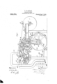
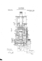
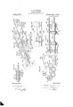
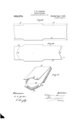
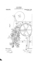
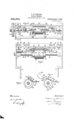
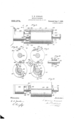
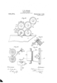
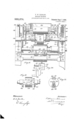
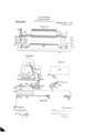
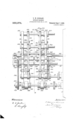
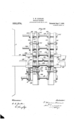
cutting' mechanism,` the envelop folding mechanism and the gumming mechanism are claimed specifically in divisional applica-v tions, but-in order to showan embodiment ofi my invention in a complete machine, I have shownin the drawings and described lnsaid drawings,"l `igure 1 is a side elevation oi the complete machine. Fig. 2 is a `plan View of the same. Fig. 3 is wvertical section on the line A-A, Fig. 2. Fig. Il is a plan view of the blank-cutting mechanism.` Fig.' 5 :i side elevation of the same. Fig. is u detail" View showing the mechanism for is a similm view showing the same mechanism inv an ndvanccdposition.' `Eig. `8 is a detail View showing the camsfor controlling is ev section on the line BeB, Fig. 8 showing themechanism for forming theblanlr, and Fig. l0 is a similar view on the line G-,C ofV position. Fig. 11 is :i plan view oFigQ.
Fig. 12 is .a detail sectionahview of thel auxiliary feed roller. Fig. 13 isfn side ele-*- vation of the gearing of the rotary-trimmer and paste applying roller. Fig.v 141s 'a plan view ofthe guide plate lleading to'the rotary?l trimmer. Fig. 15 is ai sect-ionl'ielevetinvoff the stime. on line D-D, Fig. 14. Fig. 16 is e central sectional elevation of the same.
finger. Fig. 18 is n plan View of the lower portion ofthe mec-lime, certain parts being to the flap. Fig. 20 is e view of themeensfor supporting` and guidi the paste .mechnmsm'.
pasting mechanism. Fig. 23 is an end View of the same.
`pasting mechanism. Fig. 26 is adetail of e Iportion of the main frameshowing a.sup`
UEL -cUrPLn's Eliminare `Fig.v2l is a. detai view of 'partof Fig. 22 is n side elevation of the Figs. 24`and 25 are detail4 views of the supporting trunnionso seid port` for the supporting mechanism. Figin n plan view of the folding mechanism'. Fig. 28 is a bottom' view of the same. Fi
`29 is a1 section on the line E--E, Fig.,2
F ig. 30 is a detail viewshbwing the means for driving the folding rollers. Fig. 8l is a longitudinal vertical section of the scoring rollers of the folding mechanism. Fi 32 und 33 are detail views of the lap fo ding plate. F ig. 34 is a'detail 4View, in section,
disclosin` the means for adjusting the fold.` i ing mec anism. Figs. 35, 36 'and 37 are views showing the various stages of (the envelop blank.
ln describing the mnehine,.1 shellfirst' trace out rather generally the. variousm'eehanisms of the machinewith, the connections lby which they are operated from the main driving'shnft, and then when I have givenv n general idea of the machine. and the releytion or each part. to the other, I shalltake up the individual mechanisms and describe the same in detail.
Referring now to said drawings, 1 and 2 designate the front and rear legs of the Inachine. Supported upon seid legs ure the stitute the main frame of the machine, and upon them' the various mechanisms are Ymounted. `iHung in a 4pair of depending hooks 5 et the forward end of the frame, is the roll axle 6 having a roll of peper 7, which is .to 10Q' be made into envelope', For the purpose of giiidingthe paper web, a rod 8 Whose thread- 3 has rotatably mounted thereon a frame9 #which is prevented `from sliding on the shaft held against the paper roll by the pressure 110 beams 3 and 4. These beams 3 and 4 con `ed end Works in a. threaded hole inthe beam iosa of the spring 13. The stationary guiding disk 11 may be brought up against the side of the paper roll by turning the rod 8 by its handle 14.'
with a gear Wheel 23 having the samenumv ber of teeth and driving a shaft 24 which carries a cylinder 25, which, for convenience, I shall designate the form roll.7 The said bottom roll and form roll, as clearly sh'pwn in Fig. 3k, have their surfaces opposing each other during their rotation, the purpose of which will be described hereinafter. f
The gear wheel 19 is in mesh with a large idle gear Wheel 26 keyed on a shaft 27 and the gear wheel 26 in turn meshes with a gear wheel 28. The gear wheel 28 is keyed on a shaft 29. The shaft 29 carries a cylinder 30, which I shall call the cutter cylinder and which will be described in det-ail hereinafter. The gear wheel 28 meshes with a gear wheel 31 which is keyed on a shaft 32 and has the same number of teeth as the gear wheel 28. lSaid shaft 32 carries a roller 33 which serves the purpose of a platen in the printing operation, and hence I call it the platen. l
A air of hangers 34 (see Fig. 3) support an id e roller 35, and the paper web coming off the roll 7 passes over the idle roller 35, under the platen 33 (Where the printing takes place) and over the cutter cylinder 30, as will be more fully described hereinafter.
For the purpose of operating what 1 designate the rotary trimmer the gear wheel 23 keyed on the form roll shaft, meshes with an idle gear wheelf36, (see Figs. 2, 3 and 13) which rotates a gear wheel 37 keyed to a shaft 38, which ,carries the rotary trimmer 39. The details .pf the rotary trimmer will be hereinafter described.
The paste applying mechanism receives its operating power throu h the gear wheel 22 which is keyed on the ottom roll shaft 20. Said gear wheel 22 meshes with a g'ear wheel 40 keyed to a shaft. 41 which carries the mechanism for applying the paste.
My improved envelop machine is also provided with a printing mechanism, which may best be seen in Figs. 1, 2 and 3. This printer is operated in the following manner: The platen shaft 32 has keyed thereon a gear wheel 42 (Fig. 2) which meshes with a` gear wheel 43 on the printing cylinder shaft 44. Said shaft44 carries they printing cylinder 45 (see Figs. 1 and 2). Said -gear wheel 43 in turn meshes with a gear wheel 4G (see Fig. 2) which is keyed on the shaft 47 (sec Fig. 3) carrying the inking roller (not shown). The printer will be described in detail hereinafter.
For the purpose of operating the folding mechanism, the printer shaft 44 has keyed to it a gear wheel 48 which drives a gear wheel 49 keyed to a shaft 50, (see Figs. 2, 3 and 27,). As seen in Figs. 27 and 30, the shaft 50 also has a gear wheel 51 keycd thereon, said gear wheel 51 meshing with a series of idlers and gear wheels to operate the separate parts of the folding mechanism, all of which will be clearly described in detail later on.
For the purpose of pressing down the laps and delivering` thevenvelops, I use the well known device shown clearly in Figs. 1 and 3, which, for convenience, I designate the seam presser. This mechanism is driven in the following manner. The shaft 27 (see Fig. 1) has keyed to it a small pinion 52 which meshes with a transmission gear 53 on a stud 54 secured to the frame of the inachine. 'Said stud 54 has keyed thereon a pinion 55 which meshes with a large transmission gear wheel 56 mounted on a stud 57 on the main frame of Ithe machine. Said stud 57 also carries a fixed pulley 58 over which a belt 59 travels and conveys power to a pulley wheel 60 fixed on the seam presser shaft 61.
Having now described my improved envelop machine in generahfand having shown the relation of the various mechanisms to each other, I shall next describe the mechanisms in detail.
The first operation to which the paper is subjected is the printing. The printing mechanism may be of any Well known type. I have shown in Fig. 3 a very simple form. An ink-fountain 64 supplied with ink has a feed roller (i5 rotatingl therein and a roller G6 operated by a cam (not shown) is intermittently moved into engagement Iwith said roller 65. The :said dsp'illating roller (56 transfers the ink to a roller 67 which is always in engagement with the main inking roller 48. The distributing rollers 68 and (39 distribute the ink evenly over the main roller 48 and the rollers 70 and 71 transfer the ink from roller 48 to the printer cylinder 45. The printing is done by the printer cylinder 45 acting against the paper as it passes under the platen 33. The next operation is the lap cutting. 'The mechanism for this is shown in Figs. 3, 4, 5, and 7. As already stated the shaft 29 carries a cutting cylinder 30. This cylinder, as clearly shown in Figs. 4' and 5 is not regular, but has :1 body portion 72 and a cutter portion 73. Said cutter portion 73 has edges adapted to cut the paper along the line A of Fig. 35
, when pressed against them, and to effect this pressure, I provide the mechanism with a pairioi1` pressure rollers 7st and 75. Said pressure rollers 7a and 75 are pivoted by f', pivot pins 7G and 77 in sockets 78 and 79,
and the bolts 80 and 81 passing through the ends of said pressure rollers lie in slots 82 and 83 so that the rollers may be moved to the desired angle in the sockets and then securedin place by tightening their bolts 80 "or other analogous devices for attaching tlie ends of the' springs v90 and 91. The other ends of the springs 90 and 91 are attached respectively tohooks 92 and 93, said hooks being secured to the frame. It is thus obvious that thevpressure of the rollers 74 and l.7 upon the cutting edge of the cylinder 30 may be increased or diminished by ,adj Listing the position. of saidrollers 74 and 7 5 in their sockets 78pand` 7 9' Without unfastening the springs. This is a very etlicient and readily operated means 'of adjustment. Another feature of novelty in thiscutting mechanism is a device for `breaking away the Waste which has been cut on'. It is found in prac tice that' the cut made by the mechanism just described isnot clean at the end and the waste has a tendency to hold on to the web. To obviatethis difficulty, l provide each'side of the body portion 72 ofthe cyll. inder 30 With a stud 94 and pivot thereon a rocking lever 95- as clearly shown in Figs. 6 and 7. Said' rocking lever 95 has at one end a flange orA bent portion 96 and at thev other a lug 97. Said lug 97 has ei'igaging it a leaf spring 98 which is so mounted in the cylinder 30 that the flange end .96 of the 'rocking lever 95 is held,normally down.
When it is desired to break away the Waste strip'the'lever is rocked .against the tension of the spring 98. -This is. done by supporting in the path of said lugs 97 a trippingtinger 99,'which may best be mounted upon a bar .-100- extendinp` across the machine at the broper place. v,
In Fig. 6,'1 have shoivn the rocking leverl 95 before it is tripped,- and in Fig. 7 I have shown the same as it is being tripped. As seen in Figs. 3 and 7, the rocking lever 95 is tripped just at the proper moment to gi 'de the end of the waste 'strip between a pair of lrollers`10`1 and 10Q. Just before the cylinder 39'xreachesthe position. in its rotation when 'ti'ie lever 95.Would strike the roller 101, the tripping finger 99 disengages the lug97 and aows 'the lever to be rocked by the spring sof as to avoid Vthe roller 101;."l`he'said roller f by this means.
vtriminii'i 101 is'rotated by a belt. 103` diivenby a puli ley 104 on the bottoni roll shaft 20. The) roller 102 being in contact with the roller 101 will rotate with the saine and the waste strip will, Athus be gripped by the pair and carried nrito/'a suction shaft 105 or' any Well known .'piistruction. After the paper web has left tne lap cutting mechanism, it passes down under the idle roller (SZ, up between the bottom roll 21 and the idler 63, and between the bottom roll 21 and the forni roll 25. This portion ot' the machine is best illustrated in Figs. 2, 3, 8 to 12, and 18.
It will be seen by referring to Fig. 2 of the drawings, that 4the forni roll is provided with a V-sliaped slitting` kniie 1013 ivliose function is to cut the fiap of the eni'elop on line B of Fig. 3G. This cut extends entirely across the paper web, thus severing the web into units, each unit of which goes toinakeoiieenvelo In said Fiozit ivill also i be observed that the end 107 of the paper web which has been cut in the form of a V, passes up the guide plate 108 on its way to the rotary trimmers 39. baid guide 'plate 108 is' screwed to the beam 199 by the screws 110.` The stationary knife blade 111 is secured oi'iithe top ot' the beam 109. A stop plate 112 provided Withan elongate finger 113, and having-its" body portion slotted to receive a set screw y114C is superposed on said stationary knife blade and the set screw 1141 is fastened therein so as to hold the stop plate 1.12 in proper position. 'lhe position of said stop plate may obviously be varied clearly in Fig. 16 is bent in such a Way :is to The finger 113,11@ seeny permit the paper to slide beneath it on the i guide plate 108 until it has gotten into posi-` tion to have its ends trimmed oit on line Cof Fig. 3G by a pair of knives on the rotary trimmer 39. By arresting the free end of the strip'vin this manner, the part to be ,trimmed remains stationary during the trimming regardless of the continued rotation of the gripgerf cylinder which 4teeds it. 4This ber 115 from which the `air is exhausted by means of an exhaustlpizpe 116 in thc well i known manner, so that lio waste is carried away. But `)ust before the knives of the rotary trimmer have cut. oli the ends ot' said operation is carried on in a chamstrip of paper, the bottom roll 21 has gripped i the paper unit in the place which 1s to be the end of the envelop opposite to the Hap, and 'starts to fold. the paper onv itself and carry it downward toward the paste roller.
This gripping#mechanism will next be de.. -scri l l 4Referrir'igA to 8-'to 11 inclusive, itfWIll be seen thatfth'e bottom roll 21V has two grip- `inoa mechanisms which for convenience I ).1
shall term Vthe first and second respectively, the first ipping. mechanism bei fr y,the one-Which makes the. ytold ynear the mii die of the unit on line l), Fig. 3T, and the second beinp; that which subsequently grips the unit near the flap on line E, Fig'. 37,. ln Fig. 9 .the tirst7 `jlfipj'iine' mechanism is at the top of the bottom roll 21 and is represented as beingr just about to `o'rip the paper. he bottoni roll 21 as shown in the drawing' is provided with a longitudinal perforation which is circular in cross section and a longitudinal slot communicates therewith from the surface of the roll. .YX rod-11T provided with a single eloi'ip'ated gripping blade 118 tits in the recess thus formed. the gripping blade 118 occupying' the' slot but. capable of oscillating` therein as the rod 11T rocks in its bed. Said rod 11T has. keyed to one ot' its ends just outside the cylinder. a rollar 1 t9 which is provided with a spring' aiachment hre' 120. spring attaching: hre' 121 (not shown in Fig'. S) is provided on thel bottom roll and between these two lugs a spring;A 122 is strung the tension ot which tends to rock .the rodi117 and ,thus cause. the gripping! blade 118 to. oscillale and grip the paper which has been pushed between it and the wall of the slot by the scorinf member of the form roll hereinafter described. But to adjust the interrals at which the `gripper is thus rocked bypi'ts spring' 122, a cam mechanism is provided which allows the gripper to operate only when it has-released it.' T his cam niechanisniwill now be described. Mounted on the otherend of said rod 11T is a collar 122-3 which carries a lever 121. Mounted in the path ir which this lever travels during' the rotation of the bottom roll is a stationary cam cylinder 125. As shown in Fig'. 8, this cam cylinder 12i' surrou1uls one end of the bottom roll sha't't 20, and is bolted to the side frame of the machine by bolts 126. The lever 124; is operated by running into the cam Y surface 127 on said cam cylinder, and rises a gainst the tension of the gripper spring', unt1l itis travehng'over theregular suri'acc ot the cam cylinder 125. A spring` 12S may be attached to the collar 123 and the bottom roll in a similar manner to that already described,
and strengthen the tendencj7 o1 the gripperrod 117 to rock and grip the papel'. The second gripper, comprises a rod 129, a pgripj'iing' blade 1230, a millar 131 at one end ofsaid rod 129, spring` attaching' lugs 132 and 133 and a. spring' 13st; a collar 1235 at the.
other end of said rod 129, aI lever 13b there-- on` and a suitably attached spring' 137 for j adding' to the tension underwhich the gripper operates. All these parts are in every way similar to those already described in connection with the first. lgripper. There is. however, this dillerence between the operation o1 the two grrippers. 'lhef" second gripper must take hold o'lE the paper before the first gripper lets pro, in order tovinsure. that thel scoringI will be made at exactly the proper place. The distance between the first quently serves to hold the blank tight on the bottom roll while the paste is being applied. To accomplish this purpose, the cam 12.7 is less than 18()O thus allowing the gripperllS which is held open by it to remain closed during more than one-half ot' the revolution ot' the bottom roll (see Fig. 10).
ri`he scoring mechanism ot' the form roll,- which, as mentioned above, serves the purposobf pushing a bight of the paper into the grippers. is illustrated in Figs. 9 and 10. lriaid scoring' mechanism comprises a scoring ba r 139 which is'set in a slot 140 in the forni roll, said scoring bar projecting a little way beyond the periphery or' the form roll. The scoring bar 139 has also reduced ends 141 which extend beyond the ends of the roll and over which detaining,l lugs 142 are placed to prevent the scoring bar from 'falling out,
but loose enough to permit the same to move laterally in the slots. '.l`hese detaining lugs 112 may be screwed to theI end oit the roll as shown in Figs. 9 and 10. A spring.` 113 fitting.v in a recess 111 in each end of the' torni roll is suitably attached to each end ot" the scoring bar and havingr its other end secured to the wall of the recess 111 serves to normally hold the scoring bar against the forward wall of the slot 1-1-0. p
The form roll shat't'El-is mounted in Selfadjustable journals as shown in Fig. 1, The journal blocks 145 may move up or down in their tracks or ways 1116, against the tension of the springs 117 which may be adjusted by bJlts 11S passing; through cross bars 1119 at the top of said ways. This allows of self adjustment for different thicknesses of paper which may pass between the bottom ro and the form roll. The rotation of the torni roll and the bottom roll is so regulated by their gears that the scoringr bar will descend into the gripper slot right against the side o1 the gripper blade, and at thaty moment the cani lets no of the lever and allows the gripper springs to rock the gripper against, the tension of the scoring bar springs until the scoring' bar has been withdrawn from the gripper slot and it then `grips the bight of paper which was forced into it by the scoring' bar and carries it down in its rotation. I have described onel of the scoring bars, for the reason that they are both alike in every detail, it being' obvious that one scoring bar would be provided for each of the trippers.
The folding` mechant-nn is shown in Figs.
i and 2i' to inclusive. Referring now to these figures, it will be seen that a plate 191 extends across the machine at the underneath side of the machine frame, and to this are secured the jaws 192, 193, 19%1 and 195 of the side frames 196 and 197 of the folding mechanism. The plate 191 is provided with slots 198 and 199 throughlwhich pass bolts 200 and 201 for laterally adjusting the position of the folding mechanism on the plate. This frame serves as the support for two belt movements, which, for convenience of de scription, 1 shall designate as the upper belt and the lower belt movements. The envelop is carried between the upper and lower belts. Each belt movement carries a pair of belts.
Referring now to Figs. 29 and 30, it will be seen that the shaft 50, carries a gear wheel 51, which, as stated before and shown in `Fig. 27, is driven by the gear wheel 19. The gear wheel 51 drivesan idler 202 which is in mesh with a secondidler 203, said idler 203 driving the gear wheel 2011 keyed on the shaft 205. The shaft 50 drives the upper belts, and the shaft '205 drives the lower belts. The shaft 50 carries a. belt pulley 206 over which the upper belt 207 travels, 'the other end of said belt 207 being carried by the pulley 208 which may be either integral with or keyed to a shaft 209. The shaft 209 is journaled at this end in the side frame 197, and a retaining collar 210 is keyed on the reduced end of the shaft outside of the frame. As stated above, the shaft 205 drives vthe lower belt. This is done by a belt pulley 211 on said shaft 205, the belt 212 passing around said pulleyr and h ving its other en supported by the pulley 13 either integral with or keyed to a shaft 214. The reducedv end of said shaft 211` isj onrnaled in the side frame 197 and keyedrthereon is a retaining ring-213. For the purpose of adjusting the tension of'the belt 207, an idle roller 216 bearing on said belt is mounted lon a shaft 217 which may be bolted in proper position in the slotted arm 218 of the side frame 197. A similar device is provided for adjusting the tension of the lower belt212, which comprises a roller 219.1nounted on'a shaft 220 which is bolted in proper position in a slotted arm 221 of the side frame 197. The upper belt serves as the pressure belt, while the lower belt serves. as the carrying belt.
` To assist in the function of the upper belt, I
provide the pressure rollers 22.5.2 and 223,-
which have reduced ends 221 and 225 ,integral therewith and resting in slots in the side frame 197, and have keyed ,thereon the re. taining rings 226 and 227. rlhese rollers 222 and 223 are also provided with central longitudinal cavities or recesses 228 and 229 into which slide the shafts 230 and 231. I also provide a scoring mechanism in the folding mechanism. For this purpose I provide a pair of scoring rollers 232 and 233. (See Fig. 31.) The upper roller 232 is integral with a shaft 2311, the reduced end 235 of which is journaled in slot 236 of the side frame 197 and has a retaining ring 237 keyed to its end. A spring pressure bearing,r 238 tends to keep the upper scoring roller against the lower scoring roller (seo F ig. 30). The lower scoring roller 233 is integral with a shaft 239 which has its reduced end 240, journaled in the side frame and provided With a retaining ring 241 keyed thereto. The scoring roller 233 .assists in.carry ing the belt 212.
I have described one side of the folding mechanism throughout before describing the other side, for the reason that the two sides are not mounted in the same way. In the side which l have first described, the rollers are allr either integral with or keyed to their shafts, whereas those on the other side are nearly all mounted Ion or integral with sleeves which are splined to the shafts already described, said4 sleeves being so' mounted in the side frame 196 as to be enabled to slide away from the rollers already described, and thus provide for adjusting the folding mechanism to different widths of envelops. This sliding apart of the folding mechanism is accomplished by turning the rods 305, 310 which are threaded into the two side frames 196 and 197 as shown in Fig. 27. The other ends of these rods are threaded in the main frame of the machine and are provided with turning handles (not shown). V Referring now to Fig.,27, it will be re-q membered that he shaft 50 was said to carry a gear whe Ll 51. This gear wheel 51l 4is notwkeyed directly to the shaft 50 but keyed to the reduced end portion 212 of a sleeve 213 which is splined to said shaft 50. Said'sleeve 2413 has, a shoulder 24st abutting against the side frame 196 in which the reduced end 242 is journaled,and the sleeve also carries a belt pulley 245. The belt pulley 245 drives the upper belt 246, and the other end of said. belt travels over an idle pulley 2Jf7 whiehs integral with a sleeve 218 splined on the yshaft 209 and journaled in the side frame 196, a retainingring 219 being keyed on the end of the sleeve. rThe sleeve 248 has also a shoulder 25() abutting against the side frame 196. The gear 'wheel' 20eL Ais keyed to the end of a Sleeve .251, (Fig. 28) splined on the shaft 205i and journaled in the side freine 19o. lziid sleeve K abutting; against the side freine-196. The sleeve '251 has alo a belt pulley 253 yintegral therewith and airying a. lo-,Wer belt Q54.
The lower belt- 254- is supported at its other ot' said 'sleeve 25o.
end by an idle belt pulley 255 which is iiitegral with a Sleeve 256 eplined to the shaft 214A and ournaled in the side traine 19d. a retaining sleeve beingixkeyed to the end The .feeve 25o has also a Shoulder 258 abutting; against the side vfraine 19o.
rnaled in a slot in the Side franie 19o.
The tensions of the upper belt 246 and the lower belt Ql'are adjunted in the saine inanner as the belts 9.07 and 212. The tension of the upper belt 2l() being' adjusted by a pulley '59 mounted to rotate on a shaft 26th said shaft 2li() being); bolted in a lott 4l aini 261 of the side frainefitt. (Hee lii The tension ofthe loiver beit E "l is adjusted by ineans of a' roller Q62 tlf.' 2li) which is iuoiinted to rotate on a shaft L63 bolted in a slotted ariu QG-'lof the inain fi-aine 196. The, upper belt Q-itl is borne upon by a pair of pressure rollers 265 and 2Go which are keyed to the above iiieni'ioned shafts 23) and 231, the endel of said ahafls resting' in slotsin the side fraine 196 and proiided with the retaining:` rings 26T and 26H. The .scoring nierhanisin at this side of the freine comprises a lower scoringI roller oil integral with a sleeve 2() Splined on the abore-intentioned shaft 239 and jour- The sleeve 2T() has at its end a retaining` ring' l ilfand is also provided 1with a Shoulder 272 abuttingl against they side fraine 196. The roller (39 assists in carrying; the lower belt 2li.
The upper scoring roller Q73 is rotatably inounted `upon a shaft 234-. and its position i thereon is controlled bv tlie,scorin i' flange riiigyis shown at i fio of the bottoni .eeorino roller 269 which ivill roller '.l is held in suitable engagement' "with the lower scoring roller 26%).
The mounting;v of these -rarious rollers and sleeves in the Side fraineltlt is vShown in detail in ln this figure l have shown the .Lao which carries nd the shox ildei on ,it will thus be seen tat as the sleeve 25o' isspliiied to the shaft :llthe side traine 19o' niay he inoijed later ally to 'change the position of the eier-:e on the shaft All 'without disturbing;I its rotation.
251 has a shoulder. i252,
Referring non' to Fig. 27- it will be seen that the shaft 205 has keyed to its end a pulley 275 which drives a belt 27h, the other end of Said belt'beinlticarried by a pulley 277 keyed to a shaft 278 which iournaled in' the inain frame of the machine and which carries a pairof presan'e rolls 279 and which are keyed thereto al fany desired position on the shaft. lininediately above the shaft N8 is a stationary shaft 2531 on which are mounted the idlers and These idlers bear upon the rollers Q79 and 280 and are held in place by the sleeves Q81, 285, 286 and287. The position of these idlei-S on stationary shaft 281 adjusted by hand. The envelop bla-nk as it leaves the bottoni roll 2l is delivered on the, two lower belts ininjiedi'- ately above the pulleys 213 and 'these lower belts 9.12 and Qil'carry the blank in between' the upper belts and the lower belts, until the laps of theblank strike the curved surface 28S of the folding plate 289. which is shown in det-ail in Fig. 33. Qls the blanks progresf.` the lap is, turned over by the flange othis cliirved surface 288 until it is finally folded over on the back of the envelop` which occurs in the slotted portion 290 of said folding` plate 289. velop` passes into ,this folding` plate it is gli-'en additional Support by a. roller Q91 (Fig. 29). The upper portion of the folding` plate 28o is cut away at QSL to allow the upper belt Q07 to pass through the ends 2513 and 294, being given a .slight lupvvard tilt to vinsure the safe passage of the eiwelop into the perf tion 290. As-tlie envelop emerges from the end of the portion 290 of the folding plate it is delivered to the pressin r rollers cai-Tied b v the. shafts 278 'and-QSL already nientioiied, and by these rollers the 'lape are tightly pressed down. y Y l Froni the pressure rollers the envelop pase` oii tothe Seani presser mounted noon the shaft 61 and ehoivn in Figs. l and il of the drawings. This mechanism comprises a wheel 295 which is mounted in `afraine 290, saidjfraine having radial arnis at the endsof which are mounted ,a nuinber of idle pulleys'i 99'? carrying endless belt 5298'. This belt is driven by its frictional ron-tact with the circumference of the senin presser wheel 295, and the. envelope pass troni the pressi-ng roll-ers mentioned above they are received b v the vseein; presser and carried idovvn bet-Ween the belt and the eiicinnferences of the wheel, which further presses its the en- I ioo their laps and finally delivers theni to the de-` liveryboard 299. The presSnre ofthe envel'ops coniiiig otl the seam presser wheel forces those before tliein up this inclined delivery board 299 past' the drier 3G43' 'which Supplied with liot air' in any well .knowninanner, and has perforetions 300 which expel theeame over t"lieenvelop for the pli-ir! `'Dose of drying the paste. As the, envelops arrive at the top of the delivery board 29.() they may be gathered and placed in boxes by the attendant.
In the manufacture oi envelops by my machine. the )a Jer vreb leaves the roll see Figs. l. Q and passes over the idler 35,
'under the platen where it is printed by the printer cylinder #15; then up over the cutter cylinder 2l() where the paper is: rut on line A., Fig. 15; then dovrn under an idler (S2 and up under the auxiliary roller (i3 between the bottom roll 21 and the torni roll 25 which"` sp'ecitication to indicate any kind of adhesive material. In practice it is usually preferable to use gum.
Having thus described my invention, the following is what I claim as new therein and desire to secure by Letters Patent:
.1. In an envelop machine, the combination With means for cutting a V-shaped slit in the paper; of a trimmer adapted to trim oit the ends of said V-shaped slit, a. guide receiving the paper from said cutting means anddirccting it to said trimmer, and means in thepath of the paper to the trimmer en gaging thelend of the paper and arresting it in proper position to be cutby said trimmer.
2. In an envelop machine, the combination With means for cutting a V-shaped slit in the paper; oi a trimmer adapted to trim off the ends of said V-shaped slit, a guide rer ceiving the paper from said cutting means and-directing it to said trimmer, and means in the path of the paper to the trimmer engaging in the apex of the V.-shaped. slit of the paper and tion to be cut by said trimmer.
3. In an envelop machine, the combination with means for cutting a V-shaped slit in the paper; of a rotary trimmer adapted to trim off the ends of said V-shaped slit, a guide receiving the paper from said cutting vmeans and directing it to said trimmer, and
means in the path of the paper to the rotary trimmer engaging the end of the paper and arresting it 1n said trimmer.
4. In an envelop machine, the combination with means for cutting a V-sha'ped slit in proper position to be cut by t paper; of a rotary trimmer adapted to triY off the ends of said V-shaped slit, a
'.neans and directing`1t to said trimmer,
arrestingit in proper posi-y guide receiving the paper from said cutting means and directing it to said` rotary trunmer, and means in the path ot the paper to the trimmer engaging in the apex of the,
V-.Jhaped slit of the paper and arresting it in proper position to be cut by said trimmer. 5. In an envelop machine, the combination with means tor cutting a V-shaped slit in the paper; of a rotary trimmer adapted to cut off the ends of said V-shaped slit, a guide receiving the paper from said cutting wl means in the path of the paper to tlc trimmer engaging over the end of the pa per and arresting it-and holding it down on thc guide in proper position to be cut by said trimmer. I
G. In an envelop machine, the combination with means for cutting a V-shaped slit in the paper; of a. trimmer adapted to trim oit' the ends of said V-shaped slit, a guide receiving the paper from said cutting means and directing it to said trimmer, and means in the path of the paper to the trimmer engaging in the apex of the V-sha )ed slit `ot the paper and arresting it and iolding lit down on the guide in proper position to be cut by said trimmer. t,
7. In an envelop machine, the combination with means -for cutting a V-shaped slit in the paper; of a rotary trimmer adapted to trim otl the ends of said V-shapcd slit, a-
guide receiving the paper from said cutting means and'directing it to said trimmer, an! means in the path of the paper to the rotary trimmer engaging over the ends of the pa per and arresting it and holding it down on the guide in proper position to be out by said trimmer.
8. In an envelop machine, the combination with means i'or cutting a V-shaped slit in the paper: ot a rotary trimmer adapted to trim off the ends of said V-shaped slit, a guide receiving the paper from said cutting meansA and directing it to said rotary trimmer, and meansy in the path of the paper to the trimmer engaging in the apex-ot the V-shaped slit of the paper and arresting it and holding it down on the guide in proper position to be cut by said trimmer.
S). In an envelop machine. the combination with means for cutting a V-shaped slit in the paper; ot' a trimmer adapted to trim off the ends ot said V-shaped slit, a. guide receiving the paper from said cutting means and directing it to said trimmer, an arresting device in the path of the paper to the trimmer engaging the end of the paper and arresting it in proper position to be cut by said trimmer, and means for adjusting the position of said arresting device.
10. In an envelop machine, the combination with means for cutting a V-shaped slit in the paper; of a trimmer adapted to trim
Priority Applications (2)
| Application Number | Priority Date | Filing Date | Title |
|---|---|---|---|
| US1907358202 US933374A (en) | 1907-02-19 | 1907-02-19 | Envelop-machine. |
| US374270A US933375A (en) | 1907-02-19 | 1907-05-17 | Surface-coating mechanism. |
Applications Claiming Priority (1)
| Application Number | Priority Date | Filing Date | Title |
|---|---|---|---|
| US1907358202 US933374A (en) | 1907-02-19 | 1907-02-19 | Envelop-machine. |
Publications (1)
| Publication Number | Publication Date |
|---|---|
| US933374A true US933374A (en) | 1909-09-07 |
Family
ID=3001797
Family Applications (1)
| Application Number | Title | Priority Date | Filing Date |
|---|---|---|---|
| US1907358202 Expired - Lifetime US933374A (en) | 1907-02-19 | 1907-02-19 | Envelop-machine. |
Country Status (1)
| Country | Link |
|---|---|
| US (1) | US933374A (en) |
Cited By (2)
| Publication number | Priority date | Publication date | Assignee | Title |
|---|---|---|---|---|
| US2645270A (en) * | 1950-12-21 | 1953-07-14 | Audio Devices Inc | Production of magnetic sound tape |
| US2673497A (en) * | 1950-05-04 | 1954-03-30 | Heitmann Hans | Machine for the manufacture of envelopes and flat bags with inside arranged folding seams |
-
1907
- 1907-02-19 US US1907358202 patent/US933374A/en not_active Expired - Lifetime
Cited By (2)
| Publication number | Priority date | Publication date | Assignee | Title |
|---|---|---|---|---|
| US2673497A (en) * | 1950-05-04 | 1954-03-30 | Heitmann Hans | Machine for the manufacture of envelopes and flat bags with inside arranged folding seams |
| US2645270A (en) * | 1950-12-21 | 1953-07-14 | Audio Devices Inc | Production of magnetic sound tape |
Similar Documents
| Publication | Publication Date | Title |
|---|---|---|
| US3450009A (en) | Machines for making envelopes | |
| US992244A (en) | Machine for making boxes. | |
| US2748675A (en) | Envelope making machine | |
| US1713243A (en) | Flap-turning mechanism | |
| US715620A (en) | Pasting and folding machine for box-blanks. | |
| US537566A (en) | Machine foe making envelopes | |
| US1275788A (en) | Window-envelop machine. | |
| US1837727A (en) | Envelope machine | |
| US948710A (en) | Machine for making flexible boxes. | |
| US1010833A (en) | Machine for forming open-end envelops. | |
| US1953432A (en) | Bag making machine | |
| US1201777A (en) | Machine for making window-envelops. | |
| US1043278A (en) | Envelop-machine. | |
| US1649760A (en) | Envelope machine | |
| US974621A (en) | Envelop-machine. | |
| US283945A (en) | Method of making envelopes and mechanism therefor | |
| US1827539A (en) | Making envelopes and machine therefor | |
| US302690A (en) | stocking- | |
| US1268674A (en) | Envelop-machine. | |
| US479042A (en) | Envelope making machine | |
| US2673497A (en) | Machine for the manufacture of envelopes and flat bags with inside arranged folding seams | |
| US1497100A (en) | Machine for and method of making egg cartons | |
| US1404068A (en) | Mechanism for applying window patches to envelope material | |
| US2049483A (en) | Machine for manufacture of window envelopes and like containers | |
| US1374593A (en) | Machine for closing and sealing envelops |