US9332909B2 - Fluoroscopy apparatus - Google Patents
Fluoroscopy apparatus Download PDFInfo
- Publication number
- US9332909B2 US9332909B2 US13/942,933 US201313942933A US9332909B2 US 9332909 B2 US9332909 B2 US 9332909B2 US 201313942933 A US201313942933 A US 201313942933A US 9332909 B2 US9332909 B2 US 9332909B2
- Authority
- US
- United States
- Prior art keywords
- confidence
- image
- fluorescence
- luminance region
- fluoroscopy apparatus
- Prior art date
- Legal status (The legal status is an assumption and is not a legal conclusion. Google has not performed a legal analysis and makes no representation as to the accuracy of the status listed.)
- Active, expires
Links
Images


Classifications
-
- A—HUMAN NECESSITIES
- A61—MEDICAL OR VETERINARY SCIENCE; HYGIENE
- A61B—DIAGNOSIS; SURGERY; IDENTIFICATION
- A61B1/00—Instruments for performing medical examinations of the interior of cavities or tubes of the body by visual or photographical inspection, e.g. endoscopes; Illuminating arrangements therefor
- A61B1/00002—Operational features of endoscopes
- A61B1/00004—Operational features of endoscopes characterised by electronic signal processing
- A61B1/00009—Operational features of endoscopes characterised by electronic signal processing of image signals during a use of endoscope
- A61B1/000094—Operational features of endoscopes characterised by electronic signal processing of image signals during a use of endoscope extracting biological structures
-
- A—HUMAN NECESSITIES
- A61—MEDICAL OR VETERINARY SCIENCE; HYGIENE
- A61B—DIAGNOSIS; SURGERY; IDENTIFICATION
- A61B1/00—Instruments for performing medical examinations of the interior of cavities or tubes of the body by visual or photographical inspection, e.g. endoscopes; Illuminating arrangements therefor
- A61B1/00002—Operational features of endoscopes
- A61B1/00004—Operational features of endoscopes characterised by electronic signal processing
- A61B1/00009—Operational features of endoscopes characterised by electronic signal processing of image signals during a use of endoscope
-
- A—HUMAN NECESSITIES
- A61—MEDICAL OR VETERINARY SCIENCE; HYGIENE
- A61B—DIAGNOSIS; SURGERY; IDENTIFICATION
- A61B1/00—Instruments for performing medical examinations of the interior of cavities or tubes of the body by visual or photographical inspection, e.g. endoscopes; Illuminating arrangements therefor
- A61B1/04—Instruments for performing medical examinations of the interior of cavities or tubes of the body by visual or photographical inspection, e.g. endoscopes; Illuminating arrangements therefor combined with photographic or television appliances
- A61B1/043—Instruments for performing medical examinations of the interior of cavities or tubes of the body by visual or photographical inspection, e.g. endoscopes; Illuminating arrangements therefor combined with photographic or television appliances for fluorescence imaging
-
- A—HUMAN NECESSITIES
- A61—MEDICAL OR VETERINARY SCIENCE; HYGIENE
- A61B—DIAGNOSIS; SURGERY; IDENTIFICATION
- A61B1/00—Instruments for performing medical examinations of the interior of cavities or tubes of the body by visual or photographical inspection, e.g. endoscopes; Illuminating arrangements therefor
- A61B1/06—Instruments for performing medical examinations of the interior of cavities or tubes of the body by visual or photographical inspection, e.g. endoscopes; Illuminating arrangements therefor with illuminating arrangements
- A61B1/0638—Instruments for performing medical examinations of the interior of cavities or tubes of the body by visual or photographical inspection, e.g. endoscopes; Illuminating arrangements therefor with illuminating arrangements providing two or more wavelengths
-
- A—HUMAN NECESSITIES
- A61—MEDICAL OR VETERINARY SCIENCE; HYGIENE
- A61B—DIAGNOSIS; SURGERY; IDENTIFICATION
- A61B1/00—Instruments for performing medical examinations of the interior of cavities or tubes of the body by visual or photographical inspection, e.g. endoscopes; Illuminating arrangements therefor
- A61B1/06—Instruments for performing medical examinations of the interior of cavities or tubes of the body by visual or photographical inspection, e.g. endoscopes; Illuminating arrangements therefor with illuminating arrangements
- A61B1/0646—Instruments for performing medical examinations of the interior of cavities or tubes of the body by visual or photographical inspection, e.g. endoscopes; Illuminating arrangements therefor with illuminating arrangements with illumination filters
-
- A—HUMAN NECESSITIES
- A61—MEDICAL OR VETERINARY SCIENCE; HYGIENE
- A61B—DIAGNOSIS; SURGERY; IDENTIFICATION
- A61B5/00—Measuring for diagnostic purposes; Identification of persons
- A61B5/0059—Measuring for diagnostic purposes; Identification of persons using light, e.g. diagnosis by transillumination, diascopy, fluorescence
- A61B5/0071—Measuring for diagnostic purposes; Identification of persons using light, e.g. diagnosis by transillumination, diascopy, fluorescence by measuring fluorescence emission
Definitions
- the present invention relates to a fluoroscopy apparatus.
- the present invention provides a fluoroscopy apparatus including a light source that radiates excitation light onto an observation subject; a fluorescence-image generating portion that generates a fluorescence image by capturing fluorescence generated at the observation subject due to irradiation with the excitation light from the light source; an identifying portion that identifies a position of a high-luminance region that has a luminance value equal to or greater than a predetermined threshold in the fluorescence image generated by the fluorescence-image generating portion; a storage portion that stores the position of the high-luminance region identified by the identifying portion; a detecting portion that detects an amount of change in a physical quantity, which can possibly act as a cause of changes in a property of the high-luminance region, starting from a time at which the position of the high-luminance region is identified by the identifying portion; a confidence-level calculating portion that calculates a confidence level of the property of the high-luminance region identified by the identifying portion based on the amount of change detected
- FIG. 1 is an overall configuration diagram of a fluoroscopy apparatus according to a first embodiment of the present invention.
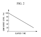
- FIG. 2 is a graph showing a function for deriving a confidence level based on the elapsed time since the time at which a high-luminance region is identified.
- FIG. 3 is a flowchart for explaining the operation of the fluoroscopy apparatus in FIG. 1 .
- FIG. 5 is a flowchart for explaining a modification of the operation of the fluoroscopy apparatus in FIG. 1 .
- FIG. 6 is a graph showing a modification of the function for deriving the confidence level based on the elapsed time since the time at which the high-luminance region is identified.
- FIG. 7 is a diagram showing a modification of the combined image generated by the fluoroscopy apparatus in FIG. 1 .
- FIG. 8 is an overall configuration diagram of a fluoroscopy apparatus according to a second embodiment of the present invention.
- FIG. 9 is a diagram showing a hue space whose axes are the confidence level based on the elapsed time and the confidence level based on the amount of movement.
- FIG. 10 is a diagram showing modifications of the combined images generated by the fluoroscopy apparatus in FIG. 8 .
- FIG. 11 is a graph showing another modification of the function for deriving the confidence level based on the elapsed time since the time at which the high-luminance region is identified.
- FIG. 12 is an overall configuration diagram showing another modification of the fluoroscopy apparatus in FIG. 1 .
- FIG. 13 is a graph showing a function for deriving the confidence level based on the product of the elapsed time since the time at which the high-luminance region is identified and the excitation light intensity.
- a fluoroscopy apparatus 1 according to a first embodiment of the present invention will be described below with reference to FIGS. 1 to 7 .
- the fluoroscopy apparatus 1 is an endoscope apparatus and is provided with a long, thin inserted portion 2 that is inserted into a body; a light source 3 ; an illumination unit 4 that radiates excitation light and white light (reference light) from the light source 3 toward an observation subject X from a distal end 2 a of the inserted portion 2 ; an image-acquisition unit 5 that is provided at the distal end 2 a of the inserted portion 2 and that acquires image information S 1 and S 2 about biological tissue, that is, the observation subject X; an image processing unit 6 that is disposed at the base end of the inserted portion 2 and that processes the image information S 1 and S 2 acquired by the image-acquisition unit 5 ; and a display portion 7 that displays a combined image G processed by the image processing unit 6 .
- the light source 3 is provided with a xenon lamp 31 , a filter 32 that extracts the excitation light and white light (illumination light: wavelength band from 400 nm to 740 nm) from light emitted from the xenon lamp 31 , and a coupling lens 33 that focuses the excitation light and white light extracted by the filter 32 .
- the illumination unit 4 is provided with a light-guide fiber 41 that is disposed over nearly the entire length of the inserted portion 2 in the longitudinal direction thereof, and an illumination optical system 42 provided at the distal end 2 a of the inserted portion 2 .
- the light-guide fiber 41 guides the excitation light and the white light focused by the coupling lens 33 .
- the illumination optical system 42 spreads out and radiates the excitation light and white light guided thereto by the light-guide fiber 41 onto the observation subject X facing the distal end 2 a of the inserted portion 2 .
- the image-acquisition unit 5 is provided with an objective lens 51 that collects light returning from a predetermined observation area of the observation subject X; a dichroic mirror 52 that, of the light collected by the objective lens 51 , reflects light having a wavelength equal to or greater than the excitation wavelength (excitation light and fluorescence) and allows white light (return light) having a shorter wavelength than the excitation wavelength to pass therethrough; two focusing lenses 53 and 54 that focus the fluorescence reflected by the dichroic mirror 52 and the white light that has passed through the dichroic mirror 52 , respectively; and two image-acquisition devices 55 and 56 , like CCDs or CMOS devices, that capture the white light and the fluorescence focused by the focusing lenses 53 and 54 .
- the image-acquisition devices 55 and 56 acquire white-light image information S 1 and fluorescence image information S 2 , respectively.
- reference sign 57 indicates an excitation light cut filter that blocks the excitation light in the light reflected by the dichroic mirror 52 (it allows only the light having, for example, a wavelength band from 760 nm to 850 nm, to pass therethrough).
- the image processing unit 6 is provided with a white-light image generating portion (reference-image generating portion) 61 that generates a white-light image (reference image) G 1 from the white-light image information S 1 acquired by the image-acquisition device 55 ; a fluorescence-image generating portion 62 that generates a fluorescence image G 2 from the fluorescence image information S 2 acquired by the image-acquisition device 56 ; an identifying portion 63 that, from the fluorescence image G 2 generated by the fluorescence-image generating portion 62 , identifies the positions of pixels having luminance values equal to or greater than a threshold set in advance; a storage portion 64 that stores the positions of the pixels identified by the identifying portion 63 ; a confidence-level calculating portion (detecting portion) 65 that calculates the confidence level of properties possessed by the pixels identified by the identifying portion 63 ; a marking-image generating portion (display-image generating portion) 66 that generates a marking image (display image) G 3 having hues in
- the identifying portion 63 compares luminance values of individual pixels of the fluorescence image G 2 input thereto from the fluorescence-image generating portion 62 with the predetermined threshold, identifies pixels having luminance values equal to or greater than the predetermined threshold as high-luminance regions P, and outputs the positions of the identified pixels to the storage portion 64 . In addition, the identifying portion 63 outputs a trigger signal to the confidence-level calculating portion 65 at the same time as it outputs the positions of the pixels to the storage portion 64 .
- the storage portion 64 stores pixel positions input from the identifying portion 63 . Each time new pixel positions are input from the identifying portion 63 , the storage portion 64 updates the pixel positions stored up to that point with the new pixel positions. By doing so, the storage portion 64 stores the most recent positions of the high-luminance regions P. The storage portion 64 outputs the pixel positions to the marking-image generating portion 66 at the update timing.
- the confidence-level calculating portion 65 has a timer, and, upon receiving the input of the trigger signal from the identifying portion 63 , it starts measuring time with the timer by using that input as a trigger. Then, the confidence-level calculating portion 65 calculates the confidence level of the properties of the high-luminance regions P based on the elapsed time (amount of change) measured by the timer. By doing so, the confidence level is calculated for the properties of the high-luminance regions P that can change due to the passage of time (physical quantity), such as, for example, the positions and luminance values of the high-luminance regions P. The confidence-level calculating portion 65 outputs the calculated confidence level to the marking-image generating portion 66 .
- the confidence level of the properties of the high-luminance regions P is calculated in accordance with a function that linearly decreases with an increase in the elapsed time. By doing so, it is possible to calculate the confidence level of the property of the high-luminance region P by means of a simple calculation.
- the slope of this function may be arbitrarily set by a user or it may be set based on the relationship measured in advance between the elapsed time and the amount of change in the positions of the high-luminance regions P.
- the marking-image generating portion 66 holds a hue scale in which the confidence level and hue are associated with each other. From the hue scale, the marking-image generating portion 66 selects a hue that corresponds to the confidence level input from the confidence-level calculating portion 65 and generates the marking image G 3 by applying the selected hue to the pixel positions input from the storage portion 64 .
- the inserted portion 2 is inserted into the body, and the distal end 2 a of the inserted portion 2 is made to face the observation subject X. Then, the excitation light and the white light are generated by activating the light source 3 and are made to enter the light-guide fiber 41 by means of the coupling lens 33 . The excitation light and the white light that have reached the distal end 2 a of the inserted portion 2 by being guided through the light-guide fiber 41 are spread out and radiated onto the observation subject X by the illumination optical system 42 .
- a fluorescent substance contained inside the observation subject X is excited by the excitation light, thus generating fluorescence, and the white light is also reflected at a surface of the observation subject X.
- the fluorescence and the reflected white light return to the distal end 2 a of the inserted portion 2 from the observation subject X, and the fluorescence and the white light generated in the observation area, representing a portion of the observation subject X, are collected by the objective lens 51 .
- FIG. 3 shows a flowchart for explaining processing performed by the fluoroscopy apparatus 1 according to this embodiment for generating the combined image G.
- the fluorescence and the white light collected by the objective lens 51 are split by the dichroic mirror 52 in accordance with the wavelengths thereof; for example, the white light in the wavelength band from 400 nm to 700 nm is focused by the focusing lens 54 and is acquired by the image-acquisition device 55 in the form of the white-light image information S 1 (Step S 1 ).
- the dichroic mirror 52 for example, light in the wavelength band from 700 nm to 850 nm, including the excitation light and the fluorescence in the fluorescence and the white light collected by the objective lens 51 , only the fluorescence is focused by the focusing lens 53 , after removing the excitation light (for example, light at 740 nm or less) by the excitation light cut filter 57 , and the fluorescence is acquired by the image-acquisition device 56 in the form of the fluorescence image information S 2 (Step S 1 ).
- the excitation light for example, light at 740 nm or less
- the image information S 1 and S 2 acquired by the individual image-acquisition devices 55 and 56 is transmitted to the image processing unit 6 .
- the white-light image information S 1 is input to the white-light image generating portion 61 , where the white-light image G 1 is generated (Step S 2 ).
- the fluorescence image information S 2 is input to the fluorescence-image generating portion 62 , where the fluorescence image G 2 is generated (Step S 2 ).
- the generated fluorescence image G 2 is transmitted to the identifying portion 63 , and the positions of the high-luminance regions P having luminance values equal to or greater than the predetermined threshold are identified (Step S 3 ). If high-luminance regions P do not exist (NO in Step S 3 ), the white-light image G 1 is displayed on the display portion 7 as the combined image G without modification (Step S 9 ), and the process returns to Step S 1 .
- the identified positions of the high-luminance regions P are output to the storage portion 64 from the identifying portion 63 and are stored in the storage portion 64 (Step S 4 ).
- the trigger signal is output to the confidence-level calculating portion 65 from the identifying portion 63 ; the timer at the confidence-level calculating portion 65 starts to measure the elapsed time (Steps S 5 and S 6 ); the confidence level of the properties of the high-luminance regions P are calculated from the measured elapsed time (Step S 7 ); and the calculated confidence level is output to the marking-image generating portion 66 .
- the marking image G 3 having hues corresponding to the confidence level input from the confidence-level calculating portion 65 at the positions of the high-luminance regions P is generated (Step S 8 ).
- N is a number that indicates the order of the fluorescence images G 2 in which the high-luminance regions P are identified.
- N remains 0 until a high-luminance region P is identified for the first time after the acquisition of the image information S 1 and S 2 has started, and thus, processing from Steps S 4 to S 8 is not performed during this time. Subsequently, processing from Steps S 4 to S 8 is started when a high-luminance region P is identified, and N is incremented each time a high-luminance region P is identified in the fluorescence images G 2 .
- the white-light image G 1 transmitted thereto from the white-light image generating portion 61 is superimposed on the marking image G 3 (Step S 9 ), and the generated combined image G is output to the display portion 7 from the image combining portion 67 .
- the hues of the high-luminance regions P in the combined image G change over time with a decrease over time in the confidence level calculated by the confidence-level calculating portion 65 , as shown in (a) to (c) in FIG. 4 .
- Different hatching directions in (a) to (d) in FIG. 4 indicate different hues.
- (a) to (d) in FIG. 4 show combined images G captured by causing a liquid containing a fluorescent substance to flow in a ureter (see broken line) existing in the observation subject X.
- Step S 4 when new high-luminance regions P are identified by the identifying portion 63 (YES in Step S 3 ), by updating the positions of the high-luminance regions P stored in the storage portion 64 (Step S 4 ), the positions of the high-luminance regions P in the combined image G are updated to the most recent positions, as shown in (d) in FIG. 4 .
- the elapsed time measured by the timer at the confidence-level calculating portion 65 is reset to zero, and thus, the confidence level is calculated to be 100%, which also restores the hues of the high-luminance regions P to the initial hue; if high-luminance regions P are not identified thereafter, the hues of the high-luminance regions P change over time.
- the high-luminance regions P are identified intermittently due to a discontinuous flow of the liquid in the ureter. In this way, when there is a gap in time between the last time the high-luminance regions P are identified and the next time the high-luminance regions P are identified, the high-luminance regions P identified last time continue to be displayed in the combined image G.
- the positions of the high-luminance regions P displayed in the current combined image G may become shifted from the actual positions of the high-luminance regions P due to relative positional shifting between the distal end 2 a of the inserted portion 2 and the observation subject X.
- the confidence level of the positions of the high-luminance regions P which decreases with the elapsed time since the time at which the positions of the high-luminance regions P are identified, is reflected in the hues of the high-luminance regions P.
- a user can recognize the degree by which the positions of the high-luminance regions P displayed in the current combined image G may possibly be shifted from the actual positions of the high-luminance regions P based on the hues thereof, and thus, he/she can properly interpret the positions of the high-luminance regions P displayed in the current combined image G.
- the marking-image generating portion 66 in this embodiment may hold a saturation scale in which the confidence level is associated with the saturation or a brightness scale in which the confidence level is associated with the brightness, and the marking-image generating portion 66 may select the saturation or the brightness that corresponds to the confidence level.
- the saturation or the brightness of the high-luminance regions P in the combined image G changes in accordance with the confidence level.
- the confidence-level calculating portion 65 in this embodiment resets the elapsed time measured by the timer to zero each time a new trigger signal is input from the identifying portion 63 and restarts the measurement of time from zero; alternatively, however, the measurement of time may be restarted from zero in accordance with an instruction from the user (Step S 10 ), as shown in FIG. 5 .
- Step S 10 an instruction from the user
- a function that linearly decreases with an increase in the elapsed time is used as the function for deriving the confidence level
- the user can set an appropriate function in advance.
- a different function may be set for each portion of the observation subject X.
- FIG. 6 as portions of the observation subject X, a tumor and a ureter to be surgically observed are shown.
- the degree by which the confidence level decreases for the same amount of elapsed time may be higher than in the case where the tumor is observed. Accordingly, for example, if the display mode is such that the confidence level is lower when the user treats the peripheries of the ureter, the user can temporarily stop the treatment and restart the treatment the next time the fluorescence from the ureter is observed and the confidence level is reset to 100%. Accordingly, it becomes possible to perform the treatment always in a state in which the confidence level is high based on the display mode.
- the fluoroscopy apparatus 1 is provided with an input portion (not shown) in which the user specifies portions of the observation subject X, and a function for the observation subject X specified via the input portion is used for calculating the confidence level.
- the storage portion 64 may sequentially and continuously store the positions of the high-luminance regions P input from the identifying portion 63 for a predetermined number of times (for example, ten times), the storage portion 64 may output all of the stored positions of the high-luminance regions P to the marking-image generating portion 66 , and the marking-image generating portion 66 may generate marking images G 3 having hues in accordance with the confidence level at all of the positions of the high-luminance regions P input from the storage portion 64 .
- marking images G 3 in which the movement paths thereof are shown as high-luminance regions P are generated, as shown in FIG. 7 . Therefore, in the marking images G 3 , it is easy to identify the shape of an organ in which a fluorescent substance has moved, such as the ureter.
- the fluoroscopy apparatus 100 differs from the fluoroscopy apparatus 1 according to the first embodiment in that the image processing unit 6 is provided with a feature-region identifying portion 68 that identifies a feature region of the observation subject X in the white-light image G 1 , and that the confidence-level calculating portion 65 calculates the confidence level in consideration of an amount of movement (amount of change) of relative positions (physical quantity) between the observation subject X and the distal end 2 a of the inserted portion 2 , instead of the elapsed time measured by the timer, or in addition to the elapsed timer. Therefore, in this embodiment, processing performed by the feature-region identifying portion 68 and the confidence-level calculating portion 65 will mainly be described, and description of the configuration in common with the first embodiment will be omitted.
- the feature-region identifying portion 68 stores a region in which specific tissue or the like is captured in the white-light image G 1 input from the white-light image generating portion 61 as a feature region. Then, by comparing a new white-light image G 1 input from the white-light image generating portion 61 and the stored feature region, the feature-region identifying portion 68 detects the position of the feature region in that white-light image G 1 , and outputs the position of the detected feature region to the confidence-level calculating portion 65 .
- the confidence-level calculating portion 65 time sequentially stores the position of the feature region input from the feature-region identifying portion 68 . Then, the confidence-level calculating portion 65 sequentially calculates the amount of movement in the position of the feature region by using the time at which the trigger signal is input from the identifying portion 63 as a starting point, and calculates the confidence level from the calculated amount of movement. The confidence level at this time is calculated in accordance with, for example, a function in which the confidence level linearly decreases with an increase in the amount of movement. The confidence-level calculating portion 65 outputs the calculated confidence level to the marking-image generating portion 66 .
- the marking-image generating portion 66 selects a hue that corresponds to the confidence level from a hue scale in which the confidence level calculated from the amount of movement is associated with the hue. By doing so, a combined image G having hues corresponding to the confidence level based on the amount of movement of the observation subject X at the positions of the high-luminance regions P is generated. Note that, as with the first embodiment, the marking-image generating portion 66 may set, instead of the hue, the saturation or the brightness in correspondence with the confidence level.
- the confidence-level calculating portion 65 may calculate the confidence level as being 0%. By doing so, it is possible to allow the user to quickly recognize that the confidence level of the property of the high-luminance region P has sufficiently deteriorated.
- the confidence-level calculating portion 65 should calculate one confidence level based on the elapsed time and another based on the amount of movement, and, among hue, brightness, and saturation, the confidence-level calculating portion 65 should set two of them for the high-luminance regions P, based on the two confidence levels.
- the hue of the high-luminance regions P should be set from the confidence level based on the elapsed time
- the brightness of the high-luminance regions P should be set from the confidence level based on the amount of movement
- a combined image G having the determined hue and brightness at the positions of the high-luminance regions P should be generated.
- the confidence-level calculating portion 65 may select a hue at a position determined based on the elapsed time measured by the timer and the calculated amount of movement.
- the confidence level of the positions and luminance values of the high-luminance regions P are shown by two types of information in the combined image G, and thus, it is possible to allow the user to recognize even more accurate confidence level of the positions and luminance values of the high-luminance regions P.
- different pitches of hatching indicate differences in the brightness.
- the feature-region identifying portion 68 may identify the position of a feature region in a Narrow Band Imaging (NBI) image, instead of the white-light image G 1 .
- NBI Narrow Band Imaging
- the fluoroscopy apparatus 100 irradiates the observation subject X with blue and green light having sufficiently narrow wavelength bands, and is provided with another image-acquisition device that detects reflected light of these light beams coming from the observation subject X, as well as an NBI-image generating portion.
- the positions of the high-luminance regions P in the combined image G may be made to follow the movement of the feature region.
- the marking-image generating portion 66 receives the amount of movement of the feature region from the confidence-level calculating portion 65 , moves the positions of the high-luminance regions P input from the storage portion 64 by the same amount as the amount of movement of the feature region, and generates a marking image G 3 by applying the hues to the destination positions.
- the marking-image generating portion 66 receives the amount of movement of the feature region from the confidence-level calculating portion 65 , moves the positions of the high-luminance regions P input from the storage portion 64 by the same amount as the amount of movement of the feature region, and generates a marking image G 3 by applying the hues to the destination positions.
- the confidence-level calculating portion 65 may store the feature region identified by the feature-region identifying portion 68 and the elapsed time in association with each other at the timing when the trigger signal is input from the identifying portion 63 , and, thereafter, the confidence-level calculating portion 65 may measure the elapsed time only when the stored feature region is identified in the white-light image G 1 .
- an independent elapsed time can be calculated for each target portion. Furthermore, when the feature region falls outside the viewing field of the white-light image G 1 , the measurement of the elapsed time is temporarily stopped, and the measurement of the elapsed time is restarted when the feature region appears again in the viewing field of the white-light image G 1 ; therefore, it is possible to measure accurate elapsed time for the individual target portions.
- Step S 10 instead of judging whether or not there is an update instruction from the user (Step S 10 ), it is judged whether or not the feature region identified by the feature-region identifying portion 68 matches with the feature regions that are already stored. Then, when there is a match, the process advances to Step S 7 after restarting the measurement of the elapsed time associated with the matching feature region among the stored feature regions. On the other hand, there is no match, the process advances to Step S 4 , and the identified feature region should newly be stored together with the positions of the high-luminance regions P.
- the confidence-level calculating portion 65 may calculate the confidence level in accordance with a function based on bleaching characteristic of the fluorescent substance. In other words, by determining the relationship between the fluorescence intensity and the elapsed time since the time at which the irradiation of the fluorescent substance with the excitation light is started, a graph of the bleaching characteristic of the fluorescent substance is obtained, and the fluorescence intensity normalized by assuming the elapsed time in this graph to be the elapsed time measured by the timer and by assuming the fluorescence intensity at the time when irradiation with the excitation light is started to be 100% should be used as the confidence level.
- the confidence-level calculating portion 65 continues to accumulate the elapsed time measured by the timer while the high-luminance regions P are being identified, without resetting the timer.
- the marking-image generating portion 66 generates a marking image G 3 having luminance values in accordance with the confidence level calculated by the confidence-level calculating portion 65 at the positions of the high-luminance regions P.
- the functions based on the bleaching characteristic are set for a plurality of fluorescent substances F 1 , F 2 , and F 3 , and the configuration of the present invention may be such that the function to be used for calculating the confidence level is selected by the user specifying the fluorescent substance to be used by using an input portion (not shown).
- the fluoroscopy apparatuses 1 and 100 may be configured so that the user can reset the elapsed time of the timer in the confidence-level calculating portion 65 .
- an excitation-light-intensity detecting portion 69 that detects the excitation light intensity may be provided, and the confidence-level calculating portion 65 may calculate the confidence level based on a product of the elapsed time measured by the timer and the excitation light intensity detected by the excitation-light-intensity detecting portion 69 .
- FIG. 12 shows an example in which the excitation-light-intensity detecting portion 69 is applied to the configuration of the fluoroscopy apparatus 1 of the first embodiment.
- the excitation-light-intensity detecting portion 69 is provided with, for example, a half mirror that is provided between the filter 32 and the coupling lens 33 and that splits off a portion of the excitation light and a light-level meter that detects the light level of the portion of the excitation light split off by the half mirror.
- FIG. 13 shows a function for deriving the confidence level from the product of the elapsed time and the excitation light intensity. Because the fluorescence intensity attenuates in accordance with the accumulated light level of the excitation light with which the fluorescent substance is irradiated, by calculating the confidence level from the product of the elapsed time and the excitation light intensity and by applying the luminance values based on the calculated confidence level to the positions of the high-luminance regions P, the present invention allows the user to recognize even more accurate fluorescence intensity at the actual high-luminance regions P.
- the excitation-light-intensity detecting portion 69 may detect the intensity of the white light. Because there is a correlation between the intensities of the white light and the excitation light emitted from the same xenon lamp 31 , it is possible to obtain the same effect as when the excitation light intensity is used. In this case, it is preferable that the intensity of the white light reflected at the observation subject X be detected as the intensity of the white light. In other words, the luminance value of the white-light image G 1 should be detected as the intensity of the white light.
- the configurations thereof may be such that the identification of the high-luminance regions P by the identifying portion 63 is started in response to an instruction from the user.
- a user interface (not shown), such as a touch panel or the like, through which the user can input instructions related to the marking region and instructions for starting to generate the marking image G 3 may be provided.
- Steps S 3 to S 8 are performed at arbitrary timing selected by the user, and thus, it is possible to reduce the amount of calculation by generating the marking image G 3 only when the user needs it.
- the configurations thereof may be such that, when the confidence level falls below a predetermined threshold, for example, 50%, the high-luminance regions P in the combined image G are displayed in a flashing manner so as to allow the user to reliably recognize the deterioration of the confidence level.
- a predetermined threshold for example, 50%
- a switch that allows the user to switch between displaying and hiding the high-luminance regions P in the combined image G may be provided.
Landscapes
- Life Sciences & Earth Sciences (AREA)
- Health & Medical Sciences (AREA)
- Surgery (AREA)
- Engineering & Computer Science (AREA)
- Biophysics (AREA)
- Public Health (AREA)
- Veterinary Medicine (AREA)
- Physics & Mathematics (AREA)
- Pathology (AREA)
- General Health & Medical Sciences (AREA)
- Animal Behavior & Ethology (AREA)
- Biomedical Technology (AREA)
- Heart & Thoracic Surgery (AREA)
- Medical Informatics (AREA)
- Molecular Biology (AREA)
- Radiology & Medical Imaging (AREA)
- Optics & Photonics (AREA)
- Nuclear Medicine, Radiotherapy & Molecular Imaging (AREA)
- Signal Processing (AREA)
- Investigating, Analyzing Materials By Fluorescence Or Luminescence (AREA)
- Instruments For Viewing The Inside Of Hollow Bodies (AREA)
- Microscoopes, Condenser (AREA)
- Endoscopes (AREA)
Abstract
Description
- {Patent Literature 1} Publication of Japanese Patent No. 3771985
- 1, 100 fluoroscopy apparatus
- 2 inserted portion
- 2 a distal end
- 3 light source
- 31 xenon lamp
- 32 filter
- 33 coupling lens
- 4 illumination unit
- 41 light-guide fiber
- 42 illumination optical system
- 5 image-acquisition unit
- 51 objective lens
- 52 dichroic mirror
- 53, 54 focusing lens
- 55, 56 image-acquisition device
- 57 excitation light cut filter
- 6 image processing unit
- 61 white-light image generating portion (reference-image generating portion)
- 62 fluorescence-image generating portion
- 63 identifying portion
- 64 storage portion
- 65 confidence-level calculating portion (detecting portion)
- 66 marking-image generating portion (display-image generating portion)
- 67 image combining portion
- 68 feature-region identifying portion
- 69 excitation-light-intensity detecting portion
- 7 display portion
- X observation subject
- G1 white-light image (reference image)
- G2 fluorescence image
- G3 marking image (display image)
- G combined image
- P high-luminance region
Claims (14)
Applications Claiming Priority (2)
| Application Number | Priority Date | Filing Date | Title |
|---|---|---|---|
| JP2012164924A JP5993237B2 (en) | 2012-07-25 | 2012-07-25 | Fluorescence observation equipment |
| JP2012-164924 | 2012-07-25 |
Publications (2)
| Publication Number | Publication Date |
|---|---|
| US20140028824A1 US20140028824A1 (en) | 2014-01-30 |
| US9332909B2 true US9332909B2 (en) | 2016-05-10 |
Family
ID=49994510
Family Applications (1)
| Application Number | Title | Priority Date | Filing Date |
|---|---|---|---|
| US13/942,933 Active 2034-08-24 US9332909B2 (en) | 2012-07-25 | 2013-07-16 | Fluoroscopy apparatus |
Country Status (3)
| Country | Link |
|---|---|
| US (1) | US9332909B2 (en) |
| JP (1) | JP5993237B2 (en) |
| CN (1) | CN103565411B (en) |
Families Citing this family (20)
| Publication number | Priority date | Publication date | Assignee | Title |
|---|---|---|---|---|
| US9427506B2 (en) * | 2010-03-31 | 2016-08-30 | Kci Licensing, Inc. | System and method for locating fluid leaks at a drape using sensing techniques |
| CN103561626B (en) * | 2011-06-03 | 2015-12-02 | 奥林巴斯株式会社 | Fluorescence observation device and fluorescence observation method |
| EP3141178A4 (en) * | 2014-11-26 | 2018-02-21 | Olympus Corporation | Diagnosis assistance device and diagnosis assistance information display method |
| DE112015006295T5 (en) * | 2015-04-06 | 2017-11-30 | Olympus Corporation | Image processing apparatus, biological observation apparatus and image processing method |
| GB201507454D0 (en) | 2015-04-30 | 2015-06-17 | Phase Focus Ltd | Method and apparatus for determining temporal behaviour of an object |
| WO2016203572A1 (en) * | 2015-06-17 | 2016-12-22 | オリンパス株式会社 | Imaging apparatus |
| WO2017047497A1 (en) * | 2015-09-14 | 2017-03-23 | 日本化薬株式会社 | Polymer conjugate of hexa-coordinated platinum complex |
| WO2017073338A1 (en) * | 2015-10-26 | 2017-05-04 | オリンパス株式会社 | Endoscope image processing device |
| EP3360461A4 (en) * | 2015-11-10 | 2019-05-08 | Olympus Corporation | Endoscope device |
| JP2017134115A (en) * | 2016-01-25 | 2017-08-03 | オリンパス株式会社 | Microscope device, and image display program |
| WO2017199757A1 (en) * | 2016-05-16 | 2017-11-23 | ソニー株式会社 | Optical device and information processing method |
| JP6645591B2 (en) * | 2017-01-11 | 2020-02-14 | 株式会社島津製作所 | Fluorescence imaging device and fluorescence imaging system |
| JP6967906B2 (en) * | 2017-08-04 | 2021-11-17 | Hoya株式会社 | Endoscope shape display device and endoscope system |
| JP6899276B2 (en) * | 2017-08-04 | 2021-07-07 | Hoya株式会社 | Endoscope shape display device, endoscope system |
| WO2019093089A1 (en) * | 2017-11-13 | 2019-05-16 | ソニー株式会社 | Information processing device, information processing method, and fluorescence image capturing system |
| CN108055454B (en) * | 2017-12-08 | 2020-07-28 | 合肥工业大学 | Architecture and image processing method of medical endoscope artificial intelligence chip |
| JP7281308B2 (en) * | 2019-03-07 | 2023-05-25 | ソニー・オリンパスメディカルソリューションズ株式会社 | Medical image processing device and medical observation system |
| WO2021003578A1 (en) * | 2019-07-10 | 2021-01-14 | Novadaq Technologies ULC | Systems and methods for persistent ureter visualization |
| CN116249504B (en) * | 2020-09-29 | 2025-11-28 | 奥林巴斯株式会社 | Auxiliary device, endoscope system, auxiliary method, and storage medium |
| WO2022245450A1 (en) * | 2021-05-17 | 2022-11-24 | Stryker Corporation | Medical imaging |
Citations (6)
| Publication number | Priority date | Publication date | Assignee | Title |
|---|---|---|---|---|
| US20040109231A1 (en) * | 2002-08-28 | 2004-06-10 | Carl-Zeiss-Stiftung Trading As Carl Zeiss | Microscopy system, microscopy method and a method of treating an aneurysm |
| US20060074893A1 (en) * | 2002-08-26 | 2006-04-06 | Koninklijke Philips Electronics N.V. | Unit for and method of detection a content property in a sequence of video images |
| JP3771985B2 (en) | 1997-01-20 | 2006-05-10 | オリンパス株式会社 | Fluorescence observation endoscope device |
| US20070250274A1 (en) * | 2006-02-06 | 2007-10-25 | Visigen Biotechnologies, Inc. | Method for analyzing dynamic detectable events at the single molecule level |
| US20090305287A1 (en) * | 2005-06-10 | 2009-12-10 | Life Technologies Corporation | Method and System for Multiplex Genetic Analysis |
| US20120248333A1 (en) * | 2011-03-30 | 2012-10-04 | Johannes Fallert | Device For Fluorescence Diagnosis |
Family Cites Families (12)
| Publication number | Priority date | Publication date | Assignee | Title |
|---|---|---|---|---|
| JP3884265B2 (en) * | 2001-10-22 | 2007-02-21 | オリンパス株式会社 | Endoscope device |
| KR100411631B1 (en) * | 2001-10-18 | 2003-12-18 | 주식회사 메디미르 | Fluorescence endoscope apparatus and a method for imaging tissue within a body using the same |
| JP4249103B2 (en) * | 2003-08-08 | 2009-04-02 | オリンパス株式会社 | Fluorescence lifetime measuring device |
| JP5044126B2 (en) * | 2006-02-23 | 2012-10-10 | オリンパス株式会社 | Endoscope observation apparatus and operation method of endoscope for image formation |
| JP5081720B2 (en) * | 2008-05-22 | 2012-11-28 | 富士フイルム株式会社 | Fluorescence endoscope apparatus and excitation light unit |
| JP5294723B2 (en) * | 2008-06-26 | 2013-09-18 | 富士フイルム株式会社 | Image acquisition device |
| JP5415805B2 (en) * | 2009-03-31 | 2014-02-12 | オリンパスメディカルシステムズ株式会社 | Diagnosis support device |
| JP5658873B2 (en) * | 2009-11-13 | 2015-01-28 | オリンパス株式会社 | Image processing apparatus, electronic apparatus, endoscope system, and program |
| JP5555002B2 (en) * | 2010-02-10 | 2014-07-23 | オリンパス株式会社 | Fluorescence endoscope device |
| JP5763893B2 (en) * | 2010-06-08 | 2015-08-12 | 富士フイルム株式会社 | Image processing system and program, and operation method of endoscope system |
| JP5637783B2 (en) * | 2010-08-31 | 2014-12-10 | 富士フイルム株式会社 | Image acquisition apparatus and operation method thereof |
| JP2012090889A (en) * | 2010-10-28 | 2012-05-17 | Olympus Corp | Fluorescence observation device |
-
2012
- 2012-07-25 JP JP2012164924A patent/JP5993237B2/en not_active Expired - Fee Related
-
2013
- 2013-07-16 CN CN201310297972.7A patent/CN103565411B/en not_active Expired - Fee Related
- 2013-07-16 US US13/942,933 patent/US9332909B2/en active Active
Patent Citations (6)
| Publication number | Priority date | Publication date | Assignee | Title |
|---|---|---|---|---|
| JP3771985B2 (en) | 1997-01-20 | 2006-05-10 | オリンパス株式会社 | Fluorescence observation endoscope device |
| US20060074893A1 (en) * | 2002-08-26 | 2006-04-06 | Koninklijke Philips Electronics N.V. | Unit for and method of detection a content property in a sequence of video images |
| US20040109231A1 (en) * | 2002-08-28 | 2004-06-10 | Carl-Zeiss-Stiftung Trading As Carl Zeiss | Microscopy system, microscopy method and a method of treating an aneurysm |
| US20090305287A1 (en) * | 2005-06-10 | 2009-12-10 | Life Technologies Corporation | Method and System for Multiplex Genetic Analysis |
| US20070250274A1 (en) * | 2006-02-06 | 2007-10-25 | Visigen Biotechnologies, Inc. | Method for analyzing dynamic detectable events at the single molecule level |
| US20120248333A1 (en) * | 2011-03-30 | 2012-10-04 | Johannes Fallert | Device For Fluorescence Diagnosis |
Non-Patent Citations (1)
| Title |
|---|
| English Abstract only of corresponding JP 10-201700, dated Aug. 4, 1998. |
Also Published As
| Publication number | Publication date |
|---|---|
| JP2014023628A (en) | 2014-02-06 |
| US20140028824A1 (en) | 2014-01-30 |
| CN103565411B (en) | 2017-03-01 |
| CN103565411A (en) | 2014-02-12 |
| JP5993237B2 (en) | 2016-09-14 |
Similar Documents
| Publication | Publication Date | Title |
|---|---|---|
| US9332909B2 (en) | Fluoroscopy apparatus | |
| US9392942B2 (en) | Fluoroscopy apparatus and fluoroscopy system | |
| US9532719B2 (en) | Fluorescence endoscope apparatus | |
| US9417188B2 (en) | Fluorescence observation device | |
| US9241139B2 (en) | Fluorescence observation device | |
| US9516235B2 (en) | Fluorescence observation apparatus and fluorescence observation method | |
| US9513219B2 (en) | Fluoroscopy apparatus and image display method therefor | |
| US8421034B2 (en) | Fluoroscopy apparatus and fluorescence image processing method | |
| US9498109B2 (en) | Fluorescence endoscope device | |
| CN102753080B (en) | Fluorescence endoscope device | |
| US9313388B2 (en) | Fluorescence observation device | |
| US20170086659A1 (en) | Diagnosis assisting apparatus and diagnosis assisting information display method | |
| CN105934191B (en) | Fluorescence monitoring apparatus | |
| US20130250079A1 (en) | Fluorescence endoscope apparatus | |
| CN104010558A (en) | Fluorescence observation device, fluorescence observation method, and working method of fluorescence observation device | |
| JP5346635B2 (en) | Fluorescence observation equipment | |
| JP6266559B2 (en) | Endoscope diagnosis apparatus, image processing method, program, and recording medium | |
| KR20190061337A (en) | Non-radiation based disease tissue detection medical imaging apparatus and methods |
Legal Events
| Date | Code | Title | Description |
|---|---|---|---|
| AS | Assignment |
Owner name: OLYMPUS MEDICAL SYSTEMS CORP., JAPAN Free format text: ASSIGNMENT OF ASSIGNORS INTEREST;ASSIGNORS:KUBO, KEI;ISHIHARA, YASUSHIGE;SHIDA, HIROMI;AND OTHERS;SIGNING DATES FROM 20130716 TO 20130719;REEL/FRAME:031185/0776 Owner name: OLYMPUS CORPORATION, JAPAN Free format text: ASSIGNMENT OF ASSIGNORS INTEREST;ASSIGNORS:KUBO, KEI;ISHIHARA, YASUSHIGE;SHIDA, HIROMI;AND OTHERS;SIGNING DATES FROM 20130716 TO 20130719;REEL/FRAME:031185/0776 |
|
| AS | Assignment |
Owner name: OLYMPUS CORPORATION, JAPAN Free format text: ASSIGNMENT OF ASSIGNORS INTEREST;ASSIGNOR:OLYMPUS MEDICAL SYSTEMS CORP.;REEL/FRAME:036276/0543 Effective date: 20150401 |
|
| AS | Assignment |
Owner name: OLYMPUS CORPORATION, JAPAN Free format text: CHANGE OF ADDRESS;ASSIGNOR:OLYMPUS CORPORATION;REEL/FRAME:038361/0303 Effective date: 20160401 |
|
| STCF | Information on status: patent grant |
Free format text: PATENTED CASE |
|
| MAFP | Maintenance fee payment |
Free format text: PAYMENT OF MAINTENANCE FEE, 4TH YEAR, LARGE ENTITY (ORIGINAL EVENT CODE: M1551); ENTITY STATUS OF PATENT OWNER: LARGE ENTITY Year of fee payment: 4 |
|
| MAFP | Maintenance fee payment |
Free format text: PAYMENT OF MAINTENANCE FEE, 8TH YEAR, LARGE ENTITY (ORIGINAL EVENT CODE: M1552); ENTITY STATUS OF PATENT OWNER: LARGE ENTITY Year of fee payment: 8 |