US9331783B2 - Method for compensating chromatic dispersion and associated equipment - Google Patents
Method for compensating chromatic dispersion and associated equipment Download PDFInfo
- Publication number
- US9331783B2 US9331783B2 US14/387,295 US201314387295A US9331783B2 US 9331783 B2 US9331783 B2 US 9331783B2 US 201314387295 A US201314387295 A US 201314387295A US 9331783 B2 US9331783 B2 US 9331783B2
- Authority
- US
- United States
- Prior art keywords
- optical
- packet
- channels
- band
- add
- Prior art date
- Legal status (The legal status is an assumption and is not a legal conclusion. Google has not performed a legal analysis and makes no representation as to the accuracy of the status listed.)
- Expired - Fee Related, expires
Links
Images


Classifications
-
- H—ELECTRICITY
- H04—ELECTRIC COMMUNICATION TECHNIQUE
- H04B—TRANSMISSION
- H04B10/00—Transmission systems employing electromagnetic waves other than radio-waves, e.g. infrared, visible or ultraviolet light, or employing corpuscular radiation, e.g. quantum communication
- H04B10/25—Arrangements specific to fibre transmission
- H04B10/2507—Arrangements specific to fibre transmission for the reduction or elimination of distortion or dispersion
- H04B10/2513—Arrangements specific to fibre transmission for the reduction or elimination of distortion or dispersion due to chromatic dispersion
-
- H—ELECTRICITY
- H04—ELECTRIC COMMUNICATION TECHNIQUE
- H04B—TRANSMISSION
- H04B10/00—Transmission systems employing electromagnetic waves other than radio-waves, e.g. infrared, visible or ultraviolet light, or employing corpuscular radiation, e.g. quantum communication
- H04B10/07—Arrangements for monitoring or testing transmission systems; Arrangements for fault measurement of transmission systems
- H04B10/075—Arrangements for monitoring or testing transmission systems; Arrangements for fault measurement of transmission systems using an in-service signal
- H04B10/079—Arrangements for monitoring or testing transmission systems; Arrangements for fault measurement of transmission systems using an in-service signal using measurements of the data signal
- H04B10/0795—Performance monitoring; Measurement of transmission parameters
- H04B10/07951—Monitoring or measuring chromatic dispersion or PMD
-
- H—ELECTRICITY
- H04—ELECTRIC COMMUNICATION TECHNIQUE
- H04B—TRANSMISSION
- H04B10/00—Transmission systems employing electromagnetic waves other than radio-waves, e.g. infrared, visible or ultraviolet light, or employing corpuscular radiation, e.g. quantum communication
- H04B10/25—Arrangements specific to fibre transmission
- H04B10/2507—Arrangements specific to fibre transmission for the reduction or elimination of distortion or dispersion
-
- H—ELECTRICITY
- H04—ELECTRIC COMMUNICATION TECHNIQUE
- H04B—TRANSMISSION
- H04B10/00—Transmission systems employing electromagnetic waves other than radio-waves, e.g. infrared, visible or ultraviolet light, or employing corpuscular radiation, e.g. quantum communication
- H04B10/60—Receivers
- H04B10/61—Coherent receivers
- H04B10/616—Details of the electronic signal processing in coherent optical receivers
- H04B10/6161—Compensation of chromatic dispersion
-
- H—ELECTRICITY
- H04—ELECTRIC COMMUNICATION TECHNIQUE
- H04J—MULTIPLEX COMMUNICATION
- H04J14/00—Optical multiplex systems
- H04J14/02—Wavelength-division multiplex systems
-
- H—ELECTRICITY
- H04—ELECTRIC COMMUNICATION TECHNIQUE
- H04J—MULTIPLEX COMMUNICATION
- H04J14/00—Optical multiplex systems
- H04J14/02—Wavelength-division multiplex systems
- H04J14/0201—Add-and-drop multiplexing
-
- H—ELECTRICITY
- H04—ELECTRIC COMMUNICATION TECHNIQUE
- H04J—MULTIPLEX COMMUNICATION
- H04J14/00—Optical multiplex systems
- H04J14/02—Wavelength-division multiplex systems
- H04J14/0201—Add-and-drop multiplexing
- H04J14/0202—Arrangements therefor
-
- H—ELECTRICITY
- H04—ELECTRIC COMMUNICATION TECHNIQUE
- H04J—MULTIPLEX COMMUNICATION
- H04J14/00—Optical multiplex systems
- H04J14/02—Wavelength-division multiplex systems
- H04J14/0201—Add-and-drop multiplexing
- H04J14/0202—Arrangements therefor
- H04J14/0209—Multi-stage arrangements, e.g. by cascading multiplexers or demultiplexers
-
- H—ELECTRICITY
- H04—ELECTRIC COMMUNICATION TECHNIQUE
- H04J—MULTIPLEX COMMUNICATION
- H04J14/00—Optical multiplex systems
- H04J14/02—Wavelength-division multiplex systems
- H04J14/0201—Add-and-drop multiplexing
- H04J14/0202—Arrangements therefor
- H04J14/021—Reconfigurable arrangements, e.g. reconfigurable optical add/drop multiplexers [ROADM] or tunable optical add/drop multiplexers [TOADM]
- H04J14/0212—Reconfigurable arrangements, e.g. reconfigurable optical add/drop multiplexers [ROADM] or tunable optical add/drop multiplexers [TOADM] using optical switches or wavelength selective switches [WSS]
-
- H—ELECTRICITY
- H04—ELECTRIC COMMUNICATION TECHNIQUE
- H04J—MULTIPLEX COMMUNICATION
- H04J14/00—Optical multiplex systems
- H04J14/02—Wavelength-division multiplex systems
- H04J14/0227—Operation, administration, maintenance or provisioning [OAMP] of WDM networks, e.g. media access, routing or wavelength allocation
- H04J14/0254—Optical medium access
- H04J14/0272—Transmission of OAMP information
- H04J14/0275—Transmission of OAMP information using an optical service channel
-
- H—ELECTRICITY
- H04—ELECTRIC COMMUNICATION TECHNIQUE
- H04J—MULTIPLEX COMMUNICATION
- H04J14/00—Optical multiplex systems
- H04J14/02—Wavelength-division multiplex systems
- H04J14/03—WDM arrangements
- H04J14/0305—WDM arrangements in end terminals
-
- H—ELECTRICITY
- H04—ELECTRIC COMMUNICATION TECHNIQUE
- H04J—MULTIPLEX COMMUNICATION
- H04J14/00—Optical multiplex systems
- H04J14/02—Wavelength-division multiplex systems
- H04J14/03—WDM arrangements
- H04J14/0307—Multiplexers; Demultiplexers
-
- H—ELECTRICITY
- H04—ELECTRIC COMMUNICATION TECHNIQUE
- H04Q—SELECTING
- H04Q11/00—Selecting arrangements for multiplex systems
- H04Q11/0001—Selecting arrangements for multiplex systems using optical switching
- H04Q11/0062—Network aspects
- H04Q11/0066—Provisions for optical burst or packet networks
Definitions
- the present invention relates to the field of wavelength division multiplexing optical networks with packet granularity capability and coherent detection and more particularly to the chromatic dispersion compensation in such networks.
- a wavelength division multiplexing optical network refers to a network comprising a plurality of nodes connected by optical links wherein data signals are transmitted through a plurality of channels having different wavelengths and which are multiplexed to be transmitted through the optical links of the network.
- Packet granularity or packet switching granularity refers to the possibility to add or drop one or several optical packets of a signal in an intermediary node while transmitting the other packets transparently.
- the packets are usually transmitted within time slots so that the packets of the different channels are synchronized.
- POADMs packet optical add-drop multiplexers
- a POADM requires compensating for the chromatic dispersion induced by the transmission of optical packets through links of the network.
- inter-channel chromatic dispersion refers to the fact that packets transmitted in channels of different wavelengths experience different travelling speeds so that time shifts or time offsets are introduced between packets emitted simultaneously. Need is then to resynchronize the packets to enable their processing at the receiver.
- intra-channel chromatic dispersion refers to the distortion undergone by the signal representing the bit coding of a packet during its transmission through the links of the network, rendering the bit decoding difficult and possibly erroneous.
- in-line compensators located along the links of the network.
- in-line components introduce additional losses that need to be compensated by additional amplifiers.
- amplifiers introduce additional costs and generate additional noise so that the distance that can be reached transparently with a given quality of signal may be reduced.
- the present invention refers to a method for compensating, within a node of an optical network, chromatic dispersion undergone by optical packets transmitted within time slots of wavelength division multiplexed channels along at least one link of the optical network, a time slot duration corresponding to the sum of a packet duration and an inter-packet gap duration, the said method comprising the followings steps:
- the embodiments of the present invention also refer to a packet optical add/drop multiplexer located in a node of a wavelength division multiplexing optical network and configured to process optical packets transmitted within time slots having a duration corresponding to a packet duration and an inter-packet gap duration along links of the optical network and received from remote nodes of the optical network, the said packet optical add/drop multiplexer comprising:
- FIG. 1 is a diagram of the arrangement of the packets in their time slots in the different channels of the different bands of a WDM signal
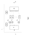
- FIG. 2 is a diagram of a packet optical add-drop multiplexer according to an embodiment of the present invention
- FIG. 3 is a diagram of a packet optical add-drop multiplexer according to another embodiment of the present invention.
- FIG. 4 is a diagram of a packet optical add-drop structure according to an embodiment of the present invention.
- FIG. 5 is a diagram of a coherent receiver according to an embodiment of the present invention.
- FIG. 6 is a diagram of multiple input multiple output adaptive equalizer with four finite impulse response (FIR) filters
- FIG. 7 is a diagram of a spectrum grid comprising a plurality of wavelength channels
- FIG. 8 is a diagram of the arrangements of the packets in the time slots of a wavelength channels
- FIG. 9 is a diagram of a network portion
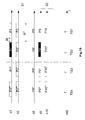
- FIG. 10 is a diagram of the packets in their time slots at the ingress node
- FIG. 11 is a diagram of the packets in their time slots at the input of an intermediary node
- FIG. 12 is a diagram of the packets in their time slots at the output of an intermediary node
- FIG. 13 is a diagram of the packets in their time slots at the input of an egress node
- FIG. 14 is a diagram of a node comprising a combination of ROADM and POADM according to a first embodiment
- FIG. 15 is a diagram of a node comprising a combination of ROADM and POADM according to a second embodiment
- the elements having the same reference correspond to elements having a similar function.
- the reference number represent a class of elements having a similar function while the index designate a particular element of the class.
- the elements 13 1 and 13 2 refer both to delay lines but the element 13 1 may have a delay that is different than the element 13 2 .
- WSS Wavelength Selective Switch
- ROADM refers to the acronym Reconfigurable Optical Add-Drop Multiplexer
- POADM Packet Optical Add-Drop Multiplexer
- SOA Semiconductor Optical Amplifier
- inter-packet gap in a packet stream refers to the guard interval which separates two consecutive packets transmitted on a common wavelength channel
- band refers to a wavelength interval, usually gathering a plurality of wavelength channels
- time slot in a packet stream transmitted in a channel refers to a time interval wherein a packet is inserted.
- the time slot duration corresponds to the sum of a packet duration and an inter-packet gap duration.
- FIR filter refers to the acronym Finite Impulse Response filter which is a filter whose impulse response (or response to any finite length input) is of finite duration.
- the terms “ingress node and egress node” of a signal refer respectively to the source node from which the signal is emitted (after being converted from the electrical to the optical domain) and the destination node in which the signal is received (and is converted from the optical to the electrical domain).
- the term “transparent” to qualify a path or a transmission refers to the transmission (or path) of an optical signal without performing any optical-electrical-optical (OEO) conversion.
- optical packet refers to an optical signal corresponding to a block of a predetermined amount of data (or predetermined number of bits) encoded according to a coding scheme and modulated according to a predetermined modulation format.
- the term “dropped packet” refers to a packet for which the current node is the egress node so that the said packet is detected by a receiver and the data of the packet are decoded by the receiver. Inversely, the non-dropped packets are transmitted transparently toward another node.
- Gb/s refers to the unit giga-bit per second.
- the embodiments of the present invention refer to a method for compensating chromatic dispersion undergone by packets transmitted in time slots of wavelength division multiplexed (WDM) channels through the links of a network wherein inter-channel and intra-channel chromatic dispersion are compensated in the nodes of the network and separately, the inter-channel chromatic dispersion being compensated thanks to delay lines while the intra-channel chromatic dispersion being compensated by digital signal processing techniques. Furthermore, an aspect of the present invention is to process the received WDM channels per band in order to reduce the capital expenditure required to implement the inter-channel chromatic dispersion compensation.
- WDM wavelength division multiplexed
- the method is based on coherent detection wherein the packets transmitted at different times by several channels can be detected by a single coherent receiver without requiring additional filtering elements.
- optical packets belonging to a common time slot are emitted simultaneously (with different transmitters) whereas optical packets belonging to different time slots (on the same or on different channels) are emitted at different times as described in FIG. 1 where a set of j wavelength channels ⁇ distributed in k bands B of i channels is represented.
- Each channel is timely divided into successive time slots TS of duration ⁇ T wherein the packets P are introduced.
- An additional channel ⁇ ct refers to the control channel that transmits the header of the packets P transmitted in the other channels ⁇ 1 . . . j than the control channel ⁇ ct.
- the control channel ⁇ ct is a circuit switching channel and therefore does not comprise packets but a continuous flow of data organized in frames T of length TS.
- time shifts or time offsets introduced between the channels by the effects of the inter-channel chromatic dispersion during transmission along the links of the network may lead to a temporal overlapping of the packets transmitted in different time slots through different channels.
- the introduced time shift is proportional to the wavelength difference of the channels, for adjacent channels having close wavelengths, herein the channels of a common band B, the introduced time offset remains very small.
- a packet stream transmitted within a channel comprises a succession of time slots, each time slot comprising a data packet and an inter-packet gap or guard interval which is used to separate two successive packets.
- each time slot comprising a data packet and an inter-packet gap or guard interval which is used to separate two successive packets.
- the number of channels that a coherent receiver is able to process without introducing too much loss is also limited, for example ten channels with coherent receivers of the state of the art.
- the packets transmitted in these channels can be detected by a receiver without requiring compensating individually for the inter-channel chromatic dispersion of each channel.
- FIG. 2 represent a packet add/drop multiplexer (POADM) 1 according to an embodiment of the present invention.
- the POADM 1 is aimed at being implemented in the nodes of the network and comprises an input 3 which is linked to an optical link 4 , generally implemented as an optical fibre, along which the signals comprising the Wavelength Division Multiplexed (WDM) channels are transmitted.
- the input 3 of the POADM 1 is linked to an optical coupler 5 that transmits the WDM channels on one side toward a dedicated receiver 7 and on the other side to an input of a band demultiplexer 9 .
- This coupler may be replaced by a channel demultiplexer with the advantage of presenting a lower loss.
- the dedicated receiver 7 is aimed at detecting the control channel, which is preferably a channel located at a border of the spectrum comprising all the transmitted WDM channels.
- the control channel transmits information concerning the packets transmitted on the other wavelengths than the control channel, i.e. their header, and notably the value of the chromatic dispersion undergone by the packets of the other channels than the control channel.
- the control channel may be a channel with a reduced throughput with respect to the other channels, for example 2.5 Gb/s for the control channel while the other channels may have a 10 Gb/s throughput.
- the dedicated receiver 7 is preferably a non-coherent receiver in order to reduce the cost of this dedicated receiver 7 .
- a filter is implemented at the input of the dedicated receiver 7 in order to filter out the channels that do not correspond to the control channel. If the coupler 5 is replaced by a channel demultiplexer, no filter is necessary.
- the control channel is demodulated and decoded at each node. As a consequence, the cumulated chromatic dispersion of the control channel is limited and corresponds to the chromatic dispersion undergone across the last link.
- a modulation format which is robust to impairments such as an on-off keying (OOK) format can be used.
- OOK on-off keying
- the time for the dedicated receiver to detect and process the data transmitted in the control channel ⁇ ct may not be negligible with respect to a packet duration, these detection and processing need to be performed in advance with respect to the processing of the packets transmitted in the other channels for which information about the chromatic dispersion is transmitted in the control channel.
- Two solutions may be applied to solve this issue, either information about the chromatic dispersion undergone by dropped packets transmitted in a given time slot is transmitted in a previous time slot of the control channel or a delay line is added, for example between the optical coupler 5 and the band demultiplexer 9 in the POADM 1 presented in FIG. 2 , the delay of this delay line corresponding to the time necessary for the dedicated receiver to process a packet of the control channel.
- the fundamental idea is to gather in one band the channels having undergone a relative time offset between each other due to the inter-channel chromatic dispersion that is smaller than the inter-packet gap duration ⁇ t.
- the output of the packet add/drop structures 11 are linked respectively to the inputs of a band multiplexer 15 that re-multiplex the plurality of bands in a single WDM signal.
- the output of the band multiplexer 15 is linked to a first input of an optical coupler 17 .
- a second input of the optical coupler 17 is linked to a dedicated transmitter 19 configured for encoding and modulating the packets of the control channel.
- the output of the optical coupler 17 is linked to the output 21 of the POADM 1 towards an optical link 22 .
- the input 3 of the POADM 1 is linked directly to a band demultiplexer 9 and the dedicated receiver 7 is located behind the band demultiplexer 9 so that one output of the band demultiplexer 9 is linked to the dedicated receiver 7 .
- the band demultiplexer 9 is then configured to send the control channel to the output linked to the dedicated receiver 7 and the plurality of bands towards the respective plurality of packet add/drop structures 11 via the plurality of delay line. In such configuration, no optical coupler 5 and no filter is required at the input of the dedicated receiver 7 as only the control channel is transmitted by the band demultiplexer 9 .
- the dedicated transmitter 19 is linked to an input of the band multiplexer 15 to be re-multiplexed with the plurality of bands and the output of the band multiplexer 15 is linked directly to the output 21 of the POADM 1 so that the optical coupler 17 is not necessary anymore.
- the optical coupler 23 has two outputs, one linked to a coherent receiver 25 and the other linked to a demultiplexer 27 .
- the use of a coherent receiver is important in order to compensate for the intra-channel chromatic dispersion which will be described in details in the following of the description.
- the demultiplexer 27 is configured for demultiplexing the band received at its input into a plurality of individual channels.
- the outputs of the demultiplexer 27 are linked respectively to the inputs of a multiplexer 31 via a plurality of optical gates 29 .
- the optical gates 29 could be configured to block the data of the time slots corresponding to the packets being dropped in the node in order to “free” these time slots and to enable adding new packets in this time slots and to let the non-dropped packet through.
- the dropped packets are detected by the coherent receiver 25 .
- the optical gates 29 are implemented preferably as semiconductor optical amplifier (SOA) gates.
- MZM Mach-Zehnder modulators
- ring resonators acousto-optic switches
- LCDoS liquid crystal on silicon
- MEMS micro-electromechanical systems
- the multiplexer 31 is configured to re-multiplex the individual channels in a band.
- the output of the multiplexer 31 is linked to an input of an optical coupler 33 which has a second input linked to a transmitter 35 .
- the transmitter 35 is configured to transmit packets aimed at being introduced in the free time slots of the band.
- the continuous wave (CW) laser used in the transmitter 35 may be implemented as a fast tunable CW laser.
- an array of lasers emitting at wavelength corresponding to the channels of the band and coupled to a fast selector that selects, for each time slot, the laser corresponding to the wavelength that needs to be transmitted can be implemented.
- the optical coupler 33 mixes the optical signals received from the multiplexer 31 and from the transmitter 35 so that the packets coming from the transmitter 35 are introduced within the free time slots of the band received from the multiplexer 31 .
- the output of the optical coupler 33 corresponds to the output of the packet add/drop structure 11 and is linked to the band multiplexer 15 .
- the band demultiplexer 9 and the band multiplexer 15 will be preferably implemented as low cost fixed band demultiplexers based on thin film filter or silica technology.
- the demultiplexer 27 and the multiplexer 31 will be preferably implemented as array waveguide gratings (AWG). This AWG could be realized with different technology such as III-V semiconductor or silicon photonics. These two technologies could enable the complete integration of the multiplexer, the demultiplexer and the optical gates. Alternatively, these equipments may also be implemented as Wavelength Selective Switches (WSS) based on electromechanical systems (MEMS) or liquid crystals on silicon (LcoS).
- WSS Wavelength Selective Switches
- MEMS electromechanical systems
- LcoS liquid crystals on silicon
- a band transmitted along a delay line 13 is received by the coherent receiver 25 and the packets aimed at being dropped are detected by this coherent receiver 25 .
- a packet add/drop structure 11 comprises only one coherent receiver 25 , within one time slot, only one packet of one channel can be detected so that if two packets have a common egress node, these two packets have to be transmitted either within two different bands or in two different time slots.
- Such issue may obviously be overcome by implementing a plurality of receivers per packet add/drop structure 11 .
- FIG. 5 represents the functional elements of an embodiment of a coherent receiver 25 located in a packet add/drop structure 11 described in FIG. 4 .
- the coherent receiver 25 comprises an input 37 which is connected to the optical coupler 23 and that receives a band comprising a predetermined number of multiplexed channels.
- the input 37 is linked to a first input of a coherent mixer 39 .
- the second input of the coherent mixer 39 is linked to a local oscillator 41 implemented as a fast tunable laser which is tuned, for each time slot, to the wavelength corresponding to the channel of the band that comprises a packet that needs to be dropped.
- the local oscillator 41 may be implemented by an array of lasers emitting a set of wavelengths corresponding to the channels of the band and coupled to a fast selector (the number of lasers in the array being equal to the number of channels in the band).
- the coherent mixer 39 comprises for instance a polarization beam splitter (PBS), a 50/50 optical splitter, and two 90° optical hybrids.
- the polarization beam splitter is configured for splitting the signal received at the input into two signals having orthogonal polarizations.
- the 50/50 optical splitter is configured to split the signal received from the local oscillator 41 in two signals having half power each.
- One output of the PBS and one output of the 50/50 splitter are sent to a 90° hybrid coupler.
- the other PBS output and the other output of the 50/50 splitter are sent to the second 90° optical hybrid. Therefore, the inphase and quadrature components of both polarizations are retrieved at the outputs of the coherent mixer 39 .
- photo-detectors 43 generally implemented as balanced photodiodes, which are linked respectively to four analogical to digital (A/D) converters 45 .
- A/D analogical to digital
- the digital processing means 47 comprise an electronic dispersion compensation module and an adaptive equalizer.
- the electronic dispersion compensation module comprises a digital filter which is configured to compensate for the degradations (i.e. distortions) of the received signal due to the intra-channel chromatic dispersion. These distortions depend on the total intra-channel chromatic dispersion accumulated by a packet during its transparent propagation along the links of the network. These distortions can therefore be different for each packet depending on the path that has been followed.
- the intra-channel chromatic dispersion can be described in the frequency domain as an all-pass transfer function herein noted H DISP and defined by:
- the digital filter of the electronic dispersion compensation module is configured to have a transfer function that is the inverse of H DISP (i.e. H DISP ⁇ 1 ).
- Such filter may be implemented in the time or the frequency domain, using recursive or non-recursive filters.
- the chromatic dispersion value D needs to be known. However, such value cannot be measured in a packet granularity application due to the too long duration of the measurement with respect to a packet duration.
- the value of the chromatic dispersion is transmitted within the control channel.
- the dedicated receiver 7 is configured to retrieve the information transmitted in the control channel and in particular the value of the chromatic dispersion undergone by the dropped packets and also to transmit this retrieved value to the coherent receiver 25 which detects these dropped packets.
- the chromatic dispersion value provided by the dedicated receiver is used by the electronic dispersion compensation module of the coherent receiver 25 to configure its digital filter and to compute the value of D in the transfer function.
- the information concerning this chromatic dispersion is initially set to 0 and is updated in each node along the path of the signal.
- the topography of the network (length and type of the optical fibres along the links) is determined and stored in a data repository at network building time.
- This data repository may be part of a centralized entity of the network such as a network management system that distributes the local topologies to the nodes of the network via control plane mechanisms.
- Such organization enables the storage, within each node, of the topography of the adjacent links.
- the estimation of the chromatic dispersion undergone by the signals along the last (or the next) crossed link can be determined within each node based on the topography information stored in a data repository of the node.
- the values of the chromatic dispersion undergone by the packets of the other channels than the control channel which are encoded in the control channel are updated by adding the value associated with the last (or next) crossed link.
- the cumulated value of the chromatic dispersion along the path is therefore obtained at the egress node. Indeed, as the control channel is detected in each node, the values transmitted in the control channel can be updated (by adding the value corresponding to the last link) and such updates do not introduce any additional conversion or loss for the data packets transmitted on the other channels (which can still be transmitted transparently across the network).
- the tap weights are given by:
- a k j ⁇ ⁇ cT 2 D ⁇ ⁇ ⁇ 2 ⁇ e - j ⁇ ⁇ ⁇ ⁇ cT 2 D ⁇ ⁇ ⁇ 2 ⁇ k 2
- T is a symbol duration
- the tap weights can be computed based on the chromatic dispersion value transmitted provided in the control channel. If this computation is too long, a set of possible chromatic dispersion values and the associated tap weights may be stored in a data repository such as a look-up table of the node. As a consequence, as no measurement of the chromatic dispersion is needed and as only limited or no computation is required to determine the tap weights of the FIR filter, the electronic dispersion compensation module described herein enables a fast compensation of the intra-channel chromatic dispersion.
- the adaptive equalizer can be implemented with a multiple-input multiple output (MIMO) time domain array of complex adaptive finite impulse response (FIR) digital filters arranged in a butterfly structure such as described in FIG. 6 with an array of four FIR filters noted Hxx, Hxy, Hyy and Hyy.
- MIMO multiple-input multiple output
- FIR complex adaptive finite impulse response
- the adaptive equalizer has two inputs noted Xin and Yin that corresponds to the two polarizations and that contains the two quadrature components (real part and imaginary part).
- the outputs Xout and Yout of the adaptive equalizer are given by:
- the taps of the FIR filters of the adaptive equalizer are updated by an equalization algorithm such as a constant modulus algorithm (CMA).
- CMA is a blind adaptation algorithm (the bits to decode are not known) that adjusts the filter coefficients of the equalizer to reduce the inter-symbol interference of the received signal.
- the algorithm assumes that the transmitted signal is a constant modulus signal, i.e. its amplitude is constant (this is the case for instance with quadrature phase shift keying (QPSK) modulation format).
- the adaptive equalizer is also capable of compensating for potential residual degradations due to chromatic dispersion, the amount of degradations due to chromatic dispersion the adaptive equalizer is capable of processing depending on the number of taps (the higher the number of taps and the higher the amount of degradations due chromatic dispersion that can be compensated for).
- the amount of chromatic dispersion transmitted in the control channel is only an estimation of the real amount of chromatic dispersion undergone by a packet, a small amount of degradations due to chromatic dispersion may still remain at the output of the electronic dispersion compensation module and the adaptive equalizer may be configured to compensate for these remaining degradations due to chromatic dispersion.
- the convergence time of the adaptive equalizer is greatly reduced with respect to the convergence time in the case of large degradations due to a high amount of intra-channel chromatic dispersion (as it is the case at the input of the electronic dispersion compensation module) so that the adaptive equalizer applies a fine compensation of the remaining degradations due to intra-channel chromatic dispersion in a small amount of time.
- the digital processing means 47 described in FIG. 5 previously are provided through the use of a dedicated hardware as well as hardware capable of executing software in association with appropriate software dedicated to the signal processing.
- the digital processing means 47 may be provided by a single dedicated processor, by a single shared processor, or by a plurality of individual processors, some of which may be shared.
- explicit use of the term “processor” should not be construed to refer exclusively to hardware capable of executing software, and may implicitly include, without limitation, digital signal processor (DSP) hardware, network processor, application specific integrated circuit (ASIC), field programmable gate array (FPGA), read-only memory (ROM) for storing software, random access memory (RAM), and non-volatile storage.
- DSP digital signal processor
- ASIC application specific integrated circuit
- FPGA field programmable gate array
- ROM read-only memory
- RAM random access memory
- non-volatile storage Other hardwares, conventional and/or custom, may also be included.
- FIG. 8 represents the arrangement of packets, noted P 1 . . . P 6 within the corresponding time slots, noted TS 1 . . . TS 6 , of a channel, ⁇ 1 in the present case along the axis of an optical fiber x.
- a time slot duration ⁇ T corresponds to a packet duration tp and an inter-packet gap duration or guard-band duration ⁇ t.
- the first step which is performed at the configuration of the network is the determination of the maximum number of channels that can be gathered in a band. As described previously, two parameters need to be taken into account for this determination.
- the maximum number of channels that can be processed with the implemented coherent receivers without introducing too much penalties is needed. This number depends on the technology of the coherent receivers and is typically in the coherent receivers of the state of the art equal to ten, which means that no more than ten channels can be gathered in a band.
- the time offset introduced by the chromatic dispersion between two channels of a band along any transparent path of the network has to remain shorter than an inter-packet gap ⁇ t.
- the length of the longest transparent path that a packet may possibly traveled within the network is determined Knowing this maximum length and the features of the links (induced chromatic dispersion per length unit), the time offset introduced by the chromatic dispersion along this maximum length between two channels spaced apart from a given wavelength interval can be determined and compared to the inter-packet gap ⁇ t.
- the maximum wavelength interval that produces an offset shorter than ⁇ t corresponds for instance to seven channel spacings ⁇ .
- the maximum number of channels in a band has to be limited to eight.
- the POADM 1 of the network is configured to process bands having a maximum of eight channels.
- the channels can be gathered in eight bands having each eight channels plus the control channel ⁇ ct.
- eight packet add/drop structures 11 are required in the POADM 1 of each node of the network to process the sixty-four data channels.
- the sixty-five multiplexed channels are transmitted from node N 1 toward node N 4 through nodes N 2 and N 3 . At a given time, two packets need to be transmitted at the same time from node N 1 to node N 3 .
- FIG. 10 represents the arrangement of the packets in their time slots at the ingress node N 1 for the set of sixty-five channels. For sake of clarity, only 6 channels noted ⁇ 1 , ⁇ 2 , ⁇ 8 , ⁇ 9 , ⁇ 10 and ⁇ 65 are represented. Channels ⁇ 1 , ⁇ 2 and ⁇ 8 belong to band B 1 , channels ⁇ 9 and ⁇ 10 belong to band B 2 and channel ⁇ 65 is the control channel ⁇ ct.
- the represented time interval corresponds to four time slots noted TS 1 , TS 2 , TS 3 and TS 4 .
- the two packets of interest that need to be transmitted to node N 3 are coloured in black and are noted P 1 ′ and P 9 ′. These two packets are sent within time slot TS 2 in channels ⁇ 1 and ⁇ 9 respectively. The other packets are aimed to node N 4 .
- FIG. 11 represents the arrangements of the packets when they are received at the input of the node N 2 .
- the control channel ⁇ 65 is considered to be the reference so that the time slots in FIG. 11 are set according to the frames T of the control channel ⁇ 65 . Due to the inter-channel chromatic dispersion, the other channels are time shifted with respect to the control channel.
- the packets of channel ⁇ 1 that has the largest wavelength difference with respect to the control channel ⁇ 65 have the largest time offset with respect to the start of theframe T of the control channel ⁇ 65 .
- the time shift or time offset between two channels within a band for example the time shift ts between channel ⁇ 1 and channel ⁇ 8 remains shorter than the inter-packet gap ⁇ t (in practice, packet P 1 ′ is still ahead of packet P 8 ′′ which belongs to the next time slot TS 3 ).
- the data transmitted by the control channel ⁇ 65 are then detected by the dedicated receiver. Indeed, the control channel ⁇ 65 is demodulated and the data transmitted in the control channel ⁇ 65 are detected in each node.
- the information about the chromatic dispersion is updated with the chromatic dispersion undergone along the link N 1 -N 2 for each of the packets transmitted along the other channels (channels ⁇ 1 to ⁇ 64 ).
- these updated information are encoded, modulated and emitted by the dedicated transmitter to be re-multiplexed with the other channels (channels ⁇ 1 to ⁇ 64 ) which have been transmitted transparently by the POADM 1 of node N 2 .
- the bands B 1 , B 2 . . . B 8 are re-synchronized with respect to the control channel, for instance, the last channel of each band is re-synchronized with the control channel as represented in FIG. 12 so that only the small offsets between channels of a common band still remain.
- the multiplexed channels are then transmitted from node N 2 to node N 3 .
- FIG. 13 represents the arrangements of the packets when they are received at the input of node N 3 .
- the time shift ts between channels ⁇ 1 and channel ⁇ 8 is longer than at the reception in node N 2 due to the inter-channel chromatic dispersion undergone between node N 2 and node N 3 but remains shorter than the inter-packet gap ⁇ t.
- the data of the control channel ⁇ 65 transmitted in the frame T of the time slot TS 1 and that comprises the information about the chromatic dispersion of packets P 1 ′ and P 9 ′ (the transmission of the control data in the previous time slot allows the dedicated receiver 7 to have time to detect and process the data of the control channel corresponding to packets P 1 ′ and P 9 ′ before the detection of the data packets P 1 ′ and P 9 ′).
- the information about the chromatic dispersion undergone by packets P 1 ′ and P 9 ′ transmitted in the control channel is retrieved by the dedicated receiver 7 .
- the retrieved value is updated with the value of the chromatic dispersion undergone between node N 2 and node N 3 .
- the updated values corresponding to packet P 1 ′ and P 9 ′ are then transmitted respectively to the coherent receivers processing the band B 1 and the band B 2 .
- the local oscillator 41 is tuned on the wavelength corresponding to ⁇ 1 and the value transmitted by the dedicated receiver 7 concerning the chromatic dispersion undergone by packet P 1 ′ along its travelling through the network (between node N 1 and node N 3 in the present case) is used to configure the electronic dispersion compensation module of the coherent receiver 25 in order to compensate for the intra-channel chromatic dispersion and to retrieve the data encoded in packet P 1 ′.
- the data encoded in packet P 9 ′ are also retrieved by the coherent receiver 25 processing the band B 2 . Furthermore, the data transmitted in the channels ⁇ 1 and ⁇ 9 during time slot TS 2 are blocked by the optical gates 29 of the packet add/drop structures processing bands B 1 and B 2 so that new data packets that need to be transmitted toward N 4 can be added within time slot TS 2 in the channels ⁇ 1 and ⁇ 9 by the transmitter 35 . Besides, the packets that are not dropped in node N 3 , for instance packet P 2 ′, are transmitted transparently through node N 3 toward node N 4 .
- the information concerning the chromatic dispersion undergone by these non-dropped packets is updated with the value corresponding to the link N 2 -N 3 and the updated value is re-encoded within the control channel to be sent toward N 4 . Furthermore, the information about the chromatic dispersion undergone by the packets transmitted in channels ⁇ 1 and ⁇ 9 and time slot TS 2 is reset to zero as new packets are emitted from node N 3 in these time slots.
- the inter-channels chromatic dispersion is compensated per band and the information about the undergone chromatic dispersion is updated in the control channel in order to process the intra-channel chromatic dispersion at destination, allowing thus to deal with both effects of the chromatic dispersion.
- the configuration described above enables a compensation of the chromatic dispersion without requiring in-line components such as in-line compensation fibres.
- such configuration is particularly adapted in the case of a network comprising a combination of equipments providing wavelength granularity capability with equipments providing packets granularity capability.
- structures with packet granularity such as POADMs 1 are more and more implemented due to their higher flexibility with respect to the wavelength packet granularity structures such as the Reconfigurable Optical Add/Drop Multiplexers (ROADMs).
- ROADM As ROADM are already implemented and as the packet granularity is interested in the case of low or bursty traffic to optimize the network capacity, a combination of both ROADM and POADM appears to be a good trade-off to limit the capital expenditure while increasing the flexibility of the network.
- FIG. 14 represents an example of an optical node 49 that combines a ROADM 50 with two POADMs 1 . In practise, only one or more than two POADMs may also be gathered with a ROADM 50 .
- the represented node 49 comprises two inputs 51 a and 51 b that receive signals respectively from optical links 4 a and 4 b and two outputs 53 a and 53 b that transmits signals to two optical links 22 a and 22 b .
- the inputs 51 a and 51 b are linked respectively to amplifiers 55 a and 55 b such as an Erbium Doped Fibre Amplifier (EDFA) in order to amplify the received signal.
- EDFA Erbium Doped Fibre Amplifier
- the output of the amplifiers 55 a and 55 b are respectively linked to demultiplexers 57 a and 57 b which are configured to split the received signal comprising a plurality of multiplexed channels into two signals comprising each a subset of channels, the first subset corresponding to the channels aimed at being processed by the ROADM 50 and the second subset corresponding to the channels aimed at being processed by a POADM 1 .
- the demultiplexer 57 a and 57 b comprise one input and two outputs and may be implemented as 1-to-two WSS.
- the first subset is then transmitted to an optical coupler 60 a or 60 b respectively to transmit the channels either directly to a multiplexer 58 a or 58 b if they are not dropped or to a drop structure 59 if they are dropped.
- the WDM signal received at the input 51 a may comprise 73 channels, a first subset of 8 channels (from ⁇ 66 to ⁇ 73 ) is destined to a drop structure 59 and a second subset of 65 channels (from ⁇ 1 to ⁇ 65 ) is destined to the POADM 1 .
- channels are not dropped in node 49 , they are transmitted directly to the multiplexer 58 a or 58 b to be transmitted transparently toward another node through optical links 22 a or 22 b .
- the channels of the second subsets are then transmitted to a first POADM 1 and processed as described previously.
- the channels of the first subsets that need to be dropped are transmitted to the drop structures 59 where they are demultiplexed by a demultiplexer 61 , for example a WSS, to be transmitted individually to a receiver 63 to be detected.
- the ROADM 50 also comprises add structures 67 comprising transmitters 69 configured for emitting signals corresponding respectively to the wavelength of the channels ⁇ 66 to ⁇ 73 notably.
- the transmitters 69 are linked to a multiplexer 71 and then to the multiplexers 58 a and 58 b to be remultiplexed with the channels transmitted transparently and the channels processed by the POADMs 1 .
- Amplifiers 73 a and 73 b may also be implemented at the output of the multiplexers 58 a and 58 b before the transmission toward links 22 a and 22 b in order to compensate for the losses that the WDM signal will undergone along the links 22 a and 22 b.
- the demultiplexer 57 ( 57 a and 57 b in FIG. 14 ) and the optical coupler 60 ( 60 a and 60 b in FIG. 14 ) may be replaced by a single demultiplexer 75 comprising a plurality of outputs linked respectively to the POADM 1 , the drop structures 59 and the multiplexer 58
- the demultiplexer 75 in then configured to split the received signal in a plurality of signal comprising the subsets of channels aimed respectively to the POADM 1 , the drop structures 59 and the multiplexer 58 .
- the demultiplexer 75 may be implemented as a WSS.
- the intra-channel chromatic dispersion compensation using a delay line per band associated with the intra-channel chromatic dispersion compensation using digital signal processing means combined with the transmission of an estimated value of the chromatic dispersion undergone by a packet along its transmission in a control channel enables compensating for both aspects of the chromatic dispersion within a node and in an amount of time compatible with the packet granularity constraints. Furthermore, such compensation does not require any in-line components so that its implementation requires only limited capital expenditures and is particularly adapted to enhance existing wavelength switching equipment with packet granularity capability allowing higher flexibility at a reduced cost.
Landscapes
- Engineering & Computer Science (AREA)
- Computer Networks & Wireless Communication (AREA)
- Signal Processing (AREA)
- Physics & Mathematics (AREA)
- Electromagnetism (AREA)
- Optical Communication System (AREA)
Abstract
Description
-
- demultiplexing the wavelength division multiplexed channels into a plurality of bands, a band comprising a predetermined number of adjacent wavelength channels,
- transmitting the said plurality of bands, via a respective plurality of delay lines having predetermined delays, toward a respective plurality of packet add/drop structures comprising a coherent receiver,
- wherein the said predetermined number of channels of one band is determined so that a first time shift, due to the effect of the chromatic dispersion along transmission through the network, between two optical packets of the same time slot sent respectively in different channels of the same band, remains shorter than an inter-packet gap duration and so that the coherent receiver is capable of processing the said predetermined number of channels of one band,
wherein the predetermined delay of a delay line associated with a band of channels corresponds to a second time shift between a channel of the said associated band and a reference channel, the said second time shift being due to the effects of chromatic dispersion along the last crossed link.
-
- a plurality of packet add/drop structures comprising a coherent receiver,
- a band demultiplexer configured for demultiplexing the received multiplexed channels into a plurality of bands, a band comprising a predetermined number of adjacent channels, the said predetermined number of channels being determined so that a first time shift, due to the effect of the chromatic dispersion along transmission through the network, between two packets sent respectively in a first and a second channel of the band, remains shorter than an inter-packet gap and so that the coherent receiver is capable of processing the said predetermined number of channels,
- a plurality of delay lines having predetermined delays, the plurality of bands being transmitted respectively to the plurality of packet add/drop structures via the said plurality of delay lines, the predetermined delay of a delay line associated with a band being determined according to a second time shift between a channel of the associated band and a reference channel, the said second time shift being due to the effects of chromatic dispersion along the last crossed link.
- The embodiments of the present invention also refer to an optical node of a wavelength division multiplexing optical network comprising a plurality of nodes linked by optical links comprising:
- a data repository configured for storing information about the topography of the links adjacent to the node,
- a packet optical add/drop multiplexer wherein a dedicated receiver is configured for updating information about the chromatic dispersion undergone by the optical packets transmitted on other channels than the control channel based on the information about the topography of the links adjacent to the node stored in the data repository.
The intra-channel chromatic dispersion can be described in the frequency domain as an all-pass transfer function herein noted HDISP and defined by:
with c the speed of light in vacuum, λ, the wavelength of the signal, w the angular frequency and D the chromatic dispersion value defined by D=Lβ with L the length of the optical fibre, β a constant that depends on the type of the optical fibre and j the complex number with unit modulus and angle of π/2.
Thus, in order to compensate for the effects of the intra-channel chromatic dispersion, the digital filter of the electronic dispersion compensation module is configured to have a transfer function that is the inverse of HDISP (i.e. HDISP −1). Such filter may be implemented in the time or the frequency domain, using recursive or non-recursive filters. Furthermore, to configure the digital filter, the chromatic dispersion value D needs to be known. However, such value cannot be measured in a packet granularity application due to the too long duration of the measurement with respect to a packet duration. In order to overcome this problem, the value of the chromatic dispersion is transmitted within the control channel. Indeed, the
For k=1 . . . N, where T is a symbol duration, and
is the integer part of N/2 rounded towards minus infinity. Thus, the tap weights can be computed based on the chromatic dispersion value transmitted provided in the control channel. If this computation is too long, a set of possible chromatic dispersion values and the associated tap weights may be stored in a data repository such as a look-up table of the node. As a consequence, as no measurement of the chromatic dispersion is needed and as only limited or no computation is required to determine the tap weights of the FIR filter, the electronic dispersion compensation module described herein enables a fast compensation of the intra-channel chromatic dispersion.
where N is the number of taps in the FIR filters, Hxx, Hxy, Hyx and Hyy are vectors of length N comprising the tap weights, Xin and Yin are sliding blocks of N samples to which the filter is applied, k is the sampling time index and l the filter tap index.
The taps of the FIR filters of the adaptive equalizer are updated by an equalization algorithm such as a constant modulus algorithm (CMA). CMA is a blind adaptation algorithm (the bits to decode are not known) that adjusts the filter coefficients of the equalizer to reduce the inter-symbol interference of the received signal. The algorithm assumes that the transmitted signal is a constant modulus signal, i.e. its amplitude is constant (this is the case for instance with quadrature phase shift keying (QPSK) modulation format). The tap weights are then updated by:
H xx [k+1,l]=H xx [k+1,l]+μδε 1 Xout[k]
H xy [k+1,l]=H xy [k+1,l]+μδε 1 Xout[k]
H yk [k+1,l]=H yx [k+1,l]+μδε 2 Yout[k]
H yy [k+1,l]=H yy [k+1,l]+μδε 1 Yout[k]
with
δε1=α2 −Xout2, δε2=α2 −Yout2
where α is the targeted signal amplitude.
Alternate equalization algorithms may also be applied instead of the CMA such as a least-mean square (LMS) algorithm, a decision directed (DD) algorithm or a zero-forcing (ZF) algorithm.
The data transmitted by the control channel λ65 are then detected by the dedicated receiver. Indeed, the control channel λ65 is demodulated and the data transmitted in the control channel λ65 are detected in each node. The information about the chromatic dispersion is updated with the chromatic dispersion undergone along the link N1-N2 for each of the packets transmitted along the other channels (channels λ1 to λ64). As no packet is dropped in node N2, these updated information are encoded, modulated and emitted by the dedicated transmitter to be re-multiplexed with the other channels (channels λ1 to λ64) which have been transmitted transparently by the
The multiplexed channels are then transmitted from node N2 to node N3.
Claims (13)
Applications Claiming Priority (4)
| Application Number | Priority Date | Filing Date | Title |
|---|---|---|---|
| EP12290124.2A EP2648352B1 (en) | 2012-04-05 | 2012-04-05 | Method for compensating chromatic dispersion and associated equipment |
| EP12290124 | 2012-04-05 | ||
| EP12290124.2 | 2012-04-05 | ||
| PCT/EP2013/053306 WO2013149760A1 (en) | 2012-04-05 | 2013-02-20 | Method for compensating chromatic dispersion and associated equipment |
Publications (2)
| Publication Number | Publication Date |
|---|---|
| US20150043917A1 US20150043917A1 (en) | 2015-02-12 |
| US9331783B2 true US9331783B2 (en) | 2016-05-03 |
Family
ID=47722300
Family Applications (1)
| Application Number | Title | Priority Date | Filing Date |
|---|---|---|---|
| US14/387,295 Expired - Fee Related US9331783B2 (en) | 2012-04-05 | 2013-02-20 | Method for compensating chromatic dispersion and associated equipment |
Country Status (7)
| Country | Link |
|---|---|
| US (1) | US9331783B2 (en) |
| EP (1) | EP2648352B1 (en) |
| JP (1) | JP5938516B2 (en) |
| KR (1) | KR101641070B1 (en) |
| CN (1) | CN104321989B (en) |
| IN (1) | IN2014DN08431A (en) |
| WO (1) | WO2013149760A1 (en) |
Cited By (1)
| Publication number | Priority date | Publication date | Assignee | Title |
|---|---|---|---|---|
| US11742950B2 (en) * | 2019-11-28 | 2023-08-29 | Nippon Telegraph And Telephone Corporation | Wavelength dispersion amount calculation apparatus and wavelength dispersion amount calculation method |
Families Citing this family (14)
| Publication number | Priority date | Publication date | Assignee | Title |
|---|---|---|---|---|
| EP2784951B1 (en) * | 2013-03-28 | 2017-05-17 | Alcatel Lucent | Method of Optical Data Transmission |
| US9817189B2 (en) | 2013-07-01 | 2017-11-14 | Tongqing Wang | Digital dispersion compensation module |
| US9989704B2 (en) | 2013-07-01 | 2018-06-05 | Luxar Tech Inc | Digital dispersion compensation module |
| US9590730B2 (en) | 2014-10-01 | 2017-03-07 | Futurewei Technologies, Inc. | Optical transmitter with optical receiver-specific dispersion pre-compensation |
| CN106303764A (en) * | 2015-05-27 | 2017-01-04 | 中国电力科学研究院 | A kind of Optical Switch Node device based on optical branching device arranged side by side and wavelength division multiplexer |
| CN108512601B (en) * | 2017-02-28 | 2020-06-02 | 华为技术有限公司 | Method and device for multi-homing access network |
| EP3386129B1 (en) * | 2017-04-04 | 2019-06-19 | Nokia Solutions and Networks Oy | Optical node and network with reduced latency |
| US10505656B2 (en) * | 2017-04-08 | 2019-12-10 | Nokia Solutions And Networks Oy | Optical wavelength selective switches with guard bands |
| US10608749B1 (en) | 2018-01-24 | 2020-03-31 | Inphi Corporation | Probabilistic shaping techniques for high performance coherent optical transceivers |
| WO2020052740A1 (en) | 2018-09-11 | 2020-03-19 | Huawei Technologies Co., Ltd. | Equalizing device for compensating rapid state of polarization changes of an optical signal |
| US10892827B2 (en) * | 2018-09-20 | 2021-01-12 | Neophotonics Corporation | Apparatus and method for analog electronic fiber dispersion and bandwidth pre-compensation (EDPC) for use in 50 Gbps and greater PAMn optical transceivers |
| US11522332B2 (en) | 2021-04-01 | 2022-12-06 | Nguyen Tan Hung | Optical receiver using a photonic integrated circuit with array of semiconductor optical amplifiers |
| CN114006658B (en) * | 2021-10-26 | 2023-02-10 | 浙江大学 | Distributed silicon-based dispersion compensation system |
| US20250274260A1 (en) * | 2024-02-26 | 2025-08-28 | Infineon Technologies Ag | System and method for handling non-synchronous interrupts in a time synchronous network |
Citations (8)
| Publication number | Priority date | Publication date | Assignee | Title |
|---|---|---|---|---|
| JPH07212347A (en) | 1994-01-26 | 1995-08-11 | Hitachi Ltd | WDM optical communication system |
| JP2001292101A (en) | 2000-02-01 | 2001-10-19 | Alcatel | Optical dispersion compensation method |
| WO2001086841A1 (en) | 2000-05-10 | 2001-11-15 | Btg International Limited | Chromatic dispersion compensation |
| US7031613B1 (en) | 2001-07-17 | 2006-04-18 | Cisco Technology, Inc. | Chromatic dispersion compensation by sub-band |
| US7613397B2 (en) * | 2004-03-26 | 2009-11-03 | Fujitsu Limited | Wavelength division multiplexing optical transmission system and wavelength dispersion compensation unit |
| US20090324224A1 (en) | 2008-06-30 | 2009-12-31 | Chongjin Xie | System, method and apparatus to suppress inter-channel nonlinearities in WDM systems with coherent detection |
| EP2249493A1 (en) | 2009-05-05 | 2010-11-10 | Alcatel Lucent | Method and equipment for operating a coherent optical packet receiver |
| US20110026927A1 (en) | 2009-08-03 | 2011-02-03 | Fujitsu Limited | Transmission apparatus, transmission system, and method of communication |
Family Cites Families (4)
| Publication number | Priority date | Publication date | Assignee | Title |
|---|---|---|---|---|
| KR100342516B1 (en) * | 2000-10-04 | 2002-06-28 | 윤종용 | Band-split bidirectional add/drop multiplexer and amplifier module with common mid-stage devices |
| KR100357627B1 (en) * | 2001-01-09 | 2002-10-25 | 삼성전자 주식회사 | Bidirectional wdm transmission system |
| US8180227B2 (en) * | 2009-09-23 | 2012-05-15 | Alcatel Lucent | Digital coherent detection of multi-carrier optical signal |
| CN102347800B (en) * | 2011-11-03 | 2014-07-09 | 成都信息工程学院 | Secret optical communication system based on dynamic strong dispersion management |
-
2012
- 2012-04-05 EP EP12290124.2A patent/EP2648352B1/en not_active Not-in-force
-
2013
- 2013-02-20 IN IN8431DEN2014 patent/IN2014DN08431A/en unknown
- 2013-02-20 JP JP2015503794A patent/JP5938516B2/en not_active Expired - Fee Related
- 2013-02-20 WO PCT/EP2013/053306 patent/WO2013149760A1/en not_active Ceased
- 2013-02-20 CN CN201380026266.7A patent/CN104321989B/en not_active Expired - Fee Related
- 2013-02-20 KR KR1020147030857A patent/KR101641070B1/en not_active Expired - Fee Related
- 2013-02-20 US US14/387,295 patent/US9331783B2/en not_active Expired - Fee Related
Patent Citations (8)
| Publication number | Priority date | Publication date | Assignee | Title |
|---|---|---|---|---|
| JPH07212347A (en) | 1994-01-26 | 1995-08-11 | Hitachi Ltd | WDM optical communication system |
| JP2001292101A (en) | 2000-02-01 | 2001-10-19 | Alcatel | Optical dispersion compensation method |
| WO2001086841A1 (en) | 2000-05-10 | 2001-11-15 | Btg International Limited | Chromatic dispersion compensation |
| US7031613B1 (en) | 2001-07-17 | 2006-04-18 | Cisco Technology, Inc. | Chromatic dispersion compensation by sub-band |
| US7613397B2 (en) * | 2004-03-26 | 2009-11-03 | Fujitsu Limited | Wavelength division multiplexing optical transmission system and wavelength dispersion compensation unit |
| US20090324224A1 (en) | 2008-06-30 | 2009-12-31 | Chongjin Xie | System, method and apparatus to suppress inter-channel nonlinearities in WDM systems with coherent detection |
| EP2249493A1 (en) | 2009-05-05 | 2010-11-10 | Alcatel Lucent | Method and equipment for operating a coherent optical packet receiver |
| US20110026927A1 (en) | 2009-08-03 | 2011-02-03 | Fujitsu Limited | Transmission apparatus, transmission system, and method of communication |
Non-Patent Citations (2)
| Title |
|---|
| Chiaroni, D. et al; Packet OADMs for the next generation of ring networks; Bell Labs Technical Journal; Wiley, CA; US; vol. 14, No. 4; Jan. 4, 2010; pp. 265-283; XP001552054; ISSN: 1089-7089, DOI: 10.1002/BLTJ.20415 [retrieved on Feb. 23, 2010]. |
| Fazal, I. et al; Optical data packet synchronization and multiplexing using a tunable optical delay based on wavelength conversion and inter-channel chromatic dispersion; Aug. 20, 2007; XP055041362; Retrieved from the Internet: URL:http://www.opticsinfobase.org/DirectPDFAccess/538D5BF0-93F1-5CB4-408E79249C8C7EA8-140629/oe-15-17-10492.pdf?da=1&id=140629&seq=0&mobile=no [retrieved on Oct. 17, 2012]. |
Cited By (1)
| Publication number | Priority date | Publication date | Assignee | Title |
|---|---|---|---|---|
| US11742950B2 (en) * | 2019-11-28 | 2023-08-29 | Nippon Telegraph And Telephone Corporation | Wavelength dispersion amount calculation apparatus and wavelength dispersion amount calculation method |
Also Published As
| Publication number | Publication date |
|---|---|
| EP2648352B1 (en) | 2016-03-30 |
| IN2014DN08431A (en) | 2015-05-08 |
| EP2648352A1 (en) | 2013-10-09 |
| US20150043917A1 (en) | 2015-02-12 |
| WO2013149760A1 (en) | 2013-10-10 |
| JP2015517265A (en) | 2015-06-18 |
| KR20150001795A (en) | 2015-01-06 |
| KR101641070B1 (en) | 2016-07-21 |
| CN104321989A (en) | 2015-01-28 |
| CN104321989B (en) | 2017-05-31 |
| JP5938516B2 (en) | 2016-06-22 |
Similar Documents
| Publication | Publication Date | Title |
|---|---|---|
| US9331783B2 (en) | Method for compensating chromatic dispersion and associated equipment | |
| Fernandez de Jauregui Ruiz et al. | An accurate model for system performance analysis of optical fibre networks with in-line filtering | |
| JP6299358B2 (en) | Crosstalk reduction in optical networks using variable subcarrier power levels | |
| EP2448153B1 (en) | Optical transmission device and optical transmission system | |
| US8571419B2 (en) | Method and system for flexible optical signal aggregation and transmission | |
| US8693873B2 (en) | Apparatus and method for improved distributed compensation of filtering effects mitigation in an optical network | |
| US7873282B2 (en) | System, method and apparatus for polarization mode dispension compensation and demultiplexing polarization multiplexed signals | |
| US20130223843A1 (en) | Nyquist wavelength division multiplexing system | |
| US9246624B1 (en) | Low noise optical phase-sensitive amplifier for dual-polarization modulation formats | |
| JP6627579B2 (en) | Phase sensitive amplifier and method for phase sensitive amplification | |
| JP2022024114A (en) | Optical transmission system | |
| US9843410B2 (en) | Low-noise optical phase sensitive amplifier using a semiconductor nonlinear optical device | |
| Yamada et al. | Novel no-guard-interval PDM CO-OFDM transmission in 4.1 Tb/s (50× 88.8-Gb/s) DWDM link over 800 km SMF including 50-GHz spaced ROADM nodes | |
| Oliveira et al. | Toward terabit autonomic optical networks based on a software defined adaptive/cognitive approach | |
| CN101605276B (en) | Method and device for transmitting optical signals | |
| US20110103790A1 (en) | Method and System for Compensating for Optical Impairment in an Optical Signal | |
| JP2016059040A (en) | Low-noise optical phase-sensitive amplification for dual polarization modulation format | |
| Grobe | Optical Wavelength-Division Multiplexing for Data Communication Networks | |
| Collings et al. | Optical node architectures | |
| JP7159561B2 (en) | Low-Noise Achromatic, Directionless, Contention-Free Reconfigurable Optical Add/Drop Multiplexer | |
| Ben Yoo et al. | Software defined elastic optical networking in temporal, spectral, and spatial domains | |
| Abdo et al. | Adaptive Pre-Compensation of ROADMs in Coherent Optical Transponders | |
| Morão | Impact of physical layer impairments on large ROADM architectures | |
| Al Sayeed et al. | OPN04-5: Hybrid Low Loss Architecture for Reconfigurable Optical Add/Drop Multiplexer | |
| Ji et al. | Spectrally efficient 3.4 b/s/Hz waveband switching over wavelength-selective switch-based ROADM on 114 Gb/s PolMux-RZ-8PSK DWDM system |
Legal Events
| Date | Code | Title | Description |
|---|---|---|---|
| AS | Assignment |
Owner name: ALCATEL LUCENT, FRANCE Free format text: ASSIGNMENT OF ASSIGNORS INTEREST;ASSIGNORS:SIMONNEAU, CHRISTIAN;POINTURIER, YVAN;VACONDIO, FRANCESCO;SIGNING DATES FROM 20141019 TO 20141020;REEL/FRAME:033989/0520 |
|
| STCF | Information on status: patent grant |
Free format text: PATENTED CASE |
|
| AS | Assignment |
Owner name: PROVENANCE ASSET GROUP LLC, CONNECTICUT Free format text: ASSIGNMENT OF ASSIGNORS INTEREST;ASSIGNORS:NOKIA TECHNOLOGIES OY;NOKIA SOLUTIONS AND NETWORKS BV;ALCATEL LUCENT SAS;REEL/FRAME:043877/0001 Effective date: 20170912 Owner name: NOKIA USA INC., CALIFORNIA Free format text: SECURITY INTEREST;ASSIGNORS:PROVENANCE ASSET GROUP HOLDINGS, LLC;PROVENANCE ASSET GROUP LLC;REEL/FRAME:043879/0001 Effective date: 20170913 Owner name: CORTLAND CAPITAL MARKET SERVICES, LLC, ILLINOIS Free format text: SECURITY INTEREST;ASSIGNORS:PROVENANCE ASSET GROUP HOLDINGS, LLC;PROVENANCE ASSET GROUP, LLC;REEL/FRAME:043967/0001 Effective date: 20170913 |
|
| AS | Assignment |
Owner name: NOKIA US HOLDINGS INC., NEW JERSEY Free format text: ASSIGNMENT AND ASSUMPTION AGREEMENT;ASSIGNOR:NOKIA USA INC.;REEL/FRAME:048370/0682 Effective date: 20181220 |
|
| MAFP | Maintenance fee payment |
Free format text: PAYMENT OF MAINTENANCE FEE, 4TH YEAR, LARGE ENTITY (ORIGINAL EVENT CODE: M1551); ENTITY STATUS OF PATENT OWNER: LARGE ENTITY Year of fee payment: 4 |
|
| AS | Assignment |
Owner name: PROVENANCE ASSET GROUP LLC, CONNECTICUT Free format text: RELEASE BY SECURED PARTY;ASSIGNOR:CORTLAND CAPITAL MARKETS SERVICES LLC;REEL/FRAME:058983/0104 Effective date: 20211101 Owner name: PROVENANCE ASSET GROUP HOLDINGS LLC, CONNECTICUT Free format text: RELEASE BY SECURED PARTY;ASSIGNOR:CORTLAND CAPITAL MARKETS SERVICES LLC;REEL/FRAME:058983/0104 Effective date: 20211101 Owner name: PROVENANCE ASSET GROUP LLC, CONNECTICUT Free format text: RELEASE BY SECURED PARTY;ASSIGNOR:NOKIA US HOLDINGS INC.;REEL/FRAME:058363/0723 Effective date: 20211129 Owner name: PROVENANCE ASSET GROUP HOLDINGS LLC, CONNECTICUT Free format text: RELEASE BY SECURED PARTY;ASSIGNOR:NOKIA US HOLDINGS INC.;REEL/FRAME:058363/0723 Effective date: 20211129 Owner name: PROVENANCE ASSET GROUP HOLDINGS LLC, CONNECTICUT Free format text: RELEASE OF SECURITY INTEREST;ASSIGNOR:CORTLAND CAPITAL MARKETS SERVICES LLC;REEL/FRAME:058983/0104 Effective date: 20211101 Owner name: PROVENANCE ASSET GROUP LLC, CONNECTICUT Free format text: RELEASE OF SECURITY INTEREST;ASSIGNOR:CORTLAND CAPITAL MARKETS SERVICES LLC;REEL/FRAME:058983/0104 Effective date: 20211101 Owner name: PROVENANCE ASSET GROUP HOLDINGS LLC, CONNECTICUT Free format text: RELEASE OF SECURITY INTEREST;ASSIGNOR:NOKIA US HOLDINGS INC.;REEL/FRAME:058363/0723 Effective date: 20211129 Owner name: PROVENANCE ASSET GROUP LLC, CONNECTICUT Free format text: RELEASE OF SECURITY INTEREST;ASSIGNOR:NOKIA US HOLDINGS INC.;REEL/FRAME:058363/0723 Effective date: 20211129 |
|
| AS | Assignment |
Owner name: RPX CORPORATION, CALIFORNIA Free format text: ASSIGNMENT OF ASSIGNORS INTEREST;ASSIGNOR:PROVENANCE ASSET GROUP LLC;REEL/FRAME:059352/0001 Effective date: 20211129 |
|
| AS | Assignment |
Owner name: BARINGS FINANCE LLC, AS COLLATERAL AGENT, NORTH CAROLINA Free format text: PATENT SECURITY AGREEMENT;ASSIGNOR:RPX CORPORATION;REEL/FRAME:063429/0001 Effective date: 20220107 |
|
| FEPP | Fee payment procedure |
Free format text: MAINTENANCE FEE REMINDER MAILED (ORIGINAL EVENT CODE: REM.); ENTITY STATUS OF PATENT OWNER: LARGE ENTITY |
|
| LAPS | Lapse for failure to pay maintenance fees |
Free format text: PATENT EXPIRED FOR FAILURE TO PAY MAINTENANCE FEES (ORIGINAL EVENT CODE: EXP.); ENTITY STATUS OF PATENT OWNER: LARGE ENTITY |
|
| STCH | Information on status: patent discontinuation |
Free format text: PATENT EXPIRED DUE TO NONPAYMENT OF MAINTENANCE FEES UNDER 37 CFR 1.362 |
|
| FP | Lapsed due to failure to pay maintenance fee |
Effective date: 20240503 |