US933157A - Electric controller. - Google Patents
Electric controller. Download PDFInfo
- Publication number
- US933157A US933157A US47322709A US1909473227A US933157A US 933157 A US933157 A US 933157A US 47322709 A US47322709 A US 47322709A US 1909473227 A US1909473227 A US 1909473227A US 933157 A US933157 A US 933157A
- Authority
- US
- United States
- Prior art keywords
- contacts
- contact
- conductor
- carbon
- metal
- Prior art date
- Legal status (The legal status is an assumption and is not a legal conclusion. Google has not performed a legal analysis and makes no representation as to the accuracy of the status listed.)
- Expired - Lifetime
Links
Images
Classifications
-
- H—ELECTRICITY
- H01—ELECTRIC ELEMENTS
- H01H—ELECTRIC SWITCHES; RELAYS; SELECTORS; EMERGENCY PROTECTIVE DEVICES
- H01H15/00—Switches having rectilinearly-movable operating part or parts adapted for actuation in opposite directions, e.g. slide switch
- H01H15/005—Switches having rectilinearly-movable operating part or parts adapted for actuation in opposite directions, e.g. slide switch adapted for connection with printed circuit boards
Definitions
- My invention is an electric controller, of the reciprocating type, adapted to be operated from opposite ends of a motor car, vehicle or truck, to effect movement in opposite directions. Its leading object is to provide a simple, inexpensive and efficient controller, of the type specified, having therein means for obstructing high discharges on starting, preventing sparking and protecting the apparatus from shock or injury in throwing on the current.
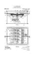
- Figure l is a sectional side elevation of a controller embcdyingmy improvements
- Fig. 2 is a bottom view thereof
- Fig. 3 is a sectional view taken on the lines 3 3 of Fig. 1
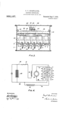
- Fig. 4 is a diagrammatic representation of the circuits.
- a frame or casing l supports a cross piece 2, of insulating material, which carries metal conductors in the form of shoes 3, 4, 5, G, and 7.
- sockets 3f, 4', 5, and 6 ofthe respective shoes 3, 4, 5, and 6 are carbon blocks 8, 9, 10fand 11 which are supported and pressed upward by arms 13, 14, 15 and 1G.
- These arms are pivoted to the respective shoes by pintles 18, 19, 2O and 21 and pressed up by coiled springs 23, 24, 25 and 2G each having terminals engaging the corresponding arm and shoe.
- Conductors 28, 29, 30 and 31 are fixed to respectiveshoes and the cai-bons to secure their electrical connection.
- the respective shoes are provided with sockets, as 3, 4, 5, 6, and 7 for connecting .a conductor therewith.
- the frame or casing supports guides 33 for controlling 4the movements of an insulating sliding member 34 which is adapted for reciprocaticn transversely with respect to the part 2.
- Two sets of niet-al conducting brushes or fingers 36, 37, 38 and 39, and 40, 41, 42, 43, and are fined' to sliding member 34 and arranged in pairs so that the members of each pair are inclined inwardly and adapted to be brought alternately into contact with a corresponding shoe, the brushes moving transversely to the surfaces of the shoes upon which they iinpinge.
- the finger 35 is secured to the member 34 by the metal angle 45, the Fingers 38 and 39 are secured to the part 34 by the metal angle 46, and these parts are electrically connected by the conductor 47.
- the fingers 36 and 37 are secured to the part 34 and electrically connected by the metal angle 48.
- the lingers 40 and 41 are secured to the part 34 and electrically connected by the metal angle 49.
- the fingers 42, 43 and 44 are secured to the part 34 and electrically connected by the metal angle 50.
- The'two sets of carbon plates 51, 52, 5i and 54, and 55, 56, 57, and 58, having the forms of wedge frustums, are secured to the part 34 by inclined conducting plates 59 clamped on the inner parts of the respective brushes or fingers and wedge shaped insulating members secured to the part 34, a pair of such carbon plates being held in the plane of each of the carbon blocks held by the shoes.
- a rack 61 is secured to the part 34 and a roller 62 on an arm 63 engages therewith.
- the arm is adapted to rock on a hinge connection 64 of the frame 1 and is held down by a spring 65, the-latter having its terminals connected with the bearings 6G and G7 on the members 63 and 64.
- An operating rod G8 is fixed to the coinniutator having the body 34 and extends in opposite directions therefrom.
- a battery G9 is connected by the conductor 7l), through the switch 7l and the motor field 72, with the shoe or contact 4, electrically connected with the carbon contact 9', and by the conductor 73 with the shoe or contact 7.
- a conductor 74, containing ,the resistance 75, is tapped onto the conductor T3 and the shoe or contact 6 electrically connected with the carbon Contact 1l.
- the motor -armature 7G is connected by the conductor 77 with the shoe .or contact 3 electrically connected with the carbon contact 8, and by vthe conductor 78 with the shoe or cont-act 5 electrically connected with the carbon contact 10.
- the contacts 51', 52', 53' and 54 are moved into engagement with the contacts 8 9, 10 and 11, when current flows from the battery through the conductor 70, field 7 2, contacts 9, 52', 51 and 8, conductor 77, armature 76, conductor 78, contacts 10, 53', 54 and 11, conductor 74, resistance 75, and conductor 73, to the battery.
- the commutator is moved so that contacts 40, 41,. 42, 43 and 44 engage the contacts 3, 4, 5, 6, and 7, when current flows from the battery through the conductor 70,
- a reciprocating commutator comprising two sets of metal contacts adapted to engage alternately with said metal contacts- Mother named, said commutator having two sets of carbon contacts adapted to engage alternately with said carbon contacts rst named.
- a commutator having two electrically separated contact lingers and two electrically separated carbon contacts, each of said carbon contacts being electrically connected with one tof said contact ngers, in combination with a contact .piece with whichsaid fingers are adapted to en age alternately, and electrically connecte carbon contact with which said carbon conwith said contact piece a tacts first named are adapted to engage alternately.
- a fixed member carriedby said fixed member a set of metal contacts having sockets therein, and movable in said sockets a set of carbon contacts, in combination with a reciprocating commutator having two sets of electrically separated carbon contacts adapted to be moved alternately into engagement with said 7 5, carbon contacts first named, and'two sets of metal contacts electrically connected respectively with said second named sets of carbon contacts and adapted to be moved alternately into engagement with said metal contacts lirst named.
- a reciprocating part of insulating material a pair of carbons, means for engaging said carbons toY said reciprocating part, brushes fixed to said g5 reciprocating part and electrically connected with the respective Acarbons, a fixed part, a rack and a spring pressed engaging device connecting said reciprocating and fixed parts.
- a xed member fixed to said member a set of conducting shoes containing sockets, movable in said sockets a set of carbons electrically connected therewith, spring pressed devices engaging the respective carbons, a reciprocating member, two sets of electrically separated carbons fixed to said reciprocating member and adapted to make contact with said set of carbons first named, and two sets of conducting lingers fixed to said reciprocating member and respectively connected electrically with said sets of carbons fixed to said reciprocating member, said conducting lingers being adapted for making contact alternately with said shoes.
- a supporting member a metal contact supported by said member, a carbon contact electrically connected with said met-al contact and supported thereby, a second supporting memberl adapted to reciprocate relatively to said supporting member first named, a carbon contact fixed to said second supporting member and adapted to slide upon said first named ll-5 carbon contact, and fixedy to said second supporting member a metal' Contact adapted to impinge upon said first named metal contact, said second named metal contact moving transversely to the surface of said first named metal contact engaging therewith.
- a supporting member a metal contact supportedby said member, a carbon contact electrically connected with said metal contact, a second sup- 125 porting member adapted to reciprocate relatively to said supporting member iirstnarned,
Landscapes
- Footwear And Its Accessory, Manufacturing Method And Apparatuses (AREA)
Description
T. V. BUGKWAL'IER.
ELECTRIC CONTROLLER.
APPLICATION FILED JANwzo. 1909.
l Ptented Sept. 7, 1909.
'2 s HBBTs-SHEET 1. f5
Wl TNESSES: ma.
T. V. BUCKWALTER.
ELECTRIC CONTROLLER.
APPLICATION Hmm JAN. zo, 1'909.
Patented Sept. 7, 1909.
2 SHEETS-SHEET f? WITNESSES:
sm. www.
A TTORNE Y.
TRACY V. BUGKWALTER, 0F ALTOONA, PENNSYLVANI.
ELECTRIC CONTROLLER.
Specification of Lette1's-Patent.
Patented Sept. '7, 1969.
Application filed January 20, 1909. Serial No. 473,227.
To all 'whom it may concer/n:
Be it known that I, TRACY V. BUCKWAL- TER, a citizen of the United States, residin in the city of Altoona, county of Blair, an State of Pennsylvania, have invented Improveniente in Electric Controllers.
My invention is an electric controller, of the reciprocating type, adapted to be operated from opposite ends of a motor car, vehicle or truck, to effect movement in opposite directions. Its leading object is to provide a simple, inexpensive and efficient controller, of the type specified, having therein means for obstructing high discharges on starting, preventing sparking and protecting the apparatus from shock or injury in throwing on the current.
The characteristic features of my improvements are fully disclosed in the accompanying drawings and the following description thereof.
In the drawings, Figure l is a sectional side elevation of a controller embcdyingmy improvements; Fig. 2 is a bottom view thereof; Fig. 3 is a sectional view taken on the lines 3 3 of Fig. 1; and Fig. 4 is a diagrammatic representation of the circuits.
In the embodiment of the improvements represented in the drawings, a frame or casing l supports a cross piece 2, of insulating material, which carries metal conductors in the form of shoes 3, 4, 5, G, and 7. In sockets 3f, 4', 5, and 6 ofthe respective shoes 3, 4, 5, and 6 are carbon blocks 8, 9, 10fand 11 which are supported and pressed upward by arms 13, 14, 15 and 1G. These arms are pivoted to the respective shoes by pintles 18, 19, 2O and 21 and pressed up by coiled springs 23, 24, 25 and 2G each having terminals engaging the corresponding arm and shoe. Conductors 28, 29, 30 and 31 are fixed to respectiveshoes and the cai-bons to secure their electrical connection. The respective shoes are provided with sockets, as 3, 4, 5, 6, and 7 for connecting .a conductor therewith.
The frame or casing supports guides 33 for controlling 4the movements of an insulating sliding member 34 which is adapted for reciprocaticn transversely with respect to the part 2. Two sets of niet-al conducting brushes or fingers 36, 37, 38 and 39, and 40, 41, 42, 43, and are fined' to sliding member 34 and arranged in pairs so that the members of each pair are inclined inwardly and adapted to be brought alternately into contact with a corresponding shoe, the brushes moving transversely to the surfaces of the shoes upon which they iinpinge. The finger 35 is secured to the member 34 by the metal angle 45, the Fingers 38 and 39 are secured to the part 34 by the metal angle 46, and these parts are electrically connected by the conductor 47. The fingers 36 and 37 are secured to the part 34 and electrically connected by the metal angle 48. The lingers 40 and 41 are secured to the part 34 and electrically connected by the metal angle 49. The fingers 42, 43 and 44 are secured to the part 34 and electrically connected by the metal angle 50.
The'two sets of carbon plates 51, 52, 5i and 54, and 55, 56, 57, and 58, having the forms of wedge frustums, are secured to the part 34 by inclined conducting plates 59 clamped on the inner parts of the respective brushes or fingers and wedge shaped insulating members secured to the part 34, a pair of such carbon plates being held in the plane of each of the carbon blocks held by the shoes.
A rack 61 is secured to the part 34 and a roller 62 on an arm 63 engages therewith. The arm is adapted to rock on a hinge connection 64 of the frame 1 and is held down by a spring 65, the-latter having its terminals connected with the bearings 6G and G7 on the members 63 and 64.
An operating rod G8 is fixed to the coinniutator having the body 34 and extends in opposite directions therefrom.
As shown in the diagrannnntic View represented in llig. 4, a battery G9 is connected by the conductor 7l), through the switch 7l and the motor field 72, with the shoe or contact 4, electrically connected with the carbon contact 9', and by the conductor 73 with the shoe or contact 7. A conductor 74, containing ,the resistance 75, is tapped onto the conductor T3 and the shoe or contact 6 electrically connected with the carbon Contact 1l. The motor -armature 7G is connected by the conductor 77 with the shoe .or contact 3 electrically connected with the carbon contact 8, and by vthe conductor 78 with the shoe or cont-act 5 electrically connected with the carbon contact 10. VVit-h the switch 71 closed, kwhen the connnntator is moved so that the carbon contacts 51, 52, 53 and 54 strike fthe respect-ive carbon contacts 8, 9, 10 and il, current .troni the buttery flows through conductor 70, field 72, contacts 9,
52, 53 and 10, conductor 78,armature 76,
conductor 77, contacts 8, 51 and 35, con-- ductor 47, contacts 33, 54,' 11 and 6, con ductcr 74, resistance 75 and conductor 73 `to the battery, producing the first speed. 1When the commutator is moved farther, so that the contacts 35, 36,' 37, 38 and 39 engage the respective contacts 3, 4, 5, 6, 'and 7, current from the battery flows through the conductcr 70, field 72, contacts 4, 36, 37 and 5, conductor 78, armature 76, conductor 77, contacts 3 Vand 35, conductor 47, contacts 38, 39 and 7, and conductor 73, cutting out the resistance and throwing inthe shunt circuit to produce the second speed.
To produce the first speed in the reverse direction the contacts 51', 52', 53' and 54 are moved into engagement with the contacts 8 9, 10 and 11, when current flows from the battery through the conductor 70, field 7 2, contacts 9, 52', 51 and 8, conductor 77, armature 76, conductor 78, contacts 10, 53', 54 and 11, conductor 74, resistance 75, and conductor 73, to the battery. To produce the second speed in the reverse direction, the commutator is moved so that contacts 40, 41,. 42, 43 and 44 engage the contacts 3, 4, 5, 6, and 7, when current flows from the battery through the conductor 70,
39 field 72, contacts 4, 41, 40 and 3, conductor 77, armature 76, conductor 78, contacts 5, 42, 43, 44 and 7 and conductor 73 to the battery. Theseveral contacts are thus so disposed that in moving the commutator to throw on the current, to operate the motor in each direction, the carbons first engage, in sliding contact, and thereafter the metal contacts engage, and in moving the commutator to throw oli the current the metal contacts iirst separate and thereafter'the carbons.
The operations of this mechanism are such that satisfactory engagements are obtained between the contacts, arcing is avoided and 45 injuries to the apparatusare obviated.
Having described my invention, I claim:
1. In an electric controller, a set of metal contacts, a set of carbon contacts electrically connected with said metal contacts, and
a reciprocating commutator comprising two sets of metal contacts adapted to engage alternately with said metal contacts- Erst named, said commutator having two sets of carbon contacts adapted to engage alternately with said carbon contacts rst named.
2. In an electric controller, a commutator having two electrically separated contact lingers and two electrically separated carbon contacts, each of said carbon contacts being electrically connected with one tof said contact ngers, in combination with a contact .piece with whichsaid fingers are adapted to en age alternately, and electrically connecte carbon contact with which said carbon conwith said contact piece a tacts first named are adapted to engage alternately.
3. In an electric controller, a fixed member, carriedby said fixed member a set of metal contacts having sockets therein, and movable in said sockets a set of carbon contacts, in combination with a reciprocating commutator having two sets of electrically separated carbon contacts adapted to be moved alternately into engagement with said 7 5, carbon contacts first named, and'two sets of metal contacts electrically connected respectively with said second named sets of carbon contacts and adapted to be moved alternately into engagement with said metal contacts lirst named.
4. In an electric controller, a reciprocating part of insulating material, a pair of carbons, means for engaging said carbons toY said reciprocating part, brushes fixed to said g5 reciprocating part and electrically connected with the respective Acarbons, a fixed part, a rack and a spring pressed engaging device connecting said reciprocating and fixed parts.
5. In an electric controller, a xed member, fixed to said member a set of conducting shoes containing sockets, movable in said sockets a set of carbons electrically connected therewith, spring pressed devices engaging the respective carbons, a reciprocating member, two sets of electrically separated carbons fixed to said reciprocating member and adapted to make contact with said set of carbons first named, and two sets of conducting lingers fixed to said reciprocating member and respectively connected electrically with said sets of carbons fixed to said reciprocating member, said conducting lingers being adapted for making contact alternately with said shoes.
6. In an electric controller, a supporting member, a metal contact supported by said member, a carbon contact electrically connected with said met-al contact and supported thereby, a second supporting memberl adapted to reciprocate relatively to said supporting member first named, a carbon contact fixed to said second supporting member and adapted to slide upon said first named ll-5 carbon contact, and fixedy to said second supporting member a metal' Contact adapted to impinge upon said first named metal contact, said second named metal contact moving transversely to the surface of said first named metal contact engaging therewith.
7. In an electric controller, a supporting member, a metal contact supportedby said member, a carbon contact electrically connected with said metal contact, a second sup- 125 porting member adapted to reciprocate relatively to said supporting member iirstnarned,
a carbon contact fixed. to said second supporting member andl adapted to slide upon said first named carbon contact without enico gagng said first named metal Contact, and n witness whereof I have herennto set fXed to Said second Supporting xnelnber a my nzune this 16th day of January, 1909., in 10 getal eonlet adzpted to nnpinge upon said the presence of the subscribing witnesses.
rst nznne Inetn Contact Without eno'avno said rst named carbon Contact, said eon' TRACY V' BUCKWLTER' nfnned metal Contact moving transversely to Ninessesr the surface of said rst named metal Contact Hom-:nr J .ums EARLEY, engaging therewith. Jos. G. DHNNY, Jr.
Priority Applications (1)
| Application Number | Priority Date | Filing Date | Title |
|---|---|---|---|
| US47322709A US933157A (en) | 1909-01-20 | 1909-01-20 | Electric controller. |
Applications Claiming Priority (1)
| Application Number | Priority Date | Filing Date | Title |
|---|---|---|---|
| US47322709A US933157A (en) | 1909-01-20 | 1909-01-20 | Electric controller. |
Publications (1)
| Publication Number | Publication Date |
|---|---|
| US933157A true US933157A (en) | 1909-09-07 |
Family
ID=3001580
Family Applications (1)
| Application Number | Title | Priority Date | Filing Date |
|---|---|---|---|
| US47322709A Expired - Lifetime US933157A (en) | 1909-01-20 | 1909-01-20 | Electric controller. |
Country Status (1)
| Country | Link |
|---|---|
| US (1) | US933157A (en) |
-
1909
- 1909-01-20 US US47322709A patent/US933157A/en not_active Expired - Lifetime
Similar Documents
| Publication | Publication Date | Title |
|---|---|---|
| US803486A (en) | Magnetically-operated switch. | |
| US801285A (en) | Electric controller. | |
| US568450A (en) | Electbio switch | |
| US603524A (en) | coachman | |
| US756711A (en) | Electric controller for alternating currents. | |
| US960450A (en) | Switch construction. | |
| US582772A (en) | Method of and apparatus for preventing formation of arcs when opening circuits | |
| US713712A (en) | Switch for electric circuits. | |
| US1005084A (en) | Electrical controller. | |
| US771989A (en) | Electric switch. | |
| US1473838A (en) | Lever arm for switches, rheostats, and like electric devices | |
| US523444A (en) | richardson | |
| US1178584A (en) | Circuit-controller. | |
| US1439561A (en) | Relay | |
| US746669A (en) | Current-regulator. | |
| US1268666A (en) | All-water rheostat. | |
| US1043532A (en) | Contact-switch equipment. | |
| US432561A (en) | Brush-reverser for electric motors | |
| US910478A (en) | Rheostat. | |
| US398663A (en) | Switch mechanism for electric railways | |
| US439602A (en) | S peters co | |
| US563575A (en) | Reversing-controller for electric motors | |
| US384116A (en) | Electric shunting device | |
| US1038151A (en) | Lamp-socket. | |
| US1582376A (en) | Switch for electric circuits |