US9329258B2 - Method for determining, in a fixed 3D frame of reference, the location of a moving craft, and associated computer program and device - Google Patents
Method for determining, in a fixed 3D frame of reference, the location of a moving craft, and associated computer program and device Download PDFInfo
- Publication number
- US9329258B2 US9329258B2 US14/443,845 US201314443845A US9329258B2 US 9329258 B2 US9329258 B2 US 9329258B2 US 201314443845 A US201314443845 A US 201314443845A US 9329258 B2 US9329258 B2 US 9329258B2
- Authority
- US
- United States
- Prior art keywords
- mobile machine
- characteristic points
- fixed frame
- axis
- determining
- Prior art date
- Legal status (The legal status is an assumption and is not a legal conclusion. Google has not performed a legal analysis and makes no representation as to the accuracy of the status listed.)
- Expired - Fee Related
Links
Images


Classifications
-
- G—PHYSICS
- G01—MEASURING; TESTING
- G01S—RADIO DIRECTION-FINDING; RADIO NAVIGATION; DETERMINING DISTANCE OR VELOCITY BY USE OF RADIO WAVES; LOCATING OR PRESENCE-DETECTING BY USE OF THE REFLECTION OR RERADIATION OF RADIO WAVES; ANALOGOUS ARRANGEMENTS USING OTHER WAVES
- G01S5/00—Position-fixing by co-ordinating two or more direction or position line determinations; Position-fixing by co-ordinating two or more distance determinations
- G01S5/16—Position-fixing by co-ordinating two or more direction or position line determinations; Position-fixing by co-ordinating two or more distance determinations using electromagnetic waves other than radio waves
- G01S5/163—Determination of attitude
-
- G—PHYSICS
- G05—CONTROLLING; REGULATING
- G05D—SYSTEMS FOR CONTROLLING OR REGULATING NON-ELECTRIC VARIABLES
- G05D1/00—Control of position, course, altitude or attitude of land, water, air or space vehicles, e.g. using automatic pilots
- G05D1/08—Control of attitude, i.e. control of roll, pitch, or yaw
- G05D1/0808—Control of attitude, i.e. control of roll, pitch, or yaw specially adapted for aircraft
-
- G—PHYSICS
- G05—CONTROLLING; REGULATING
- G05D—SYSTEMS FOR CONTROLLING OR REGULATING NON-ELECTRIC VARIABLES
- G05D1/00—Control of position, course, altitude or attitude of land, water, air or space vehicles, e.g. using automatic pilots
- G05D1/10—Simultaneous control of position or course in three dimensions
- G05D1/101—Simultaneous control of position or course in three dimensions specially adapted for aircraft
-
- G06K9/0063—
-
- G—PHYSICS
- G06—COMPUTING OR CALCULATING; COUNTING
- G06T—IMAGE DATA PROCESSING OR GENERATION, IN GENERAL
- G06T7/00—Image analysis
- G06T7/70—Determining position or orientation of objects or cameras
- G06T7/73—Determining position or orientation of objects or cameras using feature-based methods
-
- G—PHYSICS
- G06—COMPUTING OR CALCULATING; COUNTING
- G06T—IMAGE DATA PROCESSING OR GENERATION, IN GENERAL
- G06T2207/00—Indexing scheme for image analysis or image enhancement
- G06T2207/10—Image acquisition modality
- G06T2207/10016—Video; Image sequence
-
- G—PHYSICS
- G06—COMPUTING OR CALCULATING; COUNTING
- G06T—IMAGE DATA PROCESSING OR GENERATION, IN GENERAL
- G06T2207/00—Indexing scheme for image analysis or image enhancement
- G06T2207/10—Image acquisition modality
- G06T2207/10032—Satellite or aerial image; Remote sensing
-
- G—PHYSICS
- G06—COMPUTING OR CALCULATING; COUNTING
- G06T—IMAGE DATA PROCESSING OR GENERATION, IN GENERAL
- G06T2207/00—Indexing scheme for image analysis or image enhancement
- G06T2207/30—Subject of image; Context of image processing
- G06T2207/30244—Camera pose
Definitions
- the present invention relates to the field of the determination, in a 3D fixed frame of reference, of the location of a mobile machine provided with an image sensor associated with a first 3D local frame of reference, corresponding to the capture of an image, by said sensor, of the environment of the mobile machine comprising at least two characteristic points of said environment.
- flying machine such as drones for example, are used to accomplish tasks of exploration, recognition, monitoring etc. To achieve all of these tasks, such a flying machine must be capable of ascertaining its location, especially in order to carry out hovering flights.
- GPS Global Positioning System
- all the proposed approaches are based on filters, thus implying that initial location data must be provided. Now, an error in these initialization data can very significantly corrupt the estimated locations as a whole.
- a characteristic point is a point of the physical environment of the flying machine, which serves as frame in the images, and which is fixed (or else whose motion is known). Based on an image captured by the image sensor and comprising a characteristic point, the direction of this characteristic point is determined in a three-dimensional frame local to the flying machine.
- the present invention is aimed at proposing a solution which contributes to solving these drawbacks of the prior art.
- the Applicant has discovered, unexpectedly, that once the pitch and roll values corresponding to an image have been determined in an absolute frame of reference (i.e. one whose position is not dependent on the motion of the flying machine), it is possible to determine the position of the flying machine and the yaw value corresponding to this image, in the absolute frame of reference, and to do so without taking into account the initialization values of position or of yaw.
- an absolute frame of reference i.e. one whose position is not dependent on the motion of the flying machine
- the invention proposes a method of the aforementioned type characterized in that the angles of roll and of pitch of the mobile machine in the fixed frame of reference corresponding to said image capture having been determined in a previous step, the following steps are implemented, in relation to said captured image, so as to determine the angle of yaw and/or the coordinates of the mobile machine in the fixed frame of reference:
- a/ a second local frame of reference is defined in respect of the mobile machine comprising an axis exhibiting a known deviation of angle from the yaw axis of the fixed frame of reference, said second local frame of reference resulting from the succession of two rotations, one of said rotations about a first axis of the first local frame of reference being dependent on the angle of roll determined and the other of said rotations being dependent on the angle of pitch determined;
- c/ said coordinates of the two characteristic points in said second local frame of reference are thereafter expressed as a function of the distance between said characteristic points and of said determined values of quotients.
- the method according to the invention furthermore comprises one or more of the following characteristics:
- [ x 2 y 2 z 2 ] are the coordinates of the two characteristic points in the second local frame of reference;
- [ x 2 y 2 z 2 ] are the coordinates of the two characteristic points in the second local frame of reference;
- ⁇ ⁇ [ x 1 y 1 z 1 ] Rot ⁇ A - 1 ⁇ [ u 1 v 1 1 ] , where u 1 , v 1 are the coordinates of a pixel of the representation of one of the two characteristic points in the image;
- ⁇ . [ x 2 y 2 z 2 ] Rot . A - 1 . [ u 2 v 2 1 ] , where u 2 , v 2 are the coordinates of a pixel of the representation of the other of the two characteristic points in the image, A is a predetermined matrix of parameters intrinsic to the image sensor, ⁇ a factor of unknown value; and Rot is the matrix representing the succession of the two rotations;
- ⁇ ⁇ [ x 1 y 1 z 1 ] Rot ⁇ A - 1 ⁇ [ u 1 v 1 1 ] , where u 1 , v 1 are the coordinates of a pixel of the representation of one of the two characteristic points in the image;
- ⁇ ⁇ [ x 2 y 2 z 2 ] Rot ⁇ A - 1 ⁇ [ u 2 v 2 1 ] , where u 2 , v 2 are the coordinates of a pixel of the representation of the other of the two characteristic points in the image, A is a predetermined matrix of parameters intrinsic to the image sensor ( 7 ), ⁇ a factor of unknown value; and Rot is the matrix representing the succession of the two rotations.
- the present invention proposes a computer program for locating, in a 3D fixed frame of reference, a mobile machine provided with an image sensor associated with a first 3D local frame of reference corresponding to the capture of an image, by said sensor, of the environment of the mobile machine comprising at least two characteristic points of said environment, said program comprising instructions for implementing the steps of a method according to the first aspect of the invention during an execution of the program by processing means, the angles of roll and of pitch of the mobile machine in the fixed frame of reference corresponding to said image capture having been determined in a previous step.
- the present invention proposes a device for determining, in a 3D fixed frame of reference, the location of a mobile machine provided with an image sensor associated with a first 3D local frame of reference corresponding to the capture of an image, by said sensor, of the environment of the mobile machine comprising at least two characteristic points of said environment,
- said determining device being adapted for previously determining the angles of roll and of pitch of the mobile machine in the fixed frame of reference corresponding to said image capture;
- said determining device being characterized in that it is adapted for furthermore determining the angle of yaw and/or the coordinates of the mobile machine in the fixed frame of reference by defining a second local frame of reference in respect of the mobile machine comprising an axis exhibiting a known deviation of angle from the yaw axis of the fixed frame of reference, said second local frame of reference resulting from the succession of two rotations, one of said rotations about a first axis of the first local frame of reference being dependent on the angle of roll determined and the other of said rotations being dependent on the angle of pitch determined;
- the coordinates of each of the two characteristic points in said second local frame of reference being equal, to within an unknown common factor, to the result of the multiplication of a matrix defining said succession of rotations, by a matrix of intrinsic parameters of the image sensor and by the coordinates of a pixel corresponding to said characteristic point on the image, said determining device being adapted for determining the values taken by the quotients between said coordinates in such a way as to circumvent the unknown common factor;
- said determining device being adapted for thereafter expressing said coordinates of the two characteristic points in said second local frame of reference as a function of the distance between said characteristic points and of said determined values of quotients.
- FIG. 1 represents a flying machine
- FIG. 2 represents a processing device in an embodiment of the invention
- FIG. 3 is a flowchart of various steps implemented in an embodiment of the invention.
- FIG. 4 represents points in three-dimensional frames used in an embodiment of the invention
- FIG. 5 is a view of two characteristic points in a plane (X n , V n ) in an embodiment of the invention
- FIG. 6 is a flowchart of various steps implemented in an embodiment of the invention.
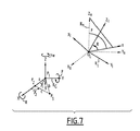
- FIG. 7 represents points in three-dimensional frames used in an embodiment of the invention.
- the location of a flying machine 10 is generally characterized on the one hand by the determination of the position, in space, of its center of gravity O, and on the other hand by its attitude, that is to say by its rotations, measured with the aid of angles of rotation, with respect to three axes defining a three-dimensional frame passing through an origin point of the frame, for example the center of gravity O: the angle of roll with respect to a roll axis A R , the angle of pitch with respect to a pitch axis A P and the angle of yaw with respect to a yaw axis A Y .
- the roll axis A R considered is the longitudinal axis of the flying machine 10
- the pitch axis A P is the transverse axis of the flying machine
- the yaw axis A Y is the axis perpendicular to the axes A R and A P .
- a flying machine 10 for example a drone, comprises a processing device 1 , with reference to FIG. 2 , adapted for performing measurements of inertial data and image captures and to process these data.
- This processing device 1 comprises a microprocessor 2 , a memory for storing data 3 , a set 4 of inertial sensors and an image sensor 7 .
- the set 4 of inertial sensors furthermore comprises a gyroscope module 6 comprising three mutually orthogonal gyroscopes, which provide, every period of length T B , measurements of rotation of the drone 10 about the axes (X I , Y I , Z I ).
- the image sensor 7 for example a monocular camera, is fixed on the drone 10 in such a way as to capture an image of the environment of the drone 10 every period of length T I .
- the captured images of the environment comprise especially a number N of characteristic points of the environment.
- the axis Z I is the optical axis of the image sensor 7 and the point O L is the optical center of the image sensor 7 .
- the coordinates of a point in space can be retrieved, to within a scale factor, as a function of the coordinates of the pixel representing this point in an image captured by the image sensor 7 , with the aid of a predetermined matrix A of parameters intrinsic to this image sensor and independent of the image.
- a characteristic point is for example an angle corner between two structures of the environment of the drone 10 , the center of a ball, the center of a laser spot etc.
- a program P of software instructions is stored, which, when it is executed by the microprocessor 2 , is adapted for implementing the steps indicated hereinbelow with reference to FIG. 3 .
- N is chosen at least equal to 2.
- P 1 and P 2 Two characteristic points considered are named P 1 and P 2 .
- a first step 100 with reference to FIGS. 3 and 4 , and given these two characteristic points P 1 , P 2 , an absolute reference frame R G is defined.
- the characteristic point P 1 is the origin of this reference frame R G , furthermore defined by three orthogonal axes X, Y and Z passing through P 1 and such that the axis Z is the axis parallel to the gravity vector g (such as determined by the accelerometer module 5 ) and of opposite direction, and the characteristic point P 2 is in the plane (X,Z), i.e. the characteristic point P 2 has a zero coordinate value on the axis Y.
- the determination of at least the 6 values defining, in the absolute reference frame R G , the position (x, y, z) of the point O L of the drone and the angles of roll R (relative to the axis X), pitch P (relative to the axis Y), yaw YW (relative to the axis Z) of the drone 10 , is carried out in steps 101 and 102 .
- step 101 these “absolute” values of roll R and of pitch P are determined, with respect to the roll axis taken equal to the axis X and to the pitch axis taken equal to the axis Y of the reference frame R G .
- step 102 Two characteristic points minimum are necessary in order to carry out step 102 , i.e. to determine the angle of yaw and the position with respect to the absolute frame R G .
- step 102 the yaw value YW and the position (x,y,z) of the drone 10 in the absolute frame R G are determined.
- the image considered comprises a representation of each characteristic point P 1 and P 2 , thereby making it possible to determine the position of these points (by means of a scale factor) in the local frame R I (cf. especially equations (1) and (2)).
- the axis Z n is defined in such a way that it has the same orientation as the axis Z of the general frame R G .
- the axis n represents the projection of the axis Z n on the plane (Y I , Z I ).
- the angle of pitch P is the angle between the axis Z n and the axis n
- the angle of roll R is the angle between the axis n and the axis Z I .
- the aim is to determine the coordinates
- ⁇ ⁇ [ x 1 y 1 z 1 ] Rot ⁇ A - 1 ⁇ [ u 1 v 1 1 ] , where u 1 , v 1 are the coordinates of the pixel on which the representation of the point P 1 in the image is centered; and
- ⁇ ⁇ [ x 2 y 2 z 2 ] Rot ⁇ A - 1 ⁇ [ u 2 v 2 1 ] , where u 2 , v 2 are the coordinates of the pixel on which the representation of the point P 2 in the image is centered; and
- ⁇ is the angle of rotation performed about the axis Z I corresponding to the yaw and fixed at 0
- ⁇ is the angle of rotation performed about the axis Y I and corresponding to the pitch
- ⁇ is the angle of rotation performed about the axis X I corresponding to the roll, to transform the frame R I into the frame R n .
- a step 102 _ 2 the value of z is determined.
- z is expressed as a function of D, to within the sign.
- the sign of z is determined thereafter. Indeed, the sign of the coordinate on the axis Z I of the characteristic points P 1 , P 2 is positive (otherwise they would not be on the image). From this we deduce the sign of the coordinate ( ⁇ z) of the characteristic points P 1 , P 2 on the axis Z n or Z (the matrix Rot depending on the values, known, of roll and pitch).
- a step 102 _ 3 we deduce therefrom the value of the yaw YW in the absolute frame R G with the aid of the arctan 2 function:
- a step 102 _ 22 which is implemented when the characteristic points do not both belong to the same plane (X,Y), i.e. have the same coordinate on the axis Z of the general frame R G , the coordinates of P 1 and P 2 are expressed in the following manner this time with a view to determining the value of the coordinate z of the point O L on the axis X:
- z is expressed as a function of D, to within the sign.
- y 2 - z ⁇ ( - 1 + ⁇ ⁇ ⁇ z D ) ⁇ v 2 .
- step 102 _ 3 is implemented as in case 1 and the value of the yaw YW in the absolute frame R G is deduced with the aid of the arctan 2 function:
- a step 103 optional, once the position of the drone and the angles of pitch, roll and yaw have been determined in the absolute frame R G , processings and/or actions are carried out as a function of these elements.
- the value of D can be estimated, for example by integrating data of images provided by the image sensor 7 and as a function of the inertial data provided by the accelerometer module 5 and the gyroscope module 6 and obtained when the drone moves with a non-zero acceleration, before switching to hovering flight (cf. especially the document mentioned above A. Martinelli, Vision and IMU Data Fusion: Closed-Form Solutions for Attitude, Speed, Absolute Scale and Bias Determination, Transaction on Robotics, Volume 28 (2012), Issue 1 (February), pp. 44-60).
- An error in the estimations of the roll and pitch values performed in step 101 affects in a linear manner the estimations of the position and of the yaw such as were described hereinabove with reference to step 102 .
- step 102 is replaced with a step 102 b is, in which three characteristic points P 1 , P 2 and P 3 at least appearing on the image considered and forming part of the plane (X,Y) are taken into account, instead of the two characteristic points P 1 , P 2 considered in step 102 .
- the three characteristic points P 1 , P 2 and P 3 are represented. These points P 1 , P 2 and P 3 are coplanar, in the plane (X,Y) of the frame R G . They form a triangle.
- step 102 b these operations described hereinabove in step 102 are implemented in relation to the frames of reference R G , R n , R I , by considering firstly the two points P 1 , P 2 , both in the plane (X,Y), secondly by considering the two points P 1 , P 3 , both in the plane (X,Y), and thirdly by considering the two points P 2 , P 3 , both in the plane (X,Y), as detailed hereinbelow
- YW 23 ⁇ arctan 2( y 3 ⁇ y 2 ,x 3 ⁇ x 2 ).
- angles ⁇ 1 and ⁇ 2 are known, for example
- cost This can be taken into account by defining a cost function, named cost, and by then seeking to minimize the cost function, for example with the aid of the Levenberg-Marquardt procedure.
- the cost function is defined with the aid of a non-linear least squares procedure.
- the Kalman filter does not update the state ⁇ , or the covariance matrix, since the angles ⁇ 1 and ⁇ 2 are constant over time.
- the roll and pitch values estimated in step 101 are used. Knowing the estimated roll and pitch values, a rotation of the local frame R I into the new local frame R n can be carried out, with an error due to the estimation of these angles of roll and pitch, with the aid of the matrix Rot.
- the local frame considered is that of the image sensor 7 .
- Other local frames may be selected, equation (1) giving the correspondence between the coordinates of a pixel in an image and the coordinates in the local frame which then have to be adapted accordingly in a known manner (cf. http://opencv.willowgarage.com/documentation/camera_calibration_and_3d_reconstruction.html)
- the invention has been described with reference to a drone hereinabove, but it can of course be implemented for any type of machine, especially flying machine, whose location must be determined.
- step 101 can be implemented in diverse ways.
- the step of estimating the values of roll R and pitch P amounts here to estimating the gravity in the local frame R I .
- Two cases are distinguished: a case where the inertial acceleration is negligible with respect to the gravitational acceleration, and a case where the inertial acceleration is not negligible with respect to the gravitational acceleration.
- the components employed for the vector G are those provided directly by the accelerometer module 5 . They are furthermore optionally filtered with the aid of an extended Kalman filter (EKF).
- EKF extended Kalman filter
- the estimated gravity vector undergoes a rotation by using the data of the gyroscope module 6 , and then an observation phase is implemented by using the acceleration provided by the accelerometer module 5 , which coincides with gravity since the inertial acceleration is assumed negligible.
- step 100 we consider the absolute frame R G defined hereinabove in step 100 (it will be noted, however, that any frame (x, y, z) whose z axis points vertically upwards (i.e. is parallel, and is opposite, to the gravity vector) can be considered for determining the values of roll and pitch in the mode of implementation described here of step 101 ).
- the vector W t ( ⁇ ) whose coordinates vary as a function of time represented by the variable ⁇ is, in the local frame in its state considered at an instant t, the vector of absolute coordinates w( ⁇ ).
- C t 1 t 2 the matrix which characterizes the rotation, occurring in the time interval [t 1 , t 2 ], of the local frame R I .
- the set of inertial sensors 4 provides acceleration data, i.e. the acceleration vector A, and data regarding the angular speed of the drone 10 .
- the accelerometer module 5 measures not only the inertial acceleration, i.e. the vector A inertial , but also the gravitational acceleration, i.e. the vector G.
- the images of the image sensor 7 comprise the representations of a characteristic point, for example P 1 , or of several characteristic points during the interval [T in , T end ] as represented in FIG. 4 .
- r ⁇ ( t ) r ⁇ ( T in ) + v ⁇ ( T in ) ⁇ ⁇ ⁇ ⁇ t + ⁇ t T in ⁇ ⁇ ⁇ T in ⁇ a ⁇ ( ⁇ ) ⁇ d ⁇ ⁇ ⁇ ⁇ d ⁇ ⁇ ( 10 )
- the accelerometer module 5 does not provide the acceleration vector a( ⁇ ), but it provides the acceleration in the local frame which also comprises the gravitational acceleration component. More particularly, the accelerometer module 5 provides A ⁇ ( ⁇ ) ⁇ A ⁇ inertial ( ⁇ ) ⁇ G ⁇ . It will be noted that the gravity is deducted since, when the drone 10 is not accelerating (i.e. A ⁇ inertia1 ( ⁇ ) is zero), the accelerometer module 5 detects an acceleration which is that of an object accelerated upwards in the absence of gravity. It will also be noted that the vector G ⁇ depends on the time only because the local frame can rotate.
- Equation (10) is rewritten with the aid of the vector A ⁇ ( ⁇ ) provided by the accelerometer module 5 :
- r ⁇ ( t ) r ⁇ ( T in ) + v ⁇ ( T in ) ⁇ ⁇ ⁇ ⁇ t + g ⁇ ⁇ ⁇ ⁇ t 2 2 + C T in ⁇ S T in ⁇ ( t ) ,
- the matrix C T in ⁇ can be obtained as a function of the angular speed of the drone 10 , during the interval [T in , ⁇ ], such as provided by the gyroscope module 6 (cf. J. A. Farrell, “Aided Navigation: GPS and High Rate Sensors”, McGraw-Hill, 2008).
- the vector S T in (t) can be obtained by integration of the data provided by the gyroscope module 6 and the accelerometer module 5 during the interval [T in , t].
- a single image captured at the time t provides all the vectors P i t (t) to within a scale factor.
- P T in i ⁇ ( t ) P T in i ⁇ ( T in ) - V T in ⁇ ( T in ) ⁇ ⁇ ⁇ ⁇ t - G T in ⁇ ⁇ ⁇ ⁇ t 2 2 - S T in ⁇ ( t ) ( 12 )
- the unit vector which has the same direction as P i j is called ⁇ i j .
- This system of linear equations (13) consists of 3(n i ⁇ 1)N equations in N ⁇ n i +6 unknowns.
- T j ⁇ - t j 2 2 ⁇ I 3 , S i ⁇ -t i I 3 and I 3 is the identity matrix of dimensions 3 ⁇ 3; 0 33 is the zero matrix of dimensions 3 ⁇ 3 (it is noted that the third set of columns disappears in case of absence of error).
- the gravity in the absolute frame R G is also determined since its components are the first three entries of X.
Landscapes
- Engineering & Computer Science (AREA)
- Physics & Mathematics (AREA)
- General Physics & Mathematics (AREA)
- Radar, Positioning & Navigation (AREA)
- Remote Sensing (AREA)
- Electromagnetism (AREA)
- Aviation & Aerospace Engineering (AREA)
- Automation & Control Theory (AREA)
- Theoretical Computer Science (AREA)
- Computer Vision & Pattern Recognition (AREA)
- Length Measuring Devices By Optical Means (AREA)
- Navigation (AREA)
- Image Analysis (AREA)
- Control Of Position, Course, Altitude, Or Attitude Of Moving Bodies (AREA)
Abstract
Description
-
- the coordinates, in the second local frame of reference, of the vector joining the two characteristic points are calculated, and according to which the angle of yaw of the mobile machine in the fixed frame of reference corresponding to said captured image is determined as a function of the arctan function applied to a variable dependent on said coordinates, in the local frame, of the vector joining the two characteristic points;
- the coordinates of the mobile machine are calculated in the fixed frame of reference corresponding to said captured image, as a function of coordinates of at least one of said characteristic points and of said angle of yaw determined in the fixed frame of reference;
- being given three characteristic points in the plane perpendicular to the yaw axis of the fixed frame of reference, the following steps are implemented in relation to said captured image:
- for each of the three pairs of characteristic points, steps b/ and c/ are implemented and three values of angles of yaw are thus determined as a function of the roll and pitch values determined in the previous step;
- on the basis of the three determined values of angles of yaw, a procedure for minimizing a function cos t(ξ)=(YW13−YW12−γ1)2+(YW23−YW12−γ2)2 is implemented in which the variables YW13, YW12 and YW23 are non-linear functions of ξ=└Roll, Pitch┘T where γ1 and γ2 represent two internal angles of the triangle of vertices of said characteristic points;
- as a function of the roll and pitch values arising from this minimization procedure, steps b/ and c/ are implemented in relation to two of the characteristic points, and thus an angle of yaw in the fixed frame of reference is determined;
- the method comprises a step of determining the angles γ1 and γ2, according to which we calculate:
and
where
are the coordinates of the characteristic point Pi in the second local frame of reference, i=1 to 3, being determined on the basis of the following equalities:
where ui, vi are the coordinates of a pixel of the representation of the characteristic point Pi in the image, A is a predetermined matrix of parameters intrinsic to the image sensor, λ·a factor of unknown value; and Rot is the matrix representing the succession of the two rotations;
-
- said step of determining the angles γ1 and γ2 is implemented in a Kalman filter procedure observation phase;
- the fixed frame of reference is defined such that the first characteristic point is the origin thereof, that the yaw axis is of direction contrary to the gravity vector and that the second characteristic point is of coordinate equal to zero on the pitch axis of the fixed frame of reference;
- an axis of the second local frame of reference is chosen parallel to the yaw axis of the fixed frame of reference;
- when the two characteristic points have one and the same coordinate value on the yaw axis of the fixed frame of reference, the coordinate value z of the location of the mobile machine on the yaw axis of the fixed frame of reference is:
with Δμ=μ1−μ2; Δμ=ν1−ν2 and D the distance between the two characteristic points,
and
where
and
are the coordinates of the two characteristic points in the second local frame of reference;
-
- when the two characteristic points do not have one and the same coordinate value on the yaw axis of the fixed frame of reference, the coordinate value z of the location of the mobile machine on the yaw axis of the fixed frame of reference is a solution of:
with Δμ=μ1−μ2; Δμ=ν1−ν2 and D the distance between the two characteristic points,
and
where
and
are the coordinates of the two characteristic points in the second local frame of reference;
-
- the method comprises a step of determining the angle of yaw YW of the mobile machine in the fixed frame of reference with the aid of the following formula:
-
- the method comprises at least one of steps i/ and ii/ hereinbelow, with
-
- i/ a step of determining the coordinate x of the location of the mobile machine on the roll axis of the second fixed frame of reference (Rn) by calculating x=cos θ·z·μ1+sin θ·z·ν1;
- ii/ a step of determining the coordinate y of the mobile machine on the pitch axis (Y) of the fixed frame of reference by calculating y=−sin θ·z·μ1+cos θ·z·ν1;
and
are calculated on the basis of the following equalities:
where u1, v1 are the coordinates of a pixel of the representation of one of the two characteristic points in the image;
where u2, v2 are the coordinates of a pixel of the representation of the other of the two characteristic points in the image, A is a predetermined matrix of parameters intrinsic to the image sensor, λ·a factor of unknown value; and Rot is the matrix representing the succession of the two rotations;
and
are calculated on the basis of the following equalities:
where u1, v1 are the coordinates of a pixel of the representation of one of the two characteristic points in the image;
where u2, v2 are the coordinates of a pixel of the representation of the other of the two characteristic points in the image, A is a predetermined matrix of parameters intrinsic to the image sensor (7), λ·a factor of unknown value; and Rot is the matrix representing the succession of the two rotations.
where λ is a positive proportionality factor, independent of the image.
proportional to
giving the direction of the point M from the origin OL of the frame RI:
of the point OL in the absolute frame RG, as well as the angle YW of the axis Xn with respect to the axis X (YW being the value of the angle of yaw in the absolute frame RG).
the coordinates of the characteristic point P1, and
those of the characteristic point P2, in the new local frame Rn.
and
where u1, v1 are the coordinates of the pixel on which the representation of the point P1 in the image is centered; and
where u2, v2 are the coordinates of the pixel on which the representation of the point P2 in the image is centered; and
and
we deduce therefrom the values of
and
of the point OL in the absolute frame RG, as well as the angle of yaw YW with respect to the axis Z of this frame RG.
and
and calling D the distance separating P1 from P2, it follows that
Δμ=μ1−μ2;Δν=ν1−ν2.
x=−cos θ·x 1−sin θ·y 1 (5)
y=sin θ·x 1−cos θ·y 1 (6)
of OL representing the position of the drone in the absolute frame RG are thus determined, as is also the angle of yaw YW sought with respect to this absolute frame.
and
and D being the distance separating P1 from P2 and
Δμ=μ1−μ2;Δν=ν1−ν2, we obtain the second-order polynomial equation in z:
is known, the above equation can be used to determine
and
x=−cos θ·x 1−sin θ·y 1 (5)
y=sin θ·x 1−cos θ·y 1 (6)
of OL representing the position of the drone in the absolute frame RG are thus determined, as is also the angle of yaw with respect to this absolute frame.
be the coordinates of the characteristic point Pi, i=1 to 3, in the new local frame Rn and
YW 12=−arctan 2(γ2 −y 1 ,x 2 −x 1)
calling D the distance separating P1 from P2.
YW 13=−arctan 2(y 3 −y 1 ,x 3 −x 1).
YW 23=−arctan 2(y 3 −y 2 ,x 3 −x 2).
YW 13 =YW 12+γ1
YW 23 =YW 12+γ2.
γ1 =YW 13 −YW 12
γ2 =YW 23 −YW 12.
and
the sought-after estimation of the angle of yaw, i.e. YW=YW12, can be corrected, taking this constraint into account.
cos t(ξ)=(YW 13 −YW 12−γ1)2+(YW 23 −YW 12−γ2)2,
in which the variables YWij are non-linear functions of ξ=Roll,Pitch]T].
and
and for the initial covariance matrix Ptri (for example, the initial value for Ptri is
with the value σpt being equal to the uncertainty in radians in the knowledge of the angle values γ1 and γ2.
of the characteristic points Pi, i=1 to 3 in the new local frame Rn, are such that:
a=z√{square root over ((μ2−μ1)2+(ν2−ν1)2)}{square root over ((μ2−μ1)2+(ν2−ν1)2)}
b=z√{square root over ((μ3−μ1)2+(ν3−ν1)2)}{square root over ((μ3−μ1)2+(ν3−ν1)2)}
c=z√{square root over ((μ3−μ2)2+(ν3−ν2)2)}{square root over ((μ3−μ2)2+(ν3−ν2)2)}
c 2 =a 2 +b 22ab cos γ1
and
b 2 =a 2 +c 22ac cos(π−γ2).
in the frame RI,
and R=arctan 2(Gy,Gz) if cos P<0 and R=arctan 2(Gy,Gz)+π if cos P>0.
P i j ≡P i T
P i ≡P i T
V≡V T
G≡G T
S j ≡S T
P i −Vt j −Gt j 2/2−λi j·μi j =S j (12)
Gt j 2/2−Vt j+μ1 1·μ1 1−λj 1·μj 1 =S j
λ1 1·μ1 1−λj 1·μj 1−λ1 i·μ1 i+λj i·μj i=03
Si≡-tiI3 and I3 is the identity matrix of
φX=S (14).
|πX| 2 =g 2. (15).
Claims (19)
a=√{square root over ((μ2−μ1)2+(ν2−ν1)2)}{square root over ((μ2−μ1)2+(ν2−ν1)2)} b=√{square root over ((μ3−μ1)2+(ν3−ν1)2)}{square root over ((μ3−μ1)2+(ν3−ν1)2)} c=√{square root over ((μ3−μ2)2+(ν3−ν2)2)}{square root over ((μ3−μ2)2+(ν3−ν2)2)},
Applications Claiming Priority (3)
| Application Number | Priority Date | Filing Date | Title |
|---|---|---|---|
| FR1260963A FR2998363B1 (en) | 2012-11-19 | 2012-11-19 | METHOD FOR DETERMINING, IN A 3D FIXED REFERENTIAL, THE LOCATION OF A MOVING GEAR, ASSOCIATED DEVICE AND COMPUTER PROGRAM |
| FR1260963 | 2012-11-19 | ||
| PCT/EP2013/074149 WO2014076294A1 (en) | 2012-11-19 | 2013-11-19 | Method for determining, in a fixed 3d frame of reference, the location of a moving craft, and associated computer program and device |
Publications (2)
| Publication Number | Publication Date |
|---|---|
| US20150293207A1 US20150293207A1 (en) | 2015-10-15 |
| US9329258B2 true US9329258B2 (en) | 2016-05-03 |
Family
ID=48224853
Family Applications (1)
| Application Number | Title | Priority Date | Filing Date |
|---|---|---|---|
| US14/443,845 Expired - Fee Related US9329258B2 (en) | 2012-11-19 | 2013-11-19 | Method for determining, in a fixed 3D frame of reference, the location of a moving craft, and associated computer program and device |
Country Status (3)
| Country | Link |
|---|---|
| US (1) | US9329258B2 (en) |
| FR (1) | FR2998363B1 (en) |
| WO (1) | WO2014076294A1 (en) |
Families Citing this family (16)
| Publication number | Priority date | Publication date | Assignee | Title |
|---|---|---|---|---|
| CN104482924B (en) * | 2014-12-11 | 2016-11-09 | 中国航天空气动力技术研究院 | Visual measurement method of object pose and orientation |
| US9986150B2 (en) * | 2015-09-30 | 2018-05-29 | Ricoh Co., Ltd. | Algorithm to estimate yaw errors in camera pose |
| US10104282B2 (en) | 2015-09-30 | 2018-10-16 | Ricoh Co., Ltd. | Yaw user interface |
| US10073531B2 (en) | 2015-10-07 | 2018-09-11 | Google Llc | Electronic device pose identification based on imagery and non-image sensor data |
| CN105573341B (en) * | 2016-01-22 | 2018-08-10 | 深圳泰山体育科技股份有限公司 | A kind of aircraft optical control method and system |
| CN109029495B (en) * | 2017-06-09 | 2020-11-20 | 苏州触达信息技术有限公司 | A reverse calibrator, reverse calibration system and method for calibrating point coordinates |
| CN106569222A (en) * | 2016-11-01 | 2017-04-19 | 湖北航天技术研究院总体设计所 | Azimuth measurement method based on distance measurement principle |
| CN107607933B (en) * | 2017-08-24 | 2019-07-26 | 中国电子科技集团公司第五十四研究所 | A high-precision positioning method for long-range UAV based on pitch angle iteration |
| US10784841B2 (en) * | 2018-03-08 | 2020-09-22 | Cnh Industrial America Llc | Kalman filter for an autonomous work vehicle system |
| CN108761468A (en) * | 2018-06-13 | 2018-11-06 | 董昊旻 | mapping method and device |
| CN109379564A (en) * | 2018-10-30 | 2019-02-22 | 长春市万易科技有限公司 | A kind of gas pipeline unmanned plane inspection device and method for inspecting |
| CN109491402B (en) * | 2018-11-01 | 2020-10-16 | 中国科学技术大学 | Multi-unmanned aerial vehicle cooperative target monitoring control method based on cluster control |
| CN109782786B (en) * | 2019-02-12 | 2021-09-28 | 上海戴世智能科技有限公司 | Positioning method based on image processing and unmanned aerial vehicle |
| CN110411443B (en) * | 2019-06-05 | 2023-05-02 | 西京学院 | A coal shearer rocker arm inertial/visual combined attitude determination device and method |
| CN115900655B (en) * | 2022-11-04 | 2026-04-28 | 南京韦博智控科技有限公司 | A method for planning inspection routes |
| CN119648810B (en) * | 2024-11-11 | 2025-10-28 | 中国科学院沈阳自动化研究所 | A method for grasping and positioning unmanned aerial vehicles on a mobile offshore platform |
Citations (7)
| Publication number | Priority date | Publication date | Assignee | Title |
|---|---|---|---|---|
| US20080195316A1 (en) | 2007-02-12 | 2008-08-14 | Honeywell International Inc. | System and method for motion estimation using vision sensors |
| EP2144038A2 (en) | 2008-07-10 | 2010-01-13 | Lockheed Martin Corporation | Inertial measurement using an imaging sensor and a digitized map |
| EP2372656A2 (en) | 2010-03-04 | 2011-10-05 | Honeywell International Inc. | Method and apparatus for vision aided navigation using image registration |
| US20120232718A1 (en) * | 2011-03-08 | 2012-09-13 | Parrot | Method of piloting a multiple rotor rotary-wing drone to follow a curvilinear turn |
| US20120308084A1 (en) * | 2009-11-19 | 2012-12-06 | Astrium Sas | Method for estimating the movement of a traveling observation instrument flying over a celestial body |
| US8902308B2 (en) * | 2010-08-25 | 2014-12-02 | Lakeside Labs Gmbh | Apparatus and method for generating an overview image of a plurality of images using a reference plane |
| US9074892B2 (en) * | 2013-03-15 | 2015-07-07 | Ian Michael Fink | System and method of determining a position of a remote object |
-
2012
- 2012-11-19 FR FR1260963A patent/FR2998363B1/en not_active Expired - Fee Related
-
2013
- 2013-11-19 WO PCT/EP2013/074149 patent/WO2014076294A1/en not_active Ceased
- 2013-11-19 US US14/443,845 patent/US9329258B2/en not_active Expired - Fee Related
Patent Citations (7)
| Publication number | Priority date | Publication date | Assignee | Title |
|---|---|---|---|---|
| US20080195316A1 (en) | 2007-02-12 | 2008-08-14 | Honeywell International Inc. | System and method for motion estimation using vision sensors |
| EP2144038A2 (en) | 2008-07-10 | 2010-01-13 | Lockheed Martin Corporation | Inertial measurement using an imaging sensor and a digitized map |
| US20120308084A1 (en) * | 2009-11-19 | 2012-12-06 | Astrium Sas | Method for estimating the movement of a traveling observation instrument flying over a celestial body |
| EP2372656A2 (en) | 2010-03-04 | 2011-10-05 | Honeywell International Inc. | Method and apparatus for vision aided navigation using image registration |
| US8902308B2 (en) * | 2010-08-25 | 2014-12-02 | Lakeside Labs Gmbh | Apparatus and method for generating an overview image of a plurality of images using a reference plane |
| US20120232718A1 (en) * | 2011-03-08 | 2012-09-13 | Parrot | Method of piloting a multiple rotor rotary-wing drone to follow a curvilinear turn |
| US9074892B2 (en) * | 2013-03-15 | 2015-07-07 | Ian Michael Fink | System and method of determining a position of a remote object |
Non-Patent Citations (3)
| Title |
|---|
| Beall, Chris, et al., Attitude Heading Reference System with Rotation-Aiding Visual Landmarks, 15th International Conference on Information Fusion, IEEE, pp. 976-982, Jul. 2012. |
| Martinelli, Agostino, Vision and IMU Data Fusion: Closed-Form Solutions for Attitude, Speed, Absolute Scale, and Bias Determination, IEEE Transactions on Robotics, vol. 28 No. 1, pp. 44-60, Feb. 2012. |
| Weiss, Stephan, Vision Based Navigation for Micro Helicopters, pp. 1-205, Jan. 2012. |
Also Published As
| Publication number | Publication date |
|---|---|
| US20150293207A1 (en) | 2015-10-15 |
| FR2998363B1 (en) | 2015-01-02 |
| FR2998363A1 (en) | 2014-05-23 |
| WO2014076294A1 (en) | 2014-05-22 |
Similar Documents
| Publication | Publication Date | Title |
|---|---|---|
| US9329258B2 (en) | Method for determining, in a fixed 3D frame of reference, the location of a moving craft, and associated computer program and device | |
| US20250130045A1 (en) | Square-Root Multi-State Constraint Kalman Filter for Vision-Aided Inertial Navigation System | |
| US11650334B2 (en) | Acceleration of real time computer vision processing on UAVs through GPS attitude estimation | |
| Weiss et al. | Monocular vision for long‐term micro aerial vehicle state estimation: A compendium | |
| Weiss et al. | Real-time metric state estimation for modular vision-inertial systems | |
| US9243916B2 (en) | Observability-constrained vision-aided inertial navigation | |
| Lupton et al. | Visual-inertial-aided navigation for high-dynamic motion in built environments without initial conditions | |
| US8761439B1 (en) | Method and apparatus for generating three-dimensional pose using monocular visual sensor and inertial measurement unit | |
| Guo et al. | IMU-RGBD camera 3D pose estimation and extrinsic calibration: Observability analysis and consistency improvement | |
| EP2730888A1 (en) | Method to determine a direction and amplitude of a current velocity estimate of a moving device | |
| KR20200044420A (en) | Method and device to estimate position | |
| CN108036785A (en) | A kind of aircraft position and orientation estimation method based on direct method and inertial navigation fusion | |
| US20230366680A1 (en) | Initialization method, device, medium and electronic equipment of integrated navigation system | |
| Crocoll et al. | Model‐aided navigation for a quadrotor helicopter: A novel navigation system and first experimental results | |
| Zhang et al. | Vision-aided localization for ground robots | |
| CN108827288A (en) | A kind of dimensionality reduction strapdown inertial navigation system Initial Alignment Method and system based on dual quaterion | |
| CN109141411B (en) | Positioning method, positioning device, mobile robot, and storage medium | |
| CN119845247A (en) | Multi-sensor fusion SLAM method under dynamic scene | |
| CN115930959A (en) | Vision initialization method, device and flying car | |
| Johansen et al. | Globally exponentially stable Kalman filtering for SLAM with AHRS | |
| Hua et al. | Attitude, linear velocity and depth estimation of a camera observing a planar target using continuous homography and inertial data | |
| KR101564020B1 (en) | A method for attitude reference system of moving unit and an apparatus using the same | |
| US20240159539A1 (en) | Method for assisting with the navigation of a vehicle | |
| US11280617B2 (en) | High performance dual mode mixing inertial navigation system | |
| Koch et al. | Multi-sensor robust relative estimation framework for GPS-denied multirotor aircraft |
Legal Events
| Date | Code | Title | Description |
|---|---|---|---|
| AS | Assignment |
Owner name: INRIA INSTITUT NATIONAL DE RECHERCHE EN INFORMATIQ Free format text: ASSIGNMENT OF ASSIGNORS INTEREST;ASSIGNORS:ZANATI, STEFANO AL;TROIANI, CHIARA;MARTINELLI, AGOSTINO;SIGNING DATES FROM 20150608 TO 20150707;REEL/FRAME:037663/0860 |
|
| STCF | Information on status: patent grant |
Free format text: PATENTED CASE |
|
| FEPP | Fee payment procedure |
Free format text: PAYOR NUMBER ASSIGNED (ORIGINAL EVENT CODE: ASPN); ENTITY STATUS OF PATENT OWNER: SMALL ENTITY Free format text: PAYER NUMBER DE-ASSIGNED (ORIGINAL EVENT CODE: RMPN); ENTITY STATUS OF PATENT OWNER: SMALL ENTITY |
|
| MAFP | Maintenance fee payment |
Free format text: PAYMENT OF MAINTENANCE FEE, 4TH YR, SMALL ENTITY (ORIGINAL EVENT CODE: M2551); ENTITY STATUS OF PATENT OWNER: SMALL ENTITY Year of fee payment: 4 |
|
| FEPP | Fee payment procedure |
Free format text: MAINTENANCE FEE REMINDER MAILED (ORIGINAL EVENT CODE: REM.); ENTITY STATUS OF PATENT OWNER: SMALL ENTITY |
|
| LAPS | Lapse for failure to pay maintenance fees |
Free format text: PATENT EXPIRED FOR FAILURE TO PAY MAINTENANCE FEES (ORIGINAL EVENT CODE: EXP.); ENTITY STATUS OF PATENT OWNER: SMALL ENTITY |
|
| STCH | Information on status: patent discontinuation |
Free format text: PATENT EXPIRED DUE TO NONPAYMENT OF MAINTENANCE FEES UNDER 37 CFR 1.362 |
|
| FP | Lapsed due to failure to pay maintenance fee |
Effective date: 20240503 |