US932771A - Apparatus for making sulfuric acid. - Google Patents
Apparatus for making sulfuric acid. Download PDFInfo
- Publication number
- US932771A US932771A US47018908A US1908470189A US932771A US 932771 A US932771 A US 932771A US 47018908 A US47018908 A US 47018908A US 1908470189 A US1908470189 A US 1908470189A US 932771 A US932771 A US 932771A
- Authority
- US
- United States
- Prior art keywords
- chamber
- lead
- sulfuric acid
- tower
- sheets
- Prior art date
- Legal status (The legal status is an assumption and is not a legal conclusion. Google has not performed a legal analysis and makes no representation as to the accuracy of the status listed.)
- Expired - Lifetime
Links
- QAOWNCQODCNURD-UHFFFAOYSA-N Sulfuric acid Chemical compound OS(O)(=O)=O QAOWNCQODCNURD-UHFFFAOYSA-N 0.000 title description 24
- IJGRMHOSHXDMSA-UHFFFAOYSA-N Atomic nitrogen Chemical compound N#N IJGRMHOSHXDMSA-UHFFFAOYSA-N 0.000 description 12
- 238000006243 chemical reaction Methods 0.000 description 12
- 239000007789 gas Substances 0.000 description 11
- 238000004519 manufacturing process Methods 0.000 description 8
- 229910052757 nitrogen Inorganic materials 0.000 description 6
- NINIDFKCEFEMDL-UHFFFAOYSA-N Sulfur Chemical compound [S] NINIDFKCEFEMDL-UHFFFAOYSA-N 0.000 description 5
- 239000002253 acid Substances 0.000 description 5
- 238000010276 construction Methods 0.000 description 5
- 229910052717 sulfur Inorganic materials 0.000 description 5
- 239000011593 sulfur Substances 0.000 description 5
- 238000001816 cooling Methods 0.000 description 4
- 238000000034 method Methods 0.000 description 3
- LSNNMFCWUKXFEE-UHFFFAOYSA-N Sulfurous acid Chemical compound OS(O)=O LSNNMFCWUKXFEE-UHFFFAOYSA-N 0.000 description 2
- 239000007795 chemical reaction product Substances 0.000 description 2
- 238000009432 framing Methods 0.000 description 2
- 235000000396 iron Nutrition 0.000 description 2
- 239000000463 material Substances 0.000 description 2
- 239000000203 mixture Substances 0.000 description 2
- VWDWKYIASSYTQR-UHFFFAOYSA-N sodium nitrate Chemical compound [Na+].[O-][N+]([O-])=O VWDWKYIASSYTQR-UHFFFAOYSA-N 0.000 description 2
- 210000001364 upper extremity Anatomy 0.000 description 2
- PEDCQBHIVMGVHV-UHFFFAOYSA-N Glycerine Chemical compound OCC(O)CO PEDCQBHIVMGVHV-UHFFFAOYSA-N 0.000 description 1
- 230000000694 effects Effects 0.000 description 1
- 210000003414 extremity Anatomy 0.000 description 1
- 239000011440 grout Substances 0.000 description 1
- 150000002500 ions Chemical class 0.000 description 1
- 229910052751 metal Inorganic materials 0.000 description 1
- 239000002184 metal Substances 0.000 description 1
- 239000000047 product Substances 0.000 description 1
- 235000010344 sodium nitrate Nutrition 0.000 description 1
- 239000004317 sodium nitrate Substances 0.000 description 1
Images
Classifications
-
- C—CHEMISTRY; METALLURGY
- C01—INORGANIC CHEMISTRY
- C01B—NON-METALLIC ELEMENTS; COMPOUNDS THEREOF; METALLOIDS OR COMPOUNDS THEREOF NOT COVERED BY SUBCLASS C01C
- C01B17/00—Sulfur; Compounds thereof
- C01B17/69—Sulfur trioxide; Sulfuric acid
- C01B17/74—Preparation
- C01B17/82—Preparation of sulfuric acid using a nitrogen oxide process
- C01B17/84—Chamber process
Definitions
- My invention relates to the chamber process of making sulfuric acid.
- the materials used are he following:--1.
- SO derived by burning sulfur, by roasting pyrites or from any other suitable source.
- ()xids of nitrogen which are usually obtained from sodium nitrate.
- the apparatus usually employed is, besides the source of the sulfur gases, :1 Glover tower into which the sulfur gases mixed with air are first intr **d, :1 series of loud chambers in which the gases are introduced after passing through the Qllover lower and in whicln nixed with nitrogen oxids and steam, the principal reaction itlllQS place;
- chamber taking ⁇ its supply of gas from the if more than one is employed are run parallel and not in series.
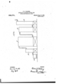
- F'gure 1 is a conventional view in side yalevation of a suliuric; 'aciid plant embodying in a single lend chamber, so that I secure in In the lead chambers as connnonly conill the plant additional chambers may be used ion Glover tower direct so that. all chambers the presentinyentian.
- Fig. 2&5 a view of a vertical transverse section through thelcad chamber forming a part of the sulfuric acid plant. and taken on the longest horizontal axis.
- Fig. 3 is also a vertical transverse sectional view at the lead chamber taken at rightangles to the plan of Fig. 2.
- Fig. 1 is a conventional view in side yalevation of a suliuric; 'aciid plant embodying in a single lend chamber, so that I secure in In the lead chambers as connnonly conill the plant additional chambers may be used ion Glover tower direct so that. all chambers the presentinyentian.
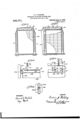
- Fig. 4 is adetail view showing the upper framing and means for connecting theuppcr or root'- ing lead sheets to the supporting truss work.
- Fig. 5 is a view-in detail of the means for supportinglhe rooting lead sheets taken at right anglcsto Fig.4.
- Fig. (3 is a detail view of a vertical section showing the means for attaching it 0 side sheets to the truss work.
- Fig. 1 of the drawings represents a plant embodying my improved lead chamber.
- A is the roaster which is represented as the source. of the S0 (unploycd.)
- B represents the Glover tower, through which the sulfur gases in their upward passage serve to separate. from the acid running in the opposite direction through same the nitrogen oxids absorbed in the Gay-Lussac tower which will be hereinafter referred to.
- C represents my improved. lead chamber which is shown in more detail in Figs. 2 to 6 inclusive showing the method by which the lead lining of the side and top of the tower is held in place, these means forming another novel fcaturc or the form of lead chamber I employ.
- Fig. 1 does not represent a complete producing plant in all of its totails and to be further understood that said lant is similar in all principles of operation with an up-twdate sulfuric acid producing plant-and that the novelty of the present invention resides in the leadchamber, both as to its form, proportions hnd manner of construction.
- the lead chum-- her shown at C in Fig.1 is in the form o tower, that is to say a. chamber whose vertical axis is greater than any horizontal axis preferably in the proportion as above stated of 3 to 2 although it. is to be understood that the invention is not limited to such exact proportions.
- the lead chamber is sup.- ported by any approved form of framing which as here shown and preferably employed is of tru construction having towers or'upright truss standards 10of any approved number and relating one to the other and jointed on their upper extremi ties by means of horizontal trusses 11 which may be of substantial usual roof truss construction.
- the roof trusses 11 are arranged at right angles to each other and of any approved mnnber to support the roofing lead sheets as hereinafter described. Extending along parallel with one axis of the chamber here show: as the longer axis are a plurality of commercial metal beams 12 shown at. Fig.
- the beams 12 are supported from the roof truss by any approved construction as the rods or hangers '13, such beams 12 being spaced apart. and disposed inparallelism. Between the beams 12 and disposed at right. angles thereto are a plurality of other beams 14' here shown also as composed of angle irons, although the particular forin of such beams is immaterial. The ends or extremities of the beams 14 rest upon the outwardly extending flanges of thebeams 12 and between the component. u'iembers of the beams 14. are secured hangers 15 in any approved manner as by the use of a washer 16 bearing upon the adiaeent'.
- the hangers '15 are provided at their lower ends with hooks or eyes 18 which embrace rods 1!) which said rods are iucased in rolls 20 which are formedalong the edges of lead stri s 21.
- the lead strips 21 have their lower edges bent at right. angles in'cased to form portions 22 which are secured to the top or roofing lead sheets 23. It; will be noted that strips 21 and their supporting hangers are spaced at, intervals along the lead sheets as shown at Figs. 2 and 3.
- the side lead sheets Q l are suspended at.
Landscapes
- Chemical & Material Sciences (AREA)
- Organic Chemistry (AREA)
- Inorganic Chemistry (AREA)
- Physical Or Chemical Processes And Apparatus (AREA)
- Organic Low-Molecular-Weight Compounds And Preparation Thereof (AREA)
Description
P. J. FALDING.
APPARATUS FOR MAKING SULFUBIO AOID.
APPLIOATIO! rmzn use. 31. 1m; 7
932,771. I Patented Aug. 31. 1909.
3 SHEETS-BEBE! 1.
WITNESSES INVENTOR A m an P. J. FALDING. APPARATUS FOR. MAKING SULFUBIG ACID.
APPLIOATIOH FILED DBO. 31, 190B.
Patent'd Afi 31. 1909.
0 TTO NEY mvimon' WTNESSESL 068M 1" Wk ff Y uremic J. rnnr'ua, or m max, n. 1'.
APPABATlIS FOR IAKING SULFUBIC ADID- Speclfleatmn a: Letters Patent. Patented Afig. 31, 1 909'.
Application filed December 81, 1908. Serial No. 70,189.
To all whom iL-m/zy concern:
Be it known that I, Fmzmzmc J. FALmNo, a citizen of the United States, residing at New Yor in the county oi New York and State of New-York, have invented certain. new and useful Improvement. in Apparatus for the Manufacture of Sulfuric Acid; and I do hereby declare the following to he a full, clear, and exact description of the invention, such as will enable, others skilled in the art to which it appertuins; to n'mlie and use the some.
My invention relates to the chamber process of making sulfuric acid. In the manutincture of acid by this method, the materials used are he following:--1. SO derived by burning sulfur, by roasting pyrites or from any other suitable source. 2. ()xids of nitrogen which are usually obtained from sodium nitrate. 3. \Vllltl' in the form f 5l(tllll. 4. Air, the nitrogen of which takes no part in the reactions involved and must be continuously remove-l.
'The apparatus usually employed is, besides the source of the sulfur gases, :1 Glover tower into which the sulfur gases mixed with air are first intr duced, :1 series of loud chambers in which the gases are introduced after passing through the Qllover lower and in whicln nixed with nitrogen oxids and steam, the principal reaction itlllQS place;
. and a GnyrLm-isne tower from which the gases make their final exit. A series of these lead chambers are generally employed,
the reaction in each being qualitatively the some but quantitatively different, the reaction in the lit-3i. clunnl'icr usually being much greater than in that of any succeeding chamber and the reaction in the last chamber the least. These lend ehiunbers are commonly made representing in tllell sections a longitudinal line; their individuiil length being from 50 to 9.00 feet with a width of from 10 to 40 feet and :1 heightvurying from 6 to' 40 feet. T he average cross section is from 20 to 30 feet wide and from 18 to 24 feet high. The relation of the width to the height has. generally been considered immaterial being more generally dictated by problems oi incclmnical construction rather tlnin by any rcfprcnce t0 the effect of their dimensions on (be working of the chambers in practical ope'rntkin. In fact it has generally bon recognized that a plurality of lead chambers has been necessary regardless of the individual dimensions of each lead chamber.
I have found in practice by the altcrntion of the dimensions of the lendchnmber from that ronlumnly employed that l mu able to secure an npproxiuuitely complete reaction at single chamber results which have prcvb ously necessitated the use of two or more chambers in series. I accomplish this result by increasing the height of tho chamber relative to its length and breadth :-o that in my improved chamber the height is greater tluurthc horizontal cross section in theproportion of about 3 to 2 so that the height will be hull us grout again as the diameter or cross section of the chamber.
fbefore'tho reaction is complete. ln any improved lend elnunber the hot gases nrltlltl by convection to the top of the Cllnlnluu. whereas the lower zone of the chamber 3: relatively cold compared to the reaction. 50:12 and the mixture of gases may no dram-n, oil from the bottom of the single rlnnnbcr with the reaction practically qimntitatively com plet-e. As shown in the drawings. the gin-ten are introduced at the top of the chamber and nrewithdruwu from. near the bottom of the same, though I do not consider it material at what particular part of the chamber the gases are introduced, as ina chamber of the proper proportions the mixture of hot. and steam will form a hot reaction zone at the top regardlenof the point at which they are introduced into the chamber.
Where I wish to increase the capacity ol' but these are not run in series with other chambers but each exists as a complete unit for the production of sulfuric acid. can-l.
. chamber taking} its supply of gas from the if more than one is employed, are run parallel and not in series.
F'gure 1 is a conventional view in side yalevation of a suliuric; 'aciid plant embodying in a single lend chamber, so that I secure in In the lead chambers as connnonly conill the plant additional chambers may be used ion Glover tower direct so that. all chambers the presentinyentian. ,Fig. 2&5 a view of a vertical transverse section through thelcad chamber forming a part of the sulfuric acid plant. and taken on the longest horizontal axis. Fig. 3 is also a vertical transverse sectional view at the lead chamber taken at rightangles to the plan of Fig. 2. Fig. 4 is adetail view showing the upper framing and means for connecting theuppcr or root'- ing lead sheets to the supporting truss work. Fig. 5 is a view-in detail of the means for supportinglhe rooting lead sheets taken at right anglcsto Fig.4. Fig. (3 is a detail view of a vertical section showing the means for attaching it 0 side sheets to the truss work.
Like characters of reference designate corresponding partsthroughout the several" views.
Fig. 1 of the drawings represents a plant embodying my improved lead chamber. A is the roaster which is represented as the source. of the S0 (unploycd. B represents the Glover tower, through which the sulfur gases in their upward passage serve to separate. from the acid running in the opposite direction through same the nitrogen oxids absorbed in the Gay-Lussac tower which will be hereinafter referred to. C represents my improved. lead chamber which is shown in more detail in Figs. 2 to 6 inclusive showing the method by which the lead lining of the side and top of the tower is held in place, these means forming another novel fcaturc or the form of lead chamber I employ. It represents a cooling tower in which the gases after emerging 1' mm the lead chamber C are cooled preparatory to their passage into the Gay-Lussac tower E. In this tower free nitrogen oxids are absorbed by the acid running through same, these nitrogen oxids being again liberated by the incoming sulfur gases in the Glover tower.
It is to be understood that the conventional plant. shown at Fig. 1 does not represent a complete producing plant in all of its totails and to be further understood that said lant is similar in all principles of operation with an up-twdate sulfuric acid producing plant-and that the novelty of the present invention resides in the leadchamber, both as to its form, proportions hnd manner of construction.
As hereinbefore mentioned the lead chum-- her shown at C in Fig.1 is in the form o tower, that is to say a. chamber whose vertical axis is greater than any horizontal axis preferably in the proportion as above stated of 3 to 2 although it. is to be understood that the invention is not limited to such exact proportions.
In. constriuztion the lead chamber is sup.- ported by any approved form of framing which as here shown and preferably employed is of tru construction having towers or'upright truss standards 10of any approved number and relating one to the other and jointed on their upper extremi ties by means of horizontal trusses 11 which may be of substantial usual roof truss construction. As shown in Figs. 2 and 3 the roof trusses 11 are arranged at right angles to each other and of any approved mnnber to support the roofing lead sheets as hereinafter described. Extending along parallel with one axis of the chamber here show: as the longer axis are a plurality of commercial metal beams 12 shown at. Fig. 4 as composed of associated angle irons, although'the particular form of such beams is imn'iaterial. The beams 12 are supported from the roof truss by any approved construction as the rods or hangers '13, such beams 12 being spaced apart. and disposed inparallelism. Between the beams 12 and disposed at right. angles thereto are a plurality of other beams 14' here shown also as composed of angle irons, although the particular forin of such beams is immaterial. The ends or extremities of the beams 14 rest upon the outwardly extending flanges of thebeams 12 and between the component. u'iembers of the beams 14. are secured hangers 15 in any approved manner as by the use of a washer 16 bearing upon the adiaeent'. edges of the members of the beam 14 and with nuts lT upon the ends of such hangers l5 bearing upon the washers H1. The hangers '15 are provided at their lower ends with hooks or eyes 18 which embrace rods 1!) which said rods are iucased in rolls 20 which are formedalong the edges of lead stri s 21. The lead strips 21 have their lower edges bent at right. angles in'cased to form portions 22 which are secured to the top or roofing lead sheets 23. It; will be noted that strips 21 and their supporting hangers are spaced at, intervals along the lead sheets as shown at Figs. 2 and 3. The side lead sheets Q l are suspended at. their upper edges from angles 2%) adjacent to the upper extremities of the towers 10 and running horizontal thereupon, the said edges being turned as at 26 to pass over the said angles 25 andsecuredthereon by strips of washers 27 and bolts and nuts 28. Spaced verti rally along the uprights 10 are a plurality of other angles JD-to which'the side .heets 24 are-also secured by means of lead strips 30 secured to such sheets and similarly passin" over the angles 2 to which they are secured in like manner to strips 27 and bolts 28. It will thus be seen that both the roof sheets and the side sheets are suspended practically clear of all obstruction and are in contact. with no surfaces except the'comr parativelynarrow suspended strips 21 and 30 giving free access -to the atmosphere of the exterior surfaces of the leadsheets for cooling or oses. It will further be noted that the leaclinin-g, both top sheets and side sheets contact with and are suspended only by lead suspending means. i I
Cir
What I claim is products of such reaction and a Gay-lmssac 1. In an apparatus for the manufacture tower, substantially as described.
of sulfuric acid the combination of a source g 4. In an apparatus for the manufacture of sulfurous acid, a Glover tower, a. lead of sulfuric acid, a source of sulfurous acid,
chamber having its vertical axis considera Glover ton-er, a lead chamber having its ably exceeding any horizontal axis, cooling l vertical axis in the proportion of about 3 in means for the reaction products and a Gayl 2 over any horizontal axis and a Gay-Lussac Lussac tower, as substantiall described, i tower, as aubstautiall described.
2. In an apparatus for 1'. 1e manufacture 5. In an apparatus for the manufacture of sulfuric acid the'combination of a source of sulfuric acid, a'lead chamber having its of sulturous acid, a Glover tower, a lead chamber having its vertical axis in the proportion of 3 to it for any horizontal axis, cool ng means'for the reaction products and a Gav-Luss-ac tower, as substantially dei scribed.
of 3 to 2 over any horizontal axis.
'6. Inan apparatus for the manufacture of sulfuric acid, a single lead chamber having its vertical axis greater than any horizoutal axis.
23 In an apparatus forthe manufacture in testimony whereof I afilx my signatu of sulfuric acid a source of S0,, a Glover 'in presence of two witnesses. tower, alcatl chamber having a height so far F REDERlC J. FALDING. exceeding its length and breadth so asto allow relative zones of reaction and inaction to he formed therein, cooling means for the Witnesses:
L. L. Mouinnn, lluoo Moon.
vertical axis substantially in the proportion
Priority Applications (1)
| Application Number | Priority Date | Filing Date | Title |
|---|---|---|---|
| US47018908A US932771A (en) | 1908-12-31 | 1908-12-31 | Apparatus for making sulfuric acid. |
Applications Claiming Priority (1)
| Application Number | Priority Date | Filing Date | Title |
|---|---|---|---|
| US47018908A US932771A (en) | 1908-12-31 | 1908-12-31 | Apparatus for making sulfuric acid. |
Publications (1)
| Publication Number | Publication Date |
|---|---|
| US932771A true US932771A (en) | 1909-08-31 |
Family
ID=3001194
Family Applications (1)
| Application Number | Title | Priority Date | Filing Date |
|---|---|---|---|
| US47018908A Expired - Lifetime US932771A (en) | 1908-12-31 | 1908-12-31 | Apparatus for making sulfuric acid. |
Country Status (1)
| Country | Link |
|---|---|
| US (1) | US932771A (en) |
-
1908
- 1908-12-31 US US47018908A patent/US932771A/en not_active Expired - Lifetime
Similar Documents
| Publication | Publication Date | Title |
|---|---|---|
| US1741423A (en) | Girder | |
| DE484435C (en) | Space framework for roofs | |
| US1969312A (en) | Structural unit | |
| US736087A (en) | Apparatus for making sulfuric or other acids. | |
| US140772A (en) | Improvement in iron roof-trusses | |
| US1422694A (en) | Rolled iron bar | |
| US1153411A (en) | Construction of ferroconcrete trusses, girders, and the like. | |
| US746679A (en) | Suspension-bridge. | |
| US747441A (en) | Metal column. | |
| US2586934A (en) | Building construction | |
| US718044A (en) | Roof structure. | |
| US292078A (en) | Glover tower | |
| US697747A (en) | Sash-bar for greenhouses, &c. | |
| US981103A (en) | Apparatus for making sulfuric acid. | |
| US1433490A (en) | Building construction | |
| SU1291693A1 (en) | Metal skeleton for single-storey industrial building | |
| US1632014A (en) | Truss for bridges and the like | |
| SU583252A1 (en) | Metal roof for building | |
| SU1013588A1 (en) | Building roof of prefabricated blocks | |
| US525221A (en) | ton leistner | |
| US129479A (en) | Improvement in bridges | |
| US1074526A (en) | Building construction. | |
| DE106022C (en) | ||
| DE804958C (en) | Roofing for buildings | |
| US1007558A (en) | Reinforcing-frame for concrete structures. |