US9325464B2 - Method, system, and device for performing uplink transmission - Google Patents
Method, system, and device for performing uplink transmission Download PDFInfo
- Publication number
- US9325464B2 US9325464B2 US14/397,199 US201314397199A US9325464B2 US 9325464 B2 US9325464 B2 US 9325464B2 US 201314397199 A US201314397199 A US 201314397199A US 9325464 B2 US9325464 B2 US 9325464B2
- Authority
- US
- United States
- Prior art keywords
- sub
- frame
- user equipment
- spread
- data
- Prior art date
- Legal status (The legal status is an assumption and is not a legal conclusion. Google has not performed a legal analysis and makes no representation as to the accuracy of the status listed.)
- Active
Links
Images


Classifications
-
- H—ELECTRICITY
- H04—ELECTRIC COMMUNICATION TECHNIQUE
- H04L—TRANSMISSION OF DIGITAL INFORMATION, e.g. TELEGRAPHIC COMMUNICATION
- H04L27/00—Modulated-carrier systems
- H04L27/26—Systems using multi-frequency codes
- H04L27/2601—Multicarrier modulation systems
- H04L27/2626—Arrangements specific to the transmitter only
- H04L27/2627—Modulators
- H04L27/2634—Inverse fast Fourier transform [IFFT] or inverse discrete Fourier transform [IDFT] modulators in combination with other circuits for modulation
-
- H—ELECTRICITY
- H04—ELECTRIC COMMUNICATION TECHNIQUE
- H04L—TRANSMISSION OF DIGITAL INFORMATION, e.g. TELEGRAPHIC COMMUNICATION
- H04L5/00—Arrangements affording multiple use of the transmission path
- H04L5/003—Arrangements for allocating sub-channels of the transmission path
-
- H—ELECTRICITY
- H04—ELECTRIC COMMUNICATION TECHNIQUE
- H04L—TRANSMISSION OF DIGITAL INFORMATION, e.g. TELEGRAPHIC COMMUNICATION
- H04L27/00—Modulated-carrier systems
- H04L27/26—Systems using multi-frequency codes
- H04L27/2601—Multicarrier modulation systems
- H04L27/2626—Arrangements specific to the transmitter only
- H04L27/2627—Modulators
-
- H—ELECTRICITY
- H04—ELECTRIC COMMUNICATION TECHNIQUE
- H04L—TRANSMISSION OF DIGITAL INFORMATION, e.g. TELEGRAPHIC COMMUNICATION
- H04L5/00—Arrangements affording multiple use of the transmission path
- H04L5/0001—Arrangements for dividing the transmission path
- H04L5/0014—Three-dimensional division
- H04L5/0016—Time-frequency-code
- H04L5/0017—Time-frequency-code in which a distinct code is applied, as a temporal sequence, to each frequency
-
- H—ELECTRICITY
- H04—ELECTRIC COMMUNICATION TECHNIQUE
- H04L—TRANSMISSION OF DIGITAL INFORMATION, e.g. TELEGRAPHIC COMMUNICATION
- H04L5/00—Arrangements affording multiple use of the transmission path
- H04L5/0001—Arrangements for dividing the transmission path
- H04L5/0003—Two-dimensional division
- H04L5/0005—Time-frequency
Definitions
- the present invention relates to the field of wireless communications and particularly to an uplink transmission method, system and device.
- the signal strength of uplink transmission is restricted by transmit power of a user equipment, and the transmission performance can not be ensured in the case of a high path loss.
- a data packet including 224 bits is generated every 20 ms, where these 224 bits need to be transmitted in 20 ms. If the 224 bits are transmitted in a Transmission Time Interval (TTI), then there is such a high encoding rate so that the received signal-to-noise ratio of a base station is lower than the demodulation threshold of the data packet, thus the base station can not perform correct demodulation.
- TTI Transmission Time Interval
- the data packet is transmitted repeatedly in time domain, e.g., transmitted repeatedly for 20 times, thus the user equipment transmits the same data packet at a higher total amount of power, and the base station can demodulate correctly the data packet by integrating the data received for 20 times.
- a problem of this solution lies in the low spectrum efficiency due to that a Physical Resource Block (PRB) occupied by the user equipment all the time can not be reused by another user equipment.
- PRB Physical Resource Block
- the 224 bits are divided into 20 small data packets which are transmitted in 20 sub-frames.
- the encoding rate in each sub-frame is lowered accordingly, so the base station can demodulate correctly each small data packet in each sub-frame to thereby resume the original data packet.
- a problem of this solution lies in that each of the small data packets into which the data packet is divided will come with an additional overhead, e.g., a Media Access Control (MAC) header overhead, a Cyclic Redundancy Check (CRC) check bit overhead, etc., thus greatly increasing the total overhead and lowering the transmission efficiency.
- MAC Media Access Control
- CRC Cyclic Redundancy Check
- the spectrum efficiency and the transmission efficiency of uplink transmission may be low at the restricted power of uplink transmission.
- Embodiments of the invention provide an uplink transmission method, system and device so as to address such a problem in the prior art that the spectrum efficiency and the transmission efficiency of uplink transmission may be low at the restricted power of uplink transmission.
- mapping by a user equipment, complex data symbols obtained by modulation onto Q sub-frames, wherein Q represents a positive integer
- de-spreading by a network-side device, spread signals on Q sub-frames to obtain de-spread data on the respective sub-frames, wherein Q represents a positive integer;
- An embodiment of the invention provides a user equipment for uplink transmission, the user equipment including:
- a first processing module configured to map complex data symbols obtained by modulation onto Q sub-frames, wherein Q represents a positive integer
- a modulation module configured to modulate the complex data symbols mapped onto each sub-frame respectively into a transmission signal corresponding to each sub-frame
- a transmission module configured to transmit the transmission signal in corresponding sub-frame.
- An embodiment of the invention provides a network-side device for uplink transmission, the network-side device including:
- a reception module configured to de-spread spread signals on Q sub-frames to obtain de-spread data on the respective sub-frames, wherein Q represents a positive integer
- a second processing module configured to combine the de-spread data on the Q sub-frames and to perform a reception process on the combined data.
- a user equipment configured to map complex data symbols obtained by modulation onto Q sub-frames, wherein Q represents a positive integer; to modulate the complex data symbols mapped onto each sub-frame respectively into a transmission signal corresponding to each sub-frame; and to transmit the transmission signal in corresponding sub-frame.
- a network-side device configured to de-spread spread signals on the Q sub-frames to obtain de-spread data on the respective sub-frames, to combine the de-spread data on the Q sub-frames and to perform a reception process on the combined data.
- data of a data packet is mapped into a plurality of sub-frame for transmission, and the total transmit power of a user equipment is increased by extending a signal in the time domain, thus ensuring the data transmitted by the user equipment to be received correctly so as to improve the spectrum efficiency and the transmission efficiency of uplink transmission at the restricted power of uplink transmission.
- FIG. 1 is a schematic diagram of signal transmission according to an embodiment of the invention
- FIG. 2 is a schematic structural diagram of an uplink transmission system according to an embodiment of the invention.
- FIG. 3 is a schematic diagram of spreading in the time domain according to an embodiment of the invention.
- FIG. 4 is a schematic diagram of spreading in the frequency domain according to an embodiment of the invention.
- FIG. 5 is a schematic diagram of spreading both in the time domain and in the frequency domain according to an embodiment of the invention.
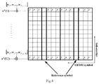
- FIG. 6 is a schematic diagram of mapping to a part of time-frequency resources according to an embodiment of the invention.
- FIG. 7 is a schematic structural diagram of a user equipment in an uplink transmission system according to an embodiment of the invention:
- FIG. 8 is a schematic structural diagram of a network-side device in an uplink transmission system according to an embodiment of the invention.
- FIG. 9 is a schematic flow chart of an uplink transmission method of a user equipment according to an embodiment of the invention.
- FIG. 10 is a schematic flow chart of an uplink transmission method of a network-side device according to an embodiment of the invention.
- a user equipment maps complex data symbols as a result of modulation onto Q sub-frames, where Q represents a positive integer; modulates the complex data symbols mapped onto each sub-frame respectively into a transmission signal corresponding to each sub-frame; and transmits the transmission signal in the corresponding sub-frame.
- data of a data packet is mapped into a plurality of sub-frames for transmission, and the total transmit power of the user equipment is increased by extending a signal in the time domain, thus ensuring the data transmitted by the user equipment to be received correctly, so as to improve the spectrum efficiency and the transmission efficiency of uplink transmission at the restricted power of uplink transmission.
- the embodiments of the invention use both Frequency Division Multiple Access (FDMA) and Code Division Multiple Access (CDMA) scheme or both Time Division Multiplex Access and CDMA scheme to support concurrent transmission of a plurality of user equipments in each sub-frame, thus ensuring the spectrum efficiency of the system.
- FDMA Frequency Division Multiple Access
- CDMA Code Division Multiple Access
- FIG. 1 there is a schematic diagram of signal transmission according to an embodiment of the invention, where uplink transmission is divided into five processes:
- an uplink transmission system includes a user equipment 10 and a network-side device 20 .
- the user equipment 10 is configured to map complex data symbols obtained by modulation onto Q sub-frames, where Q represents a positive integer: to modulate the complex data symbols mapped onto each sub-frame respectively into a transmission signal corresponding to each sub-frame; and to transmit the transmission signal in the corresponding sub-frame.
- the network-side device 20 is configured to de-spread the spread signals on the Q sub-frames to obtain de-spread data on the respective sub-frames, to combine the de-spread data in the Q sub-frames and to perform a reception process on the combined data.
- the value of Q can be set as needed, e.g., 4, 8, 16, 20, etc.; or can be determined dependent upon the following factors:
- a link quality condition of the user equipment 10 where the better link quality, the smaller the corresponding value of Q.
- the value of Q is determined by a received transmission parameter configured by the network-side device 20 for the user equipment 10 , or is fixed size pre-defined, or is determined under an agreed mapping rule of the value of Q to another parameter.
- the user equipment 10 maps the complex data symbols obtained by modulation onto the Q sub-frames, two of which may be listed below:
- the first scheme the user equipment 10 selects sequentially and maps the complex data symbols onto the Q sub-frames.
- the user equipment 10 divides sequentially the complex data symbols into a plurality of groups, each of which is mapped onto a sub-frame, according to the preset number of data symbols mapped onto a sub-frame. For example, if there are 100 complex data symbols, and the number of symbols mapped to each sub-frame is 10, then the symbols 1 to 10 are mapped onto a sub-frame, the symbols 11 to 20 are mapped onto another sub-frame, and so on.
- the number of data symbols mapped to a sub-frame can be determined by the amount of transmitted data and the value of Q.
- x q (n) represents a n-th complex data symbol mapped onto a sub-frame q
- d(q ⁇ M sym SF +n) represents a (q ⁇ M sym SF +n)-th complex data symbol
- M sym SF represents the amount of complex data symbols mapped onto the sub-frame q
- the network-side device 20 combines the de-spread data on the Q sub-frames in the order of sub-frames.
- the first to tenth data in the combined data sequence are the de-spread data in the first sub-frame
- the eleventh to twentieth data are the de-spread data in the second sub-frame, and so on.
- the number of data symbols mapped to a sub-frame can be determined by the amount of transmitted data and the value of Q.
- Second scheme the user equipment 10 selects at an interval and maps the complex data symbols onto the Q sub-frames.
- the user equipment 10 divides the complex data symbols into a plurality of groups, each of which is mapped onto a sub-frame, at an interval of a preset number of symbols. For example, if there are 30 complex data symbols, and the interval of a preset number of symbols is 10, then the symbols 1, 11 and 21 are mapped onto a sub-frame, the symbols 2, 12 and 22 are mapped onto another sub-frame, and so on.
- interval of a number of symbols can be equal to the number Q of sub-frames, or derived from a transmission parameter configured by the network side.
- x q (n) represents the complex data symbol mapped onto a sub-frame q
- d(q+n ⁇ Q) represents the (q+n ⁇ Q)-th complex data symbol
- M sym SF represents the amount of complex data symbols mapped onto the sub-frame q
- M sym SF M sym /Q
- M sym represents the amount of complex data symbols
- the network-side device 20 selects at the interval and combines the de-spreaded data on the Q sub-frames.
- the first de-spread data in each sub-frame of sub-frames 1 to 10 is arranged in sequence at the first to tenth locations in the combined data
- the second de-spread data in each sub-frame of sub-frames 1 to 10 is arranged in sequence at the eleventh to twenty-first locations in the combined data, and so on, and finally the arranged data are combined.
- the user equipment 10 spreads the complex data symbol by a spread code to obtain a sequence of spread data corresponding to the complex data symbol, maps the sequence of spread data onto time-frequency resources and modulates the sequence of spread data on the time-frequency resources into Orthogonal Frequency Division Multiplexing (OFDM) symbols.
- OFDM Orthogonal Frequency Division Multiplexing
- a transmission signal in a sub-frame may be described taking the sub-frame q as an example, and the same may apply to generation of the other sub-frames, so a repeated description thereof may be omitted.
- Data symbols mapped to the sub-frame q are x q (0), . . . , x q (M sym q ⁇ 1). Assumed that Nsc data sub-carriers and L OFDM symbols for data transmission in a sub-frame in a transmission bandwidth range of the user equipment. Each data symbol is spread by a spread code with a length of N SF , where the spread code is represented as
- the sequence of spread data is mapped onto time-frequency resources under a specific rule.
- the sequence of spread data mapped onto each OFDM symbol is subjected to an OFDM modulation or Discrete Fourier Transformation-Spread-Orthogonal Frequency Division Multiplexing (DFT-S-OFDM) modulation to generate an OFDM symbol.
- DFT-S-OFDM Discrete Fourier Transformation-Spread-Orthogonal Frequency Division Multiplexing
- the user equipment 10 maps the sequence of spread data onto the time-frequency resources in three schemes, which may be listed below respectively.
- the user equipment 10 can map a sequence of spread data corresponding to a complex data symbol onto the same sub-carrier of different OFDM symbols through spreading in the time domain, particularly as illustrated in FIG. 3 .
- the user equipment 10 can transmit at most 12 data symbols in a sub-frame using a spread code, where a data symbol is transmitted over each sub-carrier.
- there may be a plurality of spread codes among transmission parameters so that the user equipment 10 can use the plurality of spread codes for a larger number of data symbols transmitted in each sub-frame.
- the user equipment 10 can map a sequence of spread data corresponding to a complex data symbol onto a plurality of sub-carriers of the same OFDM symbol through spreading in the frequency domain, particularly as illustrated in FIG. 4 .
- the user equipment 10 can transmit at most 12 data symbols in a sub-frame using a spread code, where a data symbol is transmitted in each OFDM symbol.
- there may be a plurality of spread codes among transmission parameters so that the user equipment 10 can use the plurality of spread codes for a larger number of data symbols transmitted in each sub-frame.
- the user equipment 10 can map a sequence of spread data corresponding to a complex data symbol onto a plurality of sub-carriers of a plurality of OFDM symbols through spreading in both the time and frequency domains, particularly as illustrated in FIG. 5 .
- the user equipment 10 can transmit at most one data symbol in a sub-frame using a spread code.
- a base station can configure the user equipment with a plurality of spread codes to increase the number of data symbols transmitted in each sub-frame.
- Spreading in both the time and frequency domains can be performed at two levels of spreading, that is, firstly a data symbol is spread at a first level using a frequency (or time)-spread sequence, and then the spread sequence is spread at a second level using a time (or frequency)-spread sequence, particularly as illustrated in FIG. 5 .
- the user equipment 10 can map the sequence of spread data onto the time-frequency resources by mapping the sequence of spread data onto all or a part of the time-frequency resources.
- the user equipment 10 can map the sequence of spread data onto all of the time-frequency resources or a part of the time-frequency resources by selecting the length of the spread code.
- a plurality of data symbols of the user equipment can be transmitted concurrently over different time-frequency resources. For example, four data symbols are mapped respectively to four time-frequency zones through spreading, particularly as illustrated in FIG. 6 .
- the user equipment 10 further needs to perform channel encoding, scrambling and modulation before mapping the complex data symbols obtained by modulation onto the Q sub-frame, particularly as illustrated in FIG. 1 :
- Channel encoding a source data block including N-bit data s(0), . . . , s(N bit ⁇ 1) is channel-encoded into a data block with the length of M bits b(0), . . . , b (M bit ⁇ 1);
- the channel-encoded data block b(0), . . . , b (M bit ⁇ 1) is scrambled into a scrambled data block ⁇ dot over (b) ⁇ (0), . . . , ⁇ dot over (b) ⁇ (M bit ⁇ 1).
- Constellation mapping the scrambled data block ⁇ dot over (b) ⁇ (0), . . . , ⁇ dot over (b) ⁇ (M bit ⁇ 1) is constellation-mapped into a complex data symbol block d(0), . . . , d (M sym ⁇ 1) including M sym complex data symbols.
- a particular mapping scheme can be Binary Phase Shift Keying (BPSK), Quadrature Phase Shift Keying (QPSK), 16-Quadrature Amplitude Modulation (16QAM), 64QAM, etc.
- the network-side device 20 performs the reception process on the combined data by performing:
- the user equipment 10 and the network-side device 20 can perform the transmission process above according to transmission parameters.
- the transmission parameters include but may not be limited to at least one of the following information:
- the number of bundled sub-frames i.e., the value of Q
- the amount of complex data symbols mapped onto a sub-frame time-frequency resources occupied in each sub-frame (i.e., a spreading scheme), a spread code
- a mapped sub-frame(s) mapped sub-frames are separate in time domain
- a mapped first sub-frame mapped sub-frames are consecutive
- a mapping scheme to a sub-frame the number of data symbols mapped to a sub-frame in the course of mapping to the sub-frame, an interval of a number of symbols in the course of mapping to a sub-frame, and a mapping scheme to time-frequency resources.
- the transmission parameters can be defined in a protocol in advance or can be configured by the network-side device 20 : or a part of information in the transmission parameters can be defined in the protocol in advance, and another part of the information can be configured by the network-side device 20 . Either of the options will be possible as long as the same parameters are determined by the user equipment 10 and the network-side device 20 for uplink transmission.
- the network-side device 20 configures the user equipment 10 with the transmission parameters.
- the network-side device 20 configures the user equipment with the transmission parameters semi-statically in higher-layer signaling: or configures the user equipment with the transmission parameters in control signaling to schedule uplink transmission.
- those sub-frames to which the user equipment 10 maps the data respectively can be known due to the knowledge of the transmission parameters of the user equipment 10 , and correspondingly the network-side device 20 can obtain and combine the data from the user equipment in the corresponding sub-frames and de-spread and further perform the reception process on the combined data.
- the network-side device can be a base station (e.g., a macro base station, a femto base station, etc.) or can be a Relay Node (RN) device or can be another network-side device.
- a base station e.g., a macro base station, a femto base station, etc.
- RN Relay Node
- a user equipment in an uplink transmission system includes a first processing module 700 , a modulation module 710 and a transmission module 720 .
- the first processing module 700 is configured to map complex data symbols obtained by modulation onto Q sub-frames, where Q represents a positive integer;
- the modulation module 710 is configured to modulate the complex data symbols mapped onto each sub-frame respectively into a transmission signal corresponding to each sub-frame;
- the transmission module 720 is configured to transmit the transmission signal in the corresponding sub-frame.
- the first processing module 700 determines the value of Q from a transmission parameter
- the first processing module 700 maps the complex data symbols obtained by modulation onto the Q sub-frames in a number of schemes, two of which will be listed below:
- the first processing module 700 selects sequentially and maps the complex data symbols onto the Q sub-frames.
- the first processing module 700 determines complex data symbols to be mapped to the sub-frame by the equation 1.
- the first processing module 700 selects at an interval and maps the complex data symbols onto the Q sub-frames.
- the first processing module 700 determines complex data symbols to be mapped to the sub-frame by the equation 3.
- the modulation module 710 spreads the complex data symbol by a spread code to obtain a sequence of spread data corresponding to the complex data symbol, maps the sequence of spread data onto time-frequency resources and modulates the sequence of spread data on the time-frequency resources to generate Orthogonal Frequency Division Multiplexing (OFDM) symbols.
- OFDM Orthogonal Frequency Division Multiplexing
- the modulation module 710 maps the sequence of spread data onto all or a part of the time-frequency resources.
- the modulation module 710 maps a sequence of spread data corresponding to a complex data symbol onto the same sub-carrier of different OFDM symbols through spreading in the time domain; or maps a sequence of spread data corresponding to a complex data symbol onto a plurality of sub-carriers of the same OFDM symbol through spreading in the frequency domain; or maps a sequence of spread data corresponding to a complex data symbol onto a plurality of sub-carriers of a plurality of OFDM symbols through spreading in both the time and frequency domains.
- the modulation module 710 determines time-frequency resources in each sub-frame according to transmission parameters.
- a network-side device in an uplink transmission system includes a reception module 800 and a second processing module 810 .
- the reception module 800 is configured to de-spread spread signals on Q sub-frames to obtain de-spread data on the respective sub-frames, where Q represents a positive integer;
- the second processing module 810 is configured to combine the de-spread data on the Q sub-frames and to perform a reception process on the combined data.
- the second processing module 810 combines the de-spread data on the Q sub-frames in the order of sub-frames.
- the second processing module 810 combines obtained transmission signals by the equation 2.
- the second processing module 810 selects at an interval and combines the de-spread data on the Q sub-frames.
- the second processing module 810 combines obtained transmission signals by the equation 4.
- the network-side device can further include a notification module 820 .
- the notification module 820 is configured to configure a user equipment with transmission parameters.
- the notification module 820 configures the user equipment with the transmission parameters semi-statically in higher-layer signaling; or configures the user equipment with the transmission parameters in control signaling which schedules uplink transmission.
- embodiments of the invention further provide an uplink transmission method of a user equipment and an uplink transmission method of a network-side device, and since these methods address the problem under a similar principle to the uplink transmission system according to the embodiment of the invention, reference can be made to the implementation of the system for implementations of these methods, so a repeated description thereof will be omitted here.
- an uplink transmission method of a user equipment includes the operations:
- the user equipment maps complex data symbols obtained by modulation onto Q sub-frames, where Q represents a positive integer
- the user equipment modulates the complex data symbols mapped onto each sub-frame respectively into a transmission signal corresponding to each sub-frame;
- the user equipment transmits the transmission signal in the corresponding sub-frame.
- the user equipment maps the complex data symbols obtained by modulation onto the Q sub-frames in a number of schemes, two of which may be listed below:
- the user equipment selects sequentially and maps the complex data symbols onto the Q sub-frames.
- the user equipment divides sequentially the complex data symbols into a plurality of groups, each of which is mapped onto a sub-frame, according to the preset number of data symbols mapped onto a sub-frame. For example, if there are 100 complex data symbols, and the number of data symbols mapped to a sub-frame is 10, then the symbols 1 to 10 are mapped onto a sub-frame, the symbols 11 to 20 are mapped onto another sub-frame, and so on.
- the number of data symbols mapped to a sub-frame can be determined by the amount of transmitted data and the value of Q.
- the user equipment can determine complex data symbols to be mapped to the sub-frame by the equation 1.
- the user equipment selects at an interval and maps the complex data symbols onto the Q sub-frames.
- the user equipment divides the complex data symbols into a plurality of groups, each of which is mapped onto a sub-frame, at an interval of a preset number of symbols.
- the symbols 1, 11 and 21 are mapped onto a sub-frame
- the symbols 2, 12 and 22 are mapped onto another sub-frame, and so on.
- interval of a number of symbols can be equal to the number Q of sub-frames or derived from a transmission parameter configured by the network side.
- the user equipment can determine complex data symbols to be mapped to the sub-frame by the equation 3.
- the user equipment spreads the complex data symbol by a spread code to obtain a sequence of spread data corresponding to the complex data symbol, maps the sequence of spread data onto time-frequency resources and modulates the sequence of spread data on the time-frequency resources to generate OFDM symbols.
- a transmission signal in a sub-frame may be described taking a sub-frame q as an example, and the same may apply to generation of the other sub-frames, so a repeated description thereof may be omitted.
- Data symbols mapped to the sub-frame q are x q (0), . . . , x q (M sym q ⁇ 1).
- Nsc data sub-carriers and L OFDM symbols for data transmission in a sub-frame in a transmission bandwidth range of the user equipment Each data symbol is spread by a spread code with the length of N SF , where the spread code is represented as
- the sequence of spread data is mapped onto time-frequency resources under a specific rule.
- the sequence of spread data mapped onto each OFDM symbol is subjected to an OFDM modulation or DFT-S-OFDM modulation to generate an OFDM symbol.
- the user equipment maps the sequence of spread data onto the time-frequency resources in three schemes, which may be listed below respectively.
- the user equipment can map a sequence of spread data corresponding to a complex data symbol onto the same sub-carrier of different OFDM symbols through spreading in the time domain, particularly as illustrated in FIG. 3 .
- the user equipment 10 can map a sequence of spread data corresponding to a complex data symbol onto a plurality of sub-carriers of the same OFDM symbol through spreading in the frequency domain, particularly as illustrated in FIG. 4 .
- the user equipment 10 can map a sequence of spread data corresponding to a complex data symbol onto a plurality of sub-carriers of a plurality of OFDM symbols through spreading in both the time and frequency domains, particularly as illustrated in FIG. 5 .
- the user equipment can map the sequence of spread data onto the time-frequency resources by mapping the sequence of spread data onto all or a part of the time-frequency resources.
- the user equipment can map the sequence of spread data onto all of the time-frequency resources or a part of the time-frequency resources by selecting the length of the spread code.
- a plurality of data symbols of the user equipment can be transmitted concurrently over different time-frequency resources. For example, four data symbols are mapped respectively to four time-frequency zones through spreading, particularly as illustrated in FIG. 6 .
- the user equipment further needs to perform channel encoding, scrambling and modulation before the operation 901 , particularly as illustrated in FIG. 1 :
- Channel encoding a source data block including N-bit data s(0), . . . , s(N bit ⁇ 1) is channel-encoded into a data block with the length of M bits b(0), . . . , b (M bit ⁇ 1);
- the channel-encoded data block b(0), . . . , b (M bit ⁇ 1) is scrambled into a scrambled data block ⁇ dot over (b) ⁇ (0), . . . , ⁇ dot over (b) ⁇ (M bit ⁇ 1).
- Constellation mapping the scrambled data block ⁇ dot over (b) ⁇ (0), . . . , ⁇ dot over (b) ⁇ (M bit ⁇ 1) is constellation-mapped into a complex data symbol block d(0), . . . , d (M sym ⁇ 1) including M sym complex data symbols.
- a particular mapping scheme can be BPSK, QPSK, 16QAM, 64QAM, etc.
- the transmission parameters can be defined in a protocol in advance or can be configured by a network-side device; or a part of information in the transmission parameters can be defined in the protocol in advance, and another part of the information can be configured by the network-side device. Either of the options will be possible as long as the same parameters are determined by the user equipment and the network-side device for uplink transmission.
- those sub-frames to which the user equipment maps the data respectively can be known due to the knowledge of the transmission parameters of the user equipment, and correspondingly the network-side device can obtain and combine the data from the user equipment in the corresponding sub-frames and de-spread and further perform the reception process on the combined data.
- an uplink transmission method of a network-side device includes the following operations:
- the network-side device de-spreads spread signals on Q sub-frames to obtain de-spread data on the respective sub-frames, where Q represents a positive integer;
- the network-side device combines the de-spread data on the Q sub-frames and performs a reception process on the combined data.
- the network-side device combines the de-spread data on the Q sub-frames in the order of sub-frames.
- the first to tenth data in the combined sequence of data are the de-spread data in the first sub-frame
- the eleventh to twentieth data are the de-spread data in the second sub-frame, and so on.
- the number of data symbols mapped to a sub-frame can be determined by the amount of transmitted data and the value of Q.
- the network-side device combines obtained transmission signals by the equation 2.
- the network-side device combines the de-spread data on the Q sub-frames at the interval.
- the network-side device extracts at the interval of a preset number of symbols and then combines the de-spread data in the Q sub-frames. If there are 30 complex data symbols, and the interval of a preset number of symbols is 10, then the first, eleventh and twenty-first symbols are arranged at the front, the second, twelfth and twenty-second symbols are arranged next, and so on, and finally the arranged data are combined.
- interval of a number of symbols can be equal to the number Q of sub-frames or derived from a transmission parameter configured by the network side.
- the network-side device combines obtained transmission signals by the equation 4.
- the network-side device performs the reception process on the combined data by performing:
- network-side device can perform the transmission process above according to transmission parameters.
- the transmission parameters can be defined in a protocol in advance or can be configured by the network-side device; or a part of information in the transmission parameters can be defined in the protocol in advance, and another part of the information can be configured by the network-side device. Either of the options will be possible as long as the same parameters are determined by the user equipment and the network-side device for uplink transmission.
- the network-side device configures the user equipment with the transmission parameters.
- the network-side device configures the user equipment with the transmission parameters semi-statically in higher-layer signaling; or configures the user equipment with the transmission parameters in control signaling which schedules uplink transmission.
- those sub-frames to which the user equipment maps the data respectively can be known due to the knowledge of the transmission parameters of the user equipment, and correspondingly the network-side device can obtain and combine the data from the user equipment in the corresponding sub-frames and de-spread and further perform the reception process on the combined data.
- the embodiments of the invention can be embodied as a method, a system or a computer program product. Therefore the invention can be embodied in the form of an all-hardware embodiment, an all-software embodiment or an embodiment of software and hardware in combination. Furthermore the invention can be embodied in the form of a computer program product embodied in one or more computer useable storage mediums (including but not limited to a disk memory, a CD-ROM, an optical memory, etc.) in which computer useable program codes are contained.
- a computer useable storage mediums including but not limited to a disk memory, a CD-ROM, an optical memory, etc.
- These computer program instructions can also be stored into a computer readable memory capable of directing the computer or the other programmable data processing device to operate in a specific manner so that the instructions stored in the computer readable memory create an article of manufacture including instruction means which perform the functions specified in the flow(s) of the flow chart and/or the block(s) of the block diagram.
- These computer program instructions can also be loaded onto the computer or the other programmable data processing device so that a series of operational steps are performed on the computer or the other programmable data processing device to create a computer implemented process so that the instructions executed on the computer or the other programmable device provide steps for performing the functions specified in the flow(s) of the flow chart and/or the block(s) of the block diagram.
Landscapes
- Engineering & Computer Science (AREA)
- Signal Processing (AREA)
- Computer Networks & Wireless Communication (AREA)
- Physics & Mathematics (AREA)
- Discrete Mathematics (AREA)
- General Physics & Mathematics (AREA)
- Mathematical Physics (AREA)
- Mobile Radio Communication Systems (AREA)
Abstract
Description
x q(n)=d(q×M sym SF +n)
d(m)=x q(n)
x q(n)=d(q+n×Q) Equation 3;
d(m)=x q(n) Equation 4;
and xq(n) is spread into a sequence of spread data yq(n,l)=xq(n)wl. The sequence of spread data is mapped onto time-frequency resources under a specific rule. The sequence of spread data mapped onto each OFDM symbol is subjected to an OFDM modulation or Discrete Fourier Transformation-Spread-Orthogonal Frequency Division Multiplexing (DFT-S-OFDM) modulation to generate an OFDM symbol.
and xq(n) is spread into a sequence of spread data yq(n,l)=xq(n)wl. The sequence of spread data is mapped onto time-frequency resources under a specific rule. The sequence of spread data mapped onto each OFDM symbol is subjected to an OFDM modulation or DFT-S-OFDM modulation to generate an OFDM symbol.
Claims (10)
x q(n)=d(q×M sym SF +n),
x q(n)=d(q+n×Q),
d(m)=x q(n),
d(m)=x q(n),
x q(n)=d(q×M syn SF +n),
x q(n)=d(q+n×Q),
d(m)=x q(n),
d(m)=x q(n),
Applications Claiming Priority (4)
| Application Number | Priority Date | Filing Date | Title |
|---|---|---|---|
| CN201210129085.4 | 2012-04-27 | ||
| CN201210129085 | 2012-04-27 | ||
| CN201210129085.4A CN103379076B (en) | 2012-04-27 | 2012-04-27 | A kind of carry out the method for uplink, system and equipment |
| PCT/CN2013/074776 WO2013159733A1 (en) | 2012-04-27 | 2013-04-26 | Method, system, and device for performing uplink transmission |
Publications (2)
| Publication Number | Publication Date |
|---|---|
| US20150071365A1 US20150071365A1 (en) | 2015-03-12 |
| US9325464B2 true US9325464B2 (en) | 2016-04-26 |
Family
ID=49463641
Family Applications (1)
| Application Number | Title | Priority Date | Filing Date |
|---|---|---|---|
| US14/397,199 Active US9325464B2 (en) | 2012-04-27 | 2013-04-26 | Method, system, and device for performing uplink transmission |
Country Status (5)
| Country | Link |
|---|---|
| US (1) | US9325464B2 (en) |
| EP (1) | EP2854298B1 (en) |
| CN (1) | CN103379076B (en) |
| TW (1) | TWI558139B (en) |
| WO (1) | WO2013159733A1 (en) |
Families Citing this family (3)
| Publication number | Priority date | Publication date | Assignee | Title |
|---|---|---|---|---|
| US20170064695A1 (en) * | 2015-08-25 | 2017-03-02 | Qualcomm Incorporated | Transmission parameter control for immediate response frames |
| WO2017068747A1 (en) | 2015-10-20 | 2017-04-27 | パナソニック インテレクチュアル プロパティ コーポレーション オブ アメリカ | Communication device and communication method |
| CN107846726B (en) * | 2016-09-19 | 2019-08-09 | 上海朗帛通信技术有限公司 | Method and device for adjusting transmit power in UE and base station |
Citations (9)
| Publication number | Priority date | Publication date | Assignee | Title |
|---|---|---|---|---|
| WO2005013530A2 (en) | 2003-07-28 | 2005-02-10 | Motorola, Inc. | Ofdm communication system |
| CN1694441A (en) | 2005-05-25 | 2005-11-09 | 上海贝豪通讯电子有限公司 | Method for compatible OFDM technology by TD-SCDMA system |
| WO2008031111A1 (en) | 2006-09-08 | 2008-03-13 | Qualcomm Incorporated | Signaling transmission with localized spreading for wireless communication |
| US20080232449A1 (en) * | 2007-03-21 | 2008-09-25 | Farooq Khan | Efficient uplink feedback in a wireless communication system |
| US20090186613A1 (en) * | 2008-01-04 | 2009-07-23 | Ahn Seung Jin | Method of performing random access procedure in wireless communication system |
| CN101610463A (en) | 2008-06-19 | 2009-12-23 | 中兴通讯股份有限公司 | A method for sending wireless data |
| US20120039270A1 (en) * | 2010-08-12 | 2012-02-16 | Samsung Electronics Co., Ltd. | Methods and apparatus for uplink control transmit diversity |
| US20120140716A1 (en) * | 2010-12-03 | 2012-06-07 | Telefonaktiebolaget L M Ericsson (Publ) | Method and Arrangement for Transmitting Uplink Control |
| US20120263124A1 (en) * | 2010-10-11 | 2012-10-18 | Qualcomm Incorporated | Resource assignments for uplink control channel |
Family Cites Families (4)
| Publication number | Priority date | Publication date | Assignee | Title |
|---|---|---|---|---|
| SE523638C2 (en) * | 2001-09-28 | 2004-05-04 | Ericsson Telefon Ab L M | Switch based on multi-mode interference waveguides |
| KR100615139B1 (en) * | 2005-10-18 | 2006-08-22 | 삼성전자주식회사 | Method and apparatus for allocating transmission period in wireless telecommunication system and therefor system |
| KR101333725B1 (en) * | 2006-06-30 | 2013-11-28 | 삼성전자주식회사 | Verification method and verifier |
| CN101616491A (en) * | 2008-06-25 | 2009-12-30 | 三星电子株式会社 | Method for mapping uplink ACK/NACK channel |
-
2012
- 2012-04-27 CN CN201210129085.4A patent/CN103379076B/en active Active
-
2013
- 2013-04-26 WO PCT/CN2013/074776 patent/WO2013159733A1/en not_active Ceased
- 2013-04-26 US US14/397,199 patent/US9325464B2/en active Active
- 2013-04-26 TW TW102114976A patent/TWI558139B/en active
- 2013-04-26 EP EP13781039.6A patent/EP2854298B1/en active Active
Patent Citations (11)
| Publication number | Priority date | Publication date | Assignee | Title |
|---|---|---|---|---|
| WO2005013530A2 (en) | 2003-07-28 | 2005-02-10 | Motorola, Inc. | Ofdm communication system |
| CN1694441A (en) | 2005-05-25 | 2005-11-09 | 上海贝豪通讯电子有限公司 | Method for compatible OFDM technology by TD-SCDMA system |
| WO2008031111A1 (en) | 2006-09-08 | 2008-03-13 | Qualcomm Incorporated | Signaling transmission with localized spreading for wireless communication |
| US20080101441A1 (en) * | 2006-09-08 | 2008-05-01 | Qualcomm Incorporated | Signaling transmission with localized spreading for wireless communication |
| US20080232449A1 (en) * | 2007-03-21 | 2008-09-25 | Farooq Khan | Efficient uplink feedback in a wireless communication system |
| CN101636995A (en) | 2007-03-21 | 2010-01-27 | 三星电子株式会社 | Efficient uplink feedback in a wireless communication system |
| US20090186613A1 (en) * | 2008-01-04 | 2009-07-23 | Ahn Seung Jin | Method of performing random access procedure in wireless communication system |
| CN101610463A (en) | 2008-06-19 | 2009-12-23 | 中兴通讯股份有限公司 | A method for sending wireless data |
| US20120039270A1 (en) * | 2010-08-12 | 2012-02-16 | Samsung Electronics Co., Ltd. | Methods and apparatus for uplink control transmit diversity |
| US20120263124A1 (en) * | 2010-10-11 | 2012-10-18 | Qualcomm Incorporated | Resource assignments for uplink control channel |
| US20120140716A1 (en) * | 2010-12-03 | 2012-06-07 | Telefonaktiebolaget L M Ericsson (Publ) | Method and Arrangement for Transmitting Uplink Control |
Non-Patent Citations (2)
| Title |
|---|
| Extended European Search Report issued on Jun. 1, 2015 in the EP counterpart application (13781039.6). |
| International Search Report for PCT/CN2013/074776. |
Also Published As
| Publication number | Publication date |
|---|---|
| CN103379076A (en) | 2013-10-30 |
| TW201401822A (en) | 2014-01-01 |
| CN103379076B (en) | 2016-09-28 |
| EP2854298A4 (en) | 2015-07-01 |
| EP2854298B1 (en) | 2016-10-19 |
| EP2854298A1 (en) | 2015-04-01 |
| TWI558139B (en) | 2016-11-11 |
| WO2013159733A1 (en) | 2013-10-31 |
| US20150071365A1 (en) | 2015-03-12 |
Similar Documents
| Publication | Publication Date | Title |
|---|---|---|
| US8934429B2 (en) | Wireless communication system, base station apparatus, mobile station apparatus, wireless communication method and integrated circuit | |
| US9197385B2 (en) | Systems and methods for demodulation reference signal selection | |
| KR101591086B1 (en) | Method of performing harq in multiple antenna system | |
| CN107690764B (en) | Short PUCCH in uplink SPUCCH | |
| DK2526643T3 (en) | Radio base station and user device and methods therein | |
| KR101543456B1 (en) | Scrambled transmission method and device thereof | |
| RU2548657C2 (en) | Mobile terminal and radio communication method | |
| EP3396914A1 (en) | Base station device, terminal device, and communication method | |
| US20140044064A1 (en) | Resource allocation including a dc sub-carrier in a wireless communication system | |
| JP2010533408A (en) | Apparatus and method for transmitting / receiving uplink control channel in wireless communication system | |
| KR20160053562A (en) | Low Data Rate Transmission in LTE Based Satellite Radio Interface | |
| US8588153B2 (en) | Method and apparatus for transmitting uplink control channel in a mobile communication system | |
| US9325464B2 (en) | Method, system, and device for performing uplink transmission | |
| JP5570567B2 (en) | Base station apparatus, mobile station apparatus, wireless communication method, and integrated circuit | |
| KR20100103310A (en) | Method and apparatus for transmitting and receiving response channel resource between enb and user equipment in ofdm wireless telecommunication system | |
| HK1180845B (en) | Radio base station and user equipment and methods therein |
Legal Events
| Date | Code | Title | Description |
|---|---|---|---|
| AS | Assignment |
Owner name: CHINA ACADEMY OF TELECOMMUNICATIONS TECHNOLOGY, CH Free format text: ASSIGNMENT OF ASSIGNORS INTEREST;ASSIGNORS:GAO, QIUBIN;ZHOU, HAIJUN;QIN, FEI;AND OTHERS;REEL/FRAME:034056/0022 Effective date: 20141021 |
|
| STCF | Information on status: patent grant |
Free format text: PATENTED CASE |
|
| MAFP | Maintenance fee payment |
Free format text: PAYMENT OF MAINTENANCE FEE, 4TH YEAR, LARGE ENTITY (ORIGINAL EVENT CODE: M1551); ENTITY STATUS OF PATENT OWNER: LARGE ENTITY Year of fee payment: 4 |
|
| AS | Assignment |
Owner name: DATANG MOBILE COMMUNICATIONS EQUIPMENT CO.,LTD., CHINA Free format text: ASSIGNMENT OF ASSIGNORS INTEREST;ASSIGNOR:CHINA ACADEMY OF TELECOMMUNICATIONS TECHNOLOGY;REEL/FRAME:057452/0169 Effective date: 20210622 |
|
| MAFP | Maintenance fee payment |
Free format text: PAYMENT OF MAINTENANCE FEE, 8TH YEAR, LARGE ENTITY (ORIGINAL EVENT CODE: M1552); ENTITY STATUS OF PATENT OWNER: LARGE ENTITY Year of fee payment: 8 |