US9325227B2 - Cutting apparatus - Google Patents
Cutting apparatus Download PDFInfo
- Publication number
- US9325227B2 US9325227B2 US13/784,892 US201313784892A US9325227B2 US 9325227 B2 US9325227 B2 US 9325227B2 US 201313784892 A US201313784892 A US 201313784892A US 9325227 B2 US9325227 B2 US 9325227B2
- Authority
- US
- United States
- Prior art keywords
- shaft
- cutting
- motor
- sleeve
- guide
- Prior art date
- Legal status (The legal status is an assumption and is not a legal conclusion. Google has not performed a legal analysis and makes no representation as to the accuracy of the status listed.)
- Expired - Fee Related, expires
Links
Images


Classifications
-
- H02K15/0006—
-
- H—ELECTRICITY
- H02—GENERATION; CONVERSION OR DISTRIBUTION OF ELECTRIC POWER
- H02K—DYNAMO-ELECTRIC MACHINES
- H02K15/00—Processes or apparatus specially adapted for manufacturing, assembling, maintaining or repairing of dynamo-electric machines
- H02K15/50—Disassembling, repairing or modifying dynamo-electric machines
-
- F—MECHANICAL ENGINEERING; LIGHTING; HEATING; WEAPONS; BLASTING
- F04—POSITIVE - DISPLACEMENT MACHINES FOR LIQUIDS; PUMPS FOR LIQUIDS OR ELASTIC FLUIDS
- F04D—NON-POSITIVE-DISPLACEMENT PUMPS
- F04D29/00—Details, component parts, or accessories
- F04D29/05—Shafts or bearings, or assemblies thereof, specially adapted for elastic fluid pumps
- F04D29/053—Shafts
-
- F—MECHANICAL ENGINEERING; LIGHTING; HEATING; WEAPONS; BLASTING
- F05—INDEXING SCHEMES RELATING TO ENGINES OR PUMPS IN VARIOUS SUBCLASSES OF CLASSES F01-F04
- F05D—INDEXING SCHEME FOR ASPECTS RELATING TO NON-POSITIVE-DISPLACEMENT MACHINES OR ENGINES, GAS-TURBINES OR JET-PROPULSION PLANTS
- F05D2230/00—Manufacture
- F05D2230/70—Disassembly methods
-
- F—MECHANICAL ENGINEERING; LIGHTING; HEATING; WEAPONS; BLASTING
- F05—INDEXING SCHEMES RELATING TO ENGINES OR PUMPS IN VARIOUS SUBCLASSES OF CLASSES F01-F04
- F05D—INDEXING SCHEME FOR ASPECTS RELATING TO NON-POSITIVE-DISPLACEMENT MACHINES OR ENGINES, GAS-TURBINES OR JET-PROPULSION PLANTS
- F05D2230/00—Manufacture
- F05D2230/80—Repairing, retrofitting or upgrading methods
-
- H—ELECTRICITY
- H02—GENERATION; CONVERSION OR DISTRIBUTION OF ELECTRIC POWER
- H02K—DYNAMO-ELECTRIC MACHINES
- H02K7/00—Arrangements for handling mechanical energy structurally associated with dynamo-electric machines, e.g. structural association with mechanical driving motors or auxiliary dynamo-electric machines
- H02K7/14—Structural association with mechanical loads, e.g. with hand-held machine tools or fans
-
- Y—GENERAL TAGGING OF NEW TECHNOLOGICAL DEVELOPMENTS; GENERAL TAGGING OF CROSS-SECTIONAL TECHNOLOGIES SPANNING OVER SEVERAL SECTIONS OF THE IPC; TECHNICAL SUBJECTS COVERED BY FORMER USPC CROSS-REFERENCE ART COLLECTIONS [XRACs] AND DIGESTS
- Y10—TECHNICAL SUBJECTS COVERED BY FORMER USPC
- Y10T—TECHNICAL SUBJECTS COVERED BY FORMER US CLASSIFICATION
- Y10T83/00—Cutting
- Y10T83/667—Tool carrier or guide affixed to work during cutting
-
- Y—GENERAL TAGGING OF NEW TECHNOLOGICAL DEVELOPMENTS; GENERAL TAGGING OF CROSS-SECTIONAL TECHNOLOGIES SPANNING OVER SEVERAL SECTIONS OF THE IPC; TECHNICAL SUBJECTS COVERED BY FORMER USPC CROSS-REFERENCE ART COLLECTIONS [XRACs] AND DIGESTS
- Y10—TECHNICAL SUBJECTS COVERED BY FORMER USPC
- Y10T—TECHNICAL SUBJECTS COVERED BY FORMER US CLASSIFICATION
- Y10T83/00—Cutting
- Y10T83/889—Tool with either work holder or means to hold work supply
Definitions
- the present invention relates to a cutting apparatus, more particularly to a cutting apparatus for cutting electric motor shafts.
- the present invention tends to provide a cutting apparatus for cutting electric motor shafts, making motor replacing easier, faster, and safer.
- a cutting apparatus for cutting electric motor shafts that generally includes a base member having a receptacle designed for receiving an accessory, for example a shaft cutting guide when cutting a shaft of an electric motor, or a shaft removal pedestal when cutting a shaft of an electric fan motor.
- the base member includes a first support in parallel relation to a second support, and a first feet member in parallel relation to a second feet member, where the first and second supports are connected to and in perpendicular relation to the first and second feet members.
- the receptacle is centrally disposed on the first feet member.
- the receptacle defines a chamber and a bore for threadably receiving a wing screw, the wing screw for releasably securing the accessory received in the chamber of the receptacle.
- the shaft cutting guide includes a sleeve sized and shaped for receiving a motor's shaft.
- the sleeve includes a bore for threadably receiving a wing screw, the wing screw for releasably securing the motor's shaft received in the sleeve.
- the sleeve further defines a blade guide for guiding a cutting tool during the cutting operation.
- the shaft cutting guide further includes a mounting shaft sized and shaped for receipt in the chamber of the receptacle.
- FIG. 1 is a perspective view of a cutting apparatus in accordance with the present invention.
- FIG. 1 a is a perspective view of a shaft cutting guide used with the cutting apparatus of FIG. 1 .
- FIG. 2 is a side view of a shaft removal pedestal, a punch guide, and punch.
- FIG. 3 is a perspective view of a handle with a shaft cutting guide attached.
- FIG. 4 is a perspective view of a handle with shaft cutting guide attached, installed on a motor's shaft of a motor.
- FIG. 5 is a perspective view of a motor on the cutting apparatus of FIG. 1 , and further illustrates the motor's shaft inserted in the shaft cutting guide to be cut.
- FIG. 6 is a perspective view of a fan blade installed on a shaft removal pedestal on the cutting apparatus of FIG. 1 .
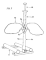
- FIG. 7 is a perspective view of a fan blade installed on shaft removal pedestal on the cutting apparatus, with a punch guide and a steel punch installed on top of the fan blade hub.
- FIG. 8 is a perspective view of an alternative embodiment of the present invention.
- FIG. 9 is a perspective view of an alternative embodiment of the present invention, having extendable support members.
- the apparatus of the present invention is directed to a cutting tool that is used in association with cutting electric motor shafts. More particularly, the described cutting apparatus relates to a tool used to keep the electric motor from moving, shaft from spinning, and saw blades from sliding on the shaft when cutting the motor's shaft. Specifically, it will be noted in the following description that the present invention discloses a tool that supports and cradles the motor and fixedly secures the motor's shaft during the cutting operation. In the broadest context, the cutting apparatus as disclosed consists of components configured and correlated with respect to each other so as to attain the desired objective.
- FIGS. 1-7 illustrate a preferred embodiment of a cutting apparatus made in accordance with the present invention.
- the apparatus generally consisting of the following components:
- Base 10 holds the motor stationary during the cutting operation.
- Receptacle 20 for attaching an accessory, such as the shaft cutting guide 30 , or shaft removal pedestal 40 to the base 10 .
- Shaft cutting guide 30 aligns & guides the cutting tool when cutting a motor shaft.
- Shaft removal pedestal 40 supports the fan blade so the shaft being removed from the fan blade can be punched out of the fan blade hub.
- Punch guide 50 aligns & guides punch 60 when driving out the shaft being removed from the fan blade.
- Handle 70 used with shaft cutting guide 30 when not using the base 10 .
- Base consists of two motor supports 12 running parallel to each other to cradle the motor 90 .
- Supports 12 can be made with pipe, angle, or other shapes that would cradle the motor 90 and prevent the motor 90 from rolling.
- a pair of feet 14 connects to the supports 12 at right angles toward the ends 12 a of 12 b of the supports 12 .
- the pair of feet 14 should extend past supports 12 to allow for mounting holes 17 .
- the pair of feet 14 should be magnetized or incorporate magnets 16 to secure base 10 to metal surfaces such as truck beds, van floors, steel tables, etc. (not shown).
- the pair of feet 14 may further include skid resistant pads or covers 18 to further prevent movement when being used.
- the supports 12 may display scale measurements 15 starting in line with blade guide 34 when shaft cutting guide 30 is installed in receptacle 20 .
- the feet 14 may be integral to the supports 12 .
- FIG. 9 illustrates a second alternative embodiment, wherein each of the supports 12 includes telescopic extensions 12 a that connect to a third feet 14 a .
- a second receptacle 20 a can be centrally disposed on the third feet 14 a .
- the second receptacle 20 a having all the embodiments as the receptacle 20 .
- Receptacle 20
- Receptacle 20 consists of a hub 22 with accessory chamber 24 (which could be round, square, hexagon, etc.) to releasably attach the shaft cutting guide 30 , the shaft removal pedestal 40 , or other accessory to the base 10 .
- a wing screw 28 (or other means of securing) facing outward secures the accessory within the chamber 24 .
- receptacle 20 is permanently attached to one of the feet 14 centered between the two supports 12 .
- receptacle 20 is integral to one of the feet 14 of the base 10 (see FIG. 8 ).
- Shaft cutting guide 30 consists of a sleeve 32 sized for receiving the motor's shaft 92 for cutting.
- a wing screw 38 (or other means of securing) is received in threaded bore 38 a to secure the motor's shaft 92 in the sleeve 32 .
- Adjacent the sleeve 32 is the blade guide 34 for guiding a cutting tool such as a hacksaw, or reciprocating saw (not shown) at a right angle to the motor's shaft 92 .
- the cutting guide 30 should be made of hardened steel for quality and endurance. As illustrated, the blade guide 34 defines a length 34 a that in application, is perpendicular to the motor's shaft 92 (see FIG. 5 ).
- the shaft cutting guide 30 further includes a mounting shaft 36 sized and shaped for inserting into the chamber 24 of the receptacle 20 .
- Shaft removal pedestal 40 consists of a sleeve 42 that includes an inside chamber 48 that is slightly larger than the shaft 98 being removed from a fan blade 94 such that in application, the shaft 98 can be inserted into pedestal 40 and drove down out of the fan blade 94 and into pedestal 40 .
- the hub support 44 is preferably large enough to support fan blade hub 96 while shaft 98 is being removed.
- the hub support 44 having a distal end 44 a that includes magnets 44 b to help secure and balance the fan blade hub 96 until punch guide 50 is installed on top of hub 96 .
- Attached to the bottom of the shaft removal pedestal 40 is the mounting shaft 46 sized and shaped for inserting into the chamber 24 of the receptacle 20 .
- Punch guide 50 consists of a sleeve 52 that includes an inside chamber 58 that is slightly larger than the shaft 98 being removed from fan blade 94 such that in application, the punch guide 50 can be slid down over the shaft 98 and on top of the fan blade hub 96 .
- the punch guide 50 aligns punch 60 with center of shaft 98 and prevents punch 60 from kicking off or deforming the end of shaft 98 being removed.
- the protective flange 54 on top of punch guide 50 helps protect the user's hand and provide a stop for punch 60 .
- Punch 60 consists of staff 68 designed to close tolerances of chamber 58 of punch guide 50 so that in application, punch tip 66 stays aligned with the center of shaft 98 when being struck with the punch 60 .
- the staff 68 should be long enough to extend through punch guide 50 and fan blade hub 96 in order to extract shaft 98 from fan blade 94 .
- the punch 60 has a flanged head 64 for easier striking, and to stop punch 60 at protective flange 54 of punch guide 50 .
- Punch 60 should be made of hardened steel for quality and endurance.
- Handle 70 includes a swivel receptacle 72 having an accessory chamber 74 having the approximate same size and shape as accessory chamber 24 to attach shaft cutting guide 30 for using shaft cutting guide 30 without base 10 in situations where, for example, motor 90 may already be mounted to equipment.
- the opposite end of the handle 70 can be secured to the motor 90 to prevent the motor's shaft 92 and shaft cutting guide 30 from moving while cutting the shaft 92 . This may be accomplished by magnetizing the handle 70 or by clamping the handle 70 to the motor 90 with means of a band clamp, hook & loop strap, elastic band, etc.
- the handle 70 might be adjustable in length to be more versatile when using. In addition to using with the shaft cutting guide 30 , the handle 70 could be similarly used with the other accessories.
- shaft removal pedestal 40 into chamber 24 of receptacle 20 .
- the technician will need to first cut the shaft 98 of the old motor between the motor housing and the fan blade to free the fan blade from motor. Then after loosening the set screw, cleaning & lubricating the shaft and fan blade hub, you can insert one end of shaft 98 being removed into shaft removal pedestal 40 with fan blade hub resting on hub support 44 . Then using punch guide 50 and steel punch 60 the shaft can be driven down into pedestal sleeve 42 and out of fan blade allowing you to reuse the fan blade on the new motor being installed.
Landscapes
- Engineering & Computer Science (AREA)
- Manufacturing & Machinery (AREA)
- Power Engineering (AREA)
- Sawing (AREA)
Abstract
A cutting apparatus that includes a base member having a receptacle designed for receiving an accessory, for example a shaft cutting guide when cutting a shaft of an electric motor, or a shaft removal pedestal when cutting a shaft of an electric fan motor. The receptacle is centrally disposed on a first member on the base. The receptacle defines a chamber and a bore for threadably receiving a wing screw, the wing screw for releasably securing the accessory received in the chamber of the receptacle. The shaft cutting guide includes a sleeve sized and shaped for receiving a motor's shaft. The sleeve includes a bore for threadably receiving a wing screw, the wing screw for releasably securing the motor's shaft received in the sleeve. The sleeve further defines a blade guide for guiding a cutting tool during the cutting operation, and includes a mounting shaft sized and shaped for receipt in the chamber of the receptacle.
Description
U.S. Provisional Application for Patent No. 61/634,770, filed Mar. 6, 2012 which is hereby incorporated by reference. Applicant claim priority pursuant to 35 U.S.C. Par. 119(e)(i).
Not Applicable.
1. Field of the Invention
The present invention relates to a cutting apparatus, more particularly to a cutting apparatus for cutting electric motor shafts.
2. Brief Description of Prior Art
When replacing electric motors with new universal motors, technicians must often shorten the new motor's shaft. The problem is keeping the motor from moving, shaft from spinning, and saw blade from sliding on shaft all at the same time while cutting the shaft. When using electric saws this can be potentially hazardous.
Another problem technicians encounter is the fan blade on the old motor is difficult to remove due to corrosion.
To overcome the shortcomings of the prior art, the present invention tends to provide a cutting apparatus for cutting electric motor shafts, making motor replacing easier, faster, and safer.
A cutting apparatus for cutting electric motor shafts that generally includes a base member having a receptacle designed for receiving an accessory, for example a shaft cutting guide when cutting a shaft of an electric motor, or a shaft removal pedestal when cutting a shaft of an electric fan motor.
The base member includes a first support in parallel relation to a second support, and a first feet member in parallel relation to a second feet member, where the first and second supports are connected to and in perpendicular relation to the first and second feet members.
The receptacle is centrally disposed on the first feet member. The receptacle defines a chamber and a bore for threadably receiving a wing screw, the wing screw for releasably securing the accessory received in the chamber of the receptacle.
The shaft cutting guide includes a sleeve sized and shaped for receiving a motor's shaft. The sleeve includes a bore for threadably receiving a wing screw, the wing screw for releasably securing the motor's shaft received in the sleeve. The sleeve further defines a blade guide for guiding a cutting tool during the cutting operation. The shaft cutting guide further includes a mounting shaft sized and shaped for receipt in the chamber of the receptacle.
Other objects, advantages and novel features of the present invention will become more apparent from the following detailed description when taken in conjunction with the accompanying drawings.
The apparatus of the present invention is directed to a cutting tool that is used in association with cutting electric motor shafts. More particularly, the described cutting apparatus relates to a tool used to keep the electric motor from moving, shaft from spinning, and saw blades from sliding on the shaft when cutting the motor's shaft. Specifically, it will be noted in the following description that the present invention discloses a tool that supports and cradles the motor and fixedly secures the motor's shaft during the cutting operation. In the broadest context, the cutting apparatus as disclosed consists of components configured and correlated with respect to each other so as to attain the desired objective.
Base 10—holds the motor stationary during the cutting operation.
Handle 70—used with shaft cutting guide 30 when not using the base 10.
Base 10:
Base consists of two motor supports 12 running parallel to each other to cradle the motor 90. Supports 12 can be made with pipe, angle, or other shapes that would cradle the motor 90 and prevent the motor 90 from rolling. A pair of feet 14 connects to the supports 12 at right angles toward the ends 12 a of 12 b of the supports 12. The pair of feet 14 should extend past supports 12 to allow for mounting holes 17. The pair of feet 14 should be magnetized or incorporate magnets 16 to secure base 10 to metal surfaces such as truck beds, van floors, steel tables, etc. (not shown). The pair of feet 14 may further include skid resistant pads or covers 18 to further prevent movement when being used. The supports 12 may display scale measurements 15 starting in line with blade guide 34 when shaft cutting guide 30 is installed in receptacle 20.
Alternatively, as shown in FIG. 8 , the feet 14 may be integral to the supports 12.
Receptacle 20:
Shaft Cutting Guide 30:
The shaft cutting guide 30 further includes a mounting shaft 36 sized and shaped for inserting into the chamber 24 of the receptacle 20.
Shaft Removal Pedestal 40:
Punch Guide 50:
Punch 60:
Handle 70:
To Use Shaft Cutting Guide 30 with Base 10:
Install shaft cutting guide 30 into receptacle 20 on base 10 as discussed. Lay the motor on the supports 12 of the base 10 and insert the motor's shaft 92 into guide sleeve 32 to the desired position. The shaft 92 is then secured with wing screw 38 tightened on the flat section of motor's shaft 92. Once secured, you can cut the shaft 92 using your choice of cutting tool (hacksaw, reciprocating saw, etc.). After shaft 92 has been cut, wing screw 38 is loosened and motor can be removed or left on base 10 while you file the end of the motor shaft 92 and prepare motor for installation.
To Use Shaft Cutting Guide 30 with Handle 70:
Install shaft cutting guide 30 into receptacle 72 on handle 70 and secure with wing screw 78. The guide sleeve 32 is then slid on the motor's shaft 92 to the desired position and secured with the wing screw 38 tightened on the flat section of motor's shaft. The handle 70 can be secured to the motor or held by hand while cutting the motor's shaft 92. After the shaft 92 has been cut, wing screw 38 is loosened and handle 70 and guide 30 removed.
To Use Shaft Removal Pedestal 40:
Install shaft removal pedestal 40 into chamber 24 of receptacle 20. In order to remove a stuck fan blade on a motor that is being replaced without damaging the fan blade, the technician will need to first cut the shaft 98 of the old motor between the motor housing and the fan blade to free the fan blade from motor. Then after loosening the set screw, cleaning & lubricating the shaft and fan blade hub, you can insert one end of shaft 98 being removed into shaft removal pedestal 40 with fan blade hub resting on hub support 44. Then using punch guide 50 and steel punch 60 the shaft can be driven down into pedestal sleeve 42 and out of fan blade allowing you to reuse the fan blade on the new motor being installed.
Although the description above contains many specificities, these should not be construed as limiting the scope of the invention but is merely providing illustrations of some of the presently preferred embodiments of this invention. Thus the scope of the invention should be determined by the appended claims in the formal application and their legal equivalence, rather than by the examples given.
Claims (18)
1. A cutting apparatus for cutting electric motor shafts, said cutting apparatus comprising:
a base member comprising:
a first support in parallel relation to a second support,
a first feet member in parallel relation to a second feet member,
wherein said first and second supports are in perpendicular relation to said first and second feet members, and
wherein said first and second supports each include a first side and a second side, said first feet member connected to the second side of a first end of said first and second supports, and, said second feet member connected to the second side of a second end of said first and second supports,
a receptacle member centrally disposed on a first side of said first feet member, said receptacle member defining a chamber and a bore for threadably receiving a wing screw, said wing screw for releasably securing a shaft cutting guide received in said chamber;
said shaft cutting guide defines a sleeve sized and shaped for receiving a motor's shaft, said sleeve including a bore for threadably receiving a cutting guide wing screw, said cutting guide wing screw for releasably securing the motor's shaft received in said sleeve, wherein said sleeve further defines a blade guide for guiding a cutting tool, said blade guide defining a length that is perpendicular to the motor's shaft, said shaft cutting guide further including a mounting shaft sized and shaped for receipt in said chamber.
2. The cutting apparatus as recited in claim 1 , wherein said first and second feet members each include mounting holes.
3. The cutting apparatus as recited in claim 1 , wherein said first and second feet members each include magnets disposed on a second side.
4. The cutting apparatus as recited in claim 1 , wherein said first and second feet members each include skid resistant pads disposed on a second side.
5. The cutting apparatus as recited in claim 1 , further include scale measurements that display on the first side of said first and second supports.
6. The cutting apparatus as recited in claim 1 , wherein said receptacle is integral to said first feet member.
7. The cutting apparatus as recited in claim 1 , wherein said shaft cutting guide is configured of a hardened steel.
8. A cutting apparatus comprising:
first and second support members attached to first and second base members, wherein said first and second support members are perpendicular to said first and second base members,
a receptacle member centrally disposed on a first side of said first base member, said receptacle member defining a chamber for receiving an accessory, and a bore for threadably receiving a wing screw, said wing screw for releasably securing said accessory received in said chamber.
9. The cutting apparatus as recited in claim 8 , wherein said accessory is a shaft cutting guide comprising:
a sleeve sized and shaped for receiving a motor's shaft, said sleeve including a bore for threadably receiving a cutting guide wing screw, said cutting guide wing screw for releasably securing the motor's shaft received in said sleeve, and
wherein said sleeve further defines a blade guide, said blade guide having a length that is perpendicular to the motor's shaft, said blade guide for guiding a cutting tool.
10. The cutting apparatus as recited in claim 9 , wherein said shaft cutting guide further including a mounting shaft sized and shaped for receipt in said chamber.
11. The cutting apparatus as recited in claim 8 , wherein said accessory is a shaft removal pedestal comprising:
a sleeve sized and shaped for receiving a shaft,
a hub support, and
a mounting shaft sized and shaped for receipt in said chamber.
12. The cutting apparatus as recited in claim 11 , wherein said hub support includes magnets disposed at a distal end.
13. The cutting apparatus as recited in claim 8 , wherein said first and second base members each include mounting holes.
14. The cutting apparatus as recited in claim 8 , wherein said first and second feet members each include magnets disposed on a second side.
15. The cutting apparatus as recited in claim 8 , wherein said first and second feet members each include skid resistant pads disposed on a second side.
16. A cutting apparatus comprising:
a base including a first member,
a receptacle member centrally disposed on said first member,
said receptacle member defining a chamber and means for releasably securing an accessory within said chamber.
17. The cutting apparatus as recited in claim 16 , wherein said accessory is a shaft cutting guide comprising:
a sleeve sized and shaped for receiving a motor's shaft, said sleeve including a bore for threadably receiving a cutting guide wing screw, said cutting guide wing screw for releasably securing the motor's shaft received in said sleeve,
wherein said sleeve further defines a blade guide, said blade guide having a length that is perpendicular to the motor's shaft, and wherein said shaft cutting guide further including a mounting shaft sized and shaped for receipt in said chamber.
18. The cutting apparatus as recited in claim 16 , wherein said accessory is a shaft removal pedestal comprising:
a sleeve sized and shaped for receiving a shaft,
a hub support that defines a distal end,
magnets disposed on said distal end, and
a mounting shaft sized and shaped for receipt in said chamber.
Priority Applications (1)
| Application Number | Priority Date | Filing Date | Title |
|---|---|---|---|
| US13/784,892 US9325227B2 (en) | 2012-03-06 | 2013-03-05 | Cutting apparatus |
Applications Claiming Priority (2)
| Application Number | Priority Date | Filing Date | Title |
|---|---|---|---|
| US201261634770P | 2012-03-06 | 2012-03-06 | |
| US13/784,892 US9325227B2 (en) | 2012-03-06 | 2013-03-05 | Cutting apparatus |
Publications (2)
| Publication Number | Publication Date |
|---|---|
| US20140251107A1 US20140251107A1 (en) | 2014-09-11 |
| US9325227B2 true US9325227B2 (en) | 2016-04-26 |
Family
ID=51486174
Family Applications (1)
| Application Number | Title | Priority Date | Filing Date |
|---|---|---|---|
| US13/784,892 Expired - Fee Related US9325227B2 (en) | 2012-03-06 | 2013-03-05 | Cutting apparatus |
Country Status (1)
| Country | Link |
|---|---|
| US (1) | US9325227B2 (en) |
Cited By (2)
| Publication number | Priority date | Publication date | Assignee | Title |
|---|---|---|---|---|
| US11504871B2 (en) | 2019-10-16 | 2022-11-22 | Robert A. Blasi | Shaft cutting tool |
| US11813715B2 (en) | 2020-09-18 | 2023-11-14 | Robert A. Blasi | Apparatus for successively cutting and driving a shaft |
Families Citing this family (2)
| Publication number | Priority date | Publication date | Assignee | Title |
|---|---|---|---|---|
| US9325227B2 (en) * | 2012-03-06 | 2016-04-26 | Jon Wayne Survant | Cutting apparatus |
| CN113224919B (en) * | 2021-03-10 | 2023-10-13 | 苏州市本知精密科技有限公司 | Full-automatic horizontal servo coil inserting machine for processing induction motor |
Citations (4)
| Publication number | Priority date | Publication date | Assignee | Title |
|---|---|---|---|---|
| US5718420A (en) * | 1995-04-21 | 1998-02-17 | Kurt Manufacturing Company, Inc. | Workholding wedge clamp |
| US5816568A (en) * | 1996-11-12 | 1998-10-06 | Fox; Phillip S. | Component holding system |
| US20090026679A1 (en) * | 2007-07-25 | 2009-01-29 | Harman Iii James Pope | Adjustable gun vise |
| US20140251107A1 (en) * | 2012-03-06 | 2014-09-11 | Jon Wayne Survant | Cutting Apparatus |
-
2013
- 2013-03-05 US US13/784,892 patent/US9325227B2/en not_active Expired - Fee Related
Patent Citations (4)
| Publication number | Priority date | Publication date | Assignee | Title |
|---|---|---|---|---|
| US5718420A (en) * | 1995-04-21 | 1998-02-17 | Kurt Manufacturing Company, Inc. | Workholding wedge clamp |
| US5816568A (en) * | 1996-11-12 | 1998-10-06 | Fox; Phillip S. | Component holding system |
| US20090026679A1 (en) * | 2007-07-25 | 2009-01-29 | Harman Iii James Pope | Adjustable gun vise |
| US20140251107A1 (en) * | 2012-03-06 | 2014-09-11 | Jon Wayne Survant | Cutting Apparatus |
Cited By (2)
| Publication number | Priority date | Publication date | Assignee | Title |
|---|---|---|---|---|
| US11504871B2 (en) | 2019-10-16 | 2022-11-22 | Robert A. Blasi | Shaft cutting tool |
| US11813715B2 (en) | 2020-09-18 | 2023-11-14 | Robert A. Blasi | Apparatus for successively cutting and driving a shaft |
Also Published As
| Publication number | Publication date |
|---|---|
| US20140251107A1 (en) | 2014-09-11 |
Similar Documents
| Publication | Publication Date | Title |
|---|---|---|
| US9325227B2 (en) | Cutting apparatus | |
| CN111902244B (en) | Components for hand-held power tools and hand-held power tools | |
| US8327575B1 (en) | Fishing rod holder attachable to a dock | |
| US20160318171A1 (en) | Telescopic saw | |
| US20050218285A1 (en) | Holder for storing air guns and other hand tools | |
| US20140290458A1 (en) | Device for Limiting the Length of a Cut | |
| CN104339421A (en) | Manually operated work device | |
| US20170072483A1 (en) | Reciprocating saw adaptor | |
| EP2564995A1 (en) | Tool | |
| EP2656989A8 (en) | Multi-purpose tool and tension mechanism | |
| ATE405384T1 (en) | HAND JIGSAW MACHINE | |
| US20140227947A1 (en) | Setup platform apparatus for bench and pedestal grinders | |
| US20150251257A1 (en) | Reciprocating cutter | |
| US9696128B2 (en) | Measuring accessory for tools | |
| US20220168829A1 (en) | Offset blade attachment apparatus and methods of using the same | |
| US20180126470A1 (en) | Blade clamp for a reciprocating power tool | |
| ATE461613T1 (en) | THREAD CUTTER | |
| KR20150000312U (en) | Impact wrench is having all for nut fixing apparatus | |
| US8181350B1 (en) | Precision cutting system | |
| US10682714B2 (en) | Oscillating interface for an oscillating power tool | |
| CN212945775U (en) | Positioning and cutting device for long-strip-shaped parts | |
| US20140137415A1 (en) | Accessory for a reciprocating saw | |
| JP5876459B2 (en) | Portable handheld power tool | |
| TWM519571U (en) | Motor bearing puller | |
| CN210551834U (en) | Woodworking hand electric saw with positioning mechanism |
Legal Events
| Date | Code | Title | Description |
|---|---|---|---|
| STCF | Information on status: patent grant |
Free format text: PATENTED CASE |
|
| FEPP | Fee payment procedure |
Free format text: MAINTENANCE FEE REMINDER MAILED (ORIGINAL EVENT CODE: REM.); ENTITY STATUS OF PATENT OWNER: MICROENTITY |
|
| LAPS | Lapse for failure to pay maintenance fees |
Free format text: PATENT EXPIRED FOR FAILURE TO PAY MAINTENANCE FEES (ORIGINAL EVENT CODE: EXP.); ENTITY STATUS OF PATENT OWNER: MICROENTITY |
|
| STCH | Information on status: patent discontinuation |
Free format text: PATENT EXPIRED DUE TO NONPAYMENT OF MAINTENANCE FEES UNDER 37 CFR 1.362 |
|
| STCH | Information on status: patent discontinuation |
Free format text: PATENT EXPIRED DUE TO NONPAYMENT OF MAINTENANCE FEES UNDER 37 CFR 1.362 |