US9323490B2 - Image processing apparatus and image processing method - Google Patents
Image processing apparatus and image processing method Download PDFInfo
- Publication number
- US9323490B2 US9323490B2 US14/226,054 US201414226054A US9323490B2 US 9323490 B2 US9323490 B2 US 9323490B2 US 201414226054 A US201414226054 A US 201414226054A US 9323490 B2 US9323490 B2 US 9323490B2
- Authority
- US
- United States
- Prior art keywords
- data
- image
- regular reflection
- paper
- printed material
- Prior art date
- Legal status (The legal status is an assumption and is not a legal conclusion. Google has not performed a legal analysis and makes no representation as to the accuracy of the status listed.)
- Expired - Fee Related
Links
Images


Classifications
-
- G—PHYSICS
- G06—COMPUTING OR CALCULATING; COUNTING
- G06F—ELECTRIC DIGITAL DATA PROCESSING
- G06F3/00—Input arrangements for transferring data to be processed into a form capable of being handled by the computer; Output arrangements for transferring data from processing unit to output unit, e.g. interface arrangements
- G06F3/12—Digital output to print unit, e.g. line printer, chain printer
- G06F3/1201—Dedicated interfaces to print systems
- G06F3/1223—Dedicated interfaces to print systems specifically adapted to use a particular technique
- G06F3/1237—Print job management
- G06F3/1253—Configuration of print job parameters, e.g. using UI at the client
- G06F3/1256—User feedback, e.g. print preview, test print, proofing, pre-flight checks
-
- G—PHYSICS
- G06—COMPUTING OR CALCULATING; COUNTING
- G06F—ELECTRIC DIGITAL DATA PROCESSING
- G06F3/00—Input arrangements for transferring data to be processed into a form capable of being handled by the computer; Output arrangements for transferring data from processing unit to output unit, e.g. interface arrangements
- G06F3/12—Digital output to print unit, e.g. line printer, chain printer
- G06F3/1201—Dedicated interfaces to print systems
- G06F3/1202—Dedicated interfaces to print systems specifically adapted to achieve a particular effect
- G06F3/1203—Improving or facilitating administration, e.g. print management
- G06F3/1208—Improving or facilitating administration, e.g. print management resulting in improved quality of the output result, e.g. print layout, colours, workflows, print preview
-
- H—ELECTRICITY
- H04—ELECTRIC COMMUNICATION TECHNIQUE
- H04N—PICTORIAL COMMUNICATION, e.g. TELEVISION
- H04N1/00—Scanning, transmission or reproduction of documents or the like, e.g. facsimile transmission; Details thereof
- H04N1/46—Colour picture communication systems
- H04N1/56—Processing of colour picture signals
- H04N1/60—Colour correction or control
- H04N1/6011—Colour correction or control with simulation on a subsidiary picture reproducer
-
- H—ELECTRICITY
- H04—ELECTRIC COMMUNICATION TECHNIQUE
- H04N—PICTORIAL COMMUNICATION, e.g. TELEVISION
- H04N1/00—Scanning, transmission or reproduction of documents or the like, e.g. facsimile transmission; Details thereof
- H04N1/46—Colour picture communication systems
- H04N1/56—Processing of colour picture signals
- H04N1/60—Colour correction or control
- H04N1/6083—Colour correction or control controlled by factors external to the apparatus
- H04N1/6086—Colour correction or control controlled by factors external to the apparatus by scene illuminant, i.e. conditions at the time of picture capture, e.g. flash, optical filter used, evening, cloud, daylight, artificial lighting, white point measurement, colour temperature
-
- H—ELECTRICITY
- H04—ELECTRIC COMMUNICATION TECHNIQUE
- H04N—PICTORIAL COMMUNICATION, e.g. TELEVISION
- H04N1/00—Scanning, transmission or reproduction of documents or the like, e.g. facsimile transmission; Details thereof
- H04N1/46—Colour picture communication systems
- H04N1/56—Processing of colour picture signals
- H04N1/60—Colour correction or control
- H04N1/6097—Colour correction or control depending on the characteristics of the output medium, e.g. glossy paper, matt paper, transparency or fabrics
Definitions
- the present invention relates to an image processing apparatus capable of performing a 3D display of a printed material, as well as relates to an image processing method.
- Various image processing apparatuses have been proposed that have the function of displaying the finished state of a printed material on a display device, such as a display, so as to allow previewing the finished state of printed material.
- the finished state of the printed material may be previewed with the aim of confirming the colors of the printed material, or confirming additional information of an output device (a printer), or confirming what is called the texture of the printing paper.
- the function that allows previewing the finished state of a printed material the actual state of the printed material can be presented to the user in an easy-to-understand manner.
- such a function helps in preventing a mismatch in the perception related to the finished state of the printed material or preventing printing errors, and thus offers an advantage of enabling achieving reduction in unnecessary tasks.
- a 3D (three-dimensional) display preview function As a function that allows previewing a printed material; what is called a 3D (three-dimensional) display preview function has also been proposed that allows previewing the printed material by varying the position of lighting or the viewpoint position. Particularly, in the case of performing color reproduction by taking into account the effect of regular reflection light or the gloss of the printed material surface, or in the case of attempting to reproduce the gloss feel or the texture of the real printed material; it is effective to implement the 3D display preview function that enables varying the position of lighting or the viewpoint position.
- Japanese Laid-open Patent Publication No. 2012-44421 discloses a technology of simulating a 3D display preview (soft proof) by also taking into account the gloss component (i.e., the reflection of lighting). According to that technology, at the time of performing a 3D display preview, the lighting environment for viewing of the users is easily obtained and incorporated in the soft proof processing. As a result, an image of the printed material under the lighting environment for viewing is reproduced on a monitor with a high degree of accuracy.
- Japanese Laid-open Patent Publication No. 2010-246049 discloses a technology in which, even in the case when a display device (display) not having a large dynamic range is used, in order to reproduce the gloss while maintaining the reproducibility of the colors of objects at the time of performing a 3D display preview; the specular colors are compressed so as to fit them within the dynamic range of the display device, the image synthesis ratio between the specular colors of objects and the diffuse reflection colors of objects is determined, and the reflected colors of objects are determined by synthesizing the specular colors of objects and the diffuse reflection colors of objects according to the image synthesis ratio that is determined.
- Japanese Laid-open Patent Publication No. 2010-152533 discloses a technology in which, at the of performing a 3D display preview, in order to display on the display an image which has an identical texture to the texture of the printing surface of the printed material, a texture profile is provided that represents the correspondence relationship between a value of print data and a value of texture information data representing the texture of the printing surface.
- a single set of “lighting image data” is used at the time of performing a preview, and this single set of “lighting image data” is applied to a paper portion (a toner non-attachment portion) as well as to an image portion (a toner attachment portion).
- the scope of lighting the extent of blurring of lighting
- the gloss feel of the paper portion does not match with the gloss feel of the image portion. That is because the surface structure of the paper sheet is different than the surface structure of the portion of the paper sheet in which the toner is attached.
- the configuration is such that a sample printed material is output and, for each of a plurality of colors, the gloss component as well as the diffuse component is obtained in advance.
- a look up table LUT is used to derive both components of the required colors.
- a normal vector (N) indicating the normal direction of the object surface, a light source vector (L) indicating the direction of the light source, an eye direction vector (E), and a parameter (n) indicating the degree of diffusion of the gloss are used; and the specular colors are determined according to a predetermined calculation formula.
- a synthesis ratio ( ⁇ ) of specular colors and a synthesis ratio ( ⁇ ) of diffuse reflection are calculated according to predetermined calculation formulae.
- the configuration is such that the parameter (n) indicating the degree of diffusion of the gloss is measured for each patch in an actually-output patch image and is stored in an LUT. Since the parameter (n) indicating the degree of diffusion of the gloss needs to be measured for each patch image, an enormous number of man-hours are taken to create the LUT. Moreover, also at the time of calculating the specular colors using the LUT created in the abovementioned manner, it becomes necessary to search for the concerned location from the enormous LUT, thereby resulting in an increase in the processing load.
- the (post-compression) specular color Cs′ is calculated for all points on the object and then the maximum value Cs′(max) of the (post-compression) specular colors is determined. Subsequently, from the maximum value Cs′(max) of the (post-compression) specular colors and from the (post-compression) specular color Cs′, the synthesis ratio between the specular reflection and the diffuse reflection is determined for all points on the object followed by the determination of the reflected color. That is, for all points on the object, the data access needs to be performed twice, which leads to an increase in the calculation load.
- texture information data can be obtained using a texture profile.
- the texture information data is expressed using parameters of the bidirectional reflectance distribution function (BRDF); and is expressed as a coefficient (m) indicating the surface roughness of the object, an object surface reflectance ( ⁇ s), a coefficient (ks) corresponding to the object surface reflectance ( ⁇ s), an internal diffuse reflectance ( ⁇ d) of the object, a coefficient (kd) corresponding to the internal diffuse reflectance ( ⁇ d) of the object, and an index of refraction (n) of the object.
- BRDF bidirectional reflectance distribution function
- BRDF bidirectional reflectance distribution function
- an image processing device that displays a printed material, including a first calculator configured to calculate display data based on: original data of an image printed on a sheet of paper; first data indicating diffuse reflection of the sheet; second data used for giving regular reflection texture of the sheet to a display image for displaying texture of the printed material; and third data used for giving regular reflection texture of the image to the display image for displaying the texture of the printed material.
- an image processing method for displaying a printed material including calculating display data based on: original data of an image printed on a sheet of paper; first data indicating diffuse reflection of the sheet; second data used for giving regular reflection texture of the sheet to a display image for displaying texture of the printed material; and third data used for giving regular reflection texture of the image to the display image for displaying the texture of the printed material.
- FIG. 1 is a process flowchart of an image processing method according to an embodiment of the present invention
- FIG. 2 is a diagram illustrating a configuration of an information processing device according to a first embodiment of the present invention
- FIGS. 3A to 3C are diagrams illustrating paper-portion regular reflection applicable area data corresponding to original data illustrated in FIG. 3D according to the first embodiment
- FIGS. 4A to 4C are diagrams illustrating paper-portion regular reflection application ratio data according to the first embodiment, and FIG. 4D is a diagram illustrating image data in which only a position of a local maximum value is written;
- FIGS. 5A to 5C are diagrams illustrating image-portion regular reflection applicable area data corresponding to original data illustrated in FIG. 5D according to the first embodiment
- FIGS. 6A to 6C are diagrams illustrating image-portion regular reflection application ratio data according to the first embodiment
- FIG. 7 is a diagram illustrating placement of original data and a variety of data in a virtual three-dimensional space
- FIG. 8 is a diagram illustrating placement of actual original data and a variety of data in the virtual three-dimensional space
- FIG. 9 is a diagram illustrating the relationship between a viewpoint position, an eye vector in the viewpoint direction, a placement position of each coordinate position of the original data, a normal vector, and a reflection vector;
- FIG. 10 is a diagram illustrating the positional relationship of a viewpoint position, a position of interest of the original data, the position of paper portion regular reflection data used in calculation, the position of paper-portion regular reflection applicable area data used in calculation, and the position of paper-portion regular reflection application ratio data used in calculation;
- FIG. 11 is a diagram illustrating a configuration according to a second embodiment of the present invention.
- FIG. 12A is a diagram illustrating T that is equivalent to a toner total attachment amount calculated from original data illustrated in FIG. 12B ;
- FIGS. 13A to 13C are diagrams illustrating conversion characteristics (conversion data) used during conversion of the toner total attachment amount T according to the second embodiment
- FIG. 14 is a diagram illustrating a configuration according to a third embodiment of the present invention.
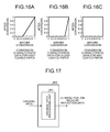
- FIG. 15A is a diagram illustrating a result of inverting the toner total attachment amount T, which is calculated from original data illustrated in FIG. 15B ;
- FIGS. 16A to 16C are diagrams illustrating conversion characteristics (conversion data) used during conversion of inverted data according to the third embodiment
- FIG. 17 is a diagram illustrating a configuration according to a fourth embodiment of the present invention.
- FIG. 18 is a diagram illustrating a warped state of a paper sheet
- FIG. 19 is a diagram illustrating an exemplary cross-shaped key displayed on a display device
- FIG. 20 is a diagram illustrating paper-portion regular reflection application ratio data and image-portion regular reflection application ratio data according to a tenth embodiment
- FIG. 21 is a diagram illustrating an attenuation parameter of the types of paper
- FIG. 22 is a diagram illustrating a parameter rr of types of paper
- FIG. 23 is a diagram illustrating an attenuation parameter of the types of paper.
- FIG. 24 is a diagram illustrating attenuation characteristics
- FIG. 25 is a diagram illustrating a visual evaluation result.
- FIG. 2 is a diagram illustrating a configuration of the information processing device according to the first embodiment.
- a display device 102 is used to display print preview images, print images, and a user interface (UI).
- the display device 102 is a liquid crystal display.
- An input device 101 is used by a user to input instructions and necessary data values.
- the input device 101 according to the first embodiment includes a keyboard and a mouse. However, it is also possible to have other input devices connected as the input device 101 .
- a processing device 104 is configured with a central processing unit (CPU) 105 and a random access memory (RAM) 106 that control the entire image processing device.
- a memory device 103 is used to store computer programs run by the CPU 105 and to store data used by the CPU 105 .
- the processing device 104 runs the computer programs stored in the memory device 103 , processes the data stored in the memory device 103 , and displays the processing result on the display device 102 .
- the texture (the gloss feel) of the printed material is displayed (reproduced) on the display. That is, the printed material preview (or the printed material display) can be performed on a display by means of 3D display.
- an instruction input by the user from the input device 101 has the following contents in concrete terms: 1. the original data of the target printed material for a printed material preview; and 2. the type of paper to be used in printing.
- the printed material is made of a paper sheet and the original data.
- the original data is in the form of a data file having the BMP format.
- the paper sheet is made selectable from three types of paper (namely, the cast-coated paper, the gloss-coated paper, or the mat-coated paper). These three types of paper are the representative types that characterize the textures of printing paper. If the textures of these three types of paper can be displayed (reproduced) in the 3D display preview of a printed material, then it is expected to be comparatively easier to reproduce the various other types of paper.
- the first embodiment although only three types of paper are made selectable, it is perfectly acceptable if other types of paper are also made selectable (i.e., more types of paper are also made selectable).
- the configuration is such that data for previewing is calculated using the following types of data apart from using the original data: (1) paper portion diffuse reflection data; (2) paper portion regular reflection data; (3) paper-portion regular reflection applicable area data; (4) paper-portion regular reflection application ratio data; (5) image portion regular reflection data; (6) image-portion regular reflection applicable area data; and (7) image-portion regular reflection application ratio data.
- the original data indicates data of an image printed on a sheet of paper.
- the type of data (1) (first data in claims) indicates diffuse reflection of the sheet.
- the type of data (2) (fourth data in claims) indicates regular reflection of the sheet.
- the type of data (3) (fifth data in claims) is used for instructing segmentation of an area in which the fourth data is to be applied and an area in which the fourth data is not to be applied.
- the type of data (4) (sixth data in claims) indicates ratios at which the fourth data is applied.
- the type of data (5) (seventh data in claims) indicates regular reflection of the image.
- the type of data (6) is used for instructing segmentation of an area in which the seventh data is to be applied and an area in which the seventh data is not to be applied.
- the type of data (7) indicates ratios at which the seventh data is applied.
- Three types of data (2) to (4) may be collectively referred to as data (second data in claims) used for giving regular reflection texture of the sheet to a display image for displaying texture of the printed material.
- Three types of data (5) to (7) (seventh data to ninth data in claims) may be collectively referred to as data (third data in claims) used for giving regular reflection texture of the image to the display image for displaying the texture of the printed material.
- the data of the types (1) to (7) are created in advance and stored in the memory device 103 . Moreover, in the drawings, the data of the types (1) to (7) are illustrated as circled numbers.
- the paper portion diffuse reflection data is created by taking images of real cast-coated paper (mirror coat platinum paper, Oji Paper Co., Ltd.) using a digital camera. While taking the images; the positioning of the paper sheets, the positioning of the lighting equipment, and the positioning of the image capturing device (the digital camera) was determined in such a way that images of diffuse reflection from the paper surface could be taken. More particularly, the images were taken by setting the angle of incident light from the lighting equipment to the paper sheets to 45° and by setting the position of the image capturing device to 0°.
- the image capturing conditions were adjusted to have a resolution of 400 dpi with respect to the size of the actual paper sheets.
- the brightness of the captured images was adjusted to have the average value of 235 (8 bits) (where “0” represents black and “255” represents white).
- the captured images were smaller in size as compared to the size of the printed material to be previewed (i.e., as compared to the size of the original data), the images were concatenated and expanded to the same size as the size of the printed material.
- the image data generated in this way is used as (1) paper portion diffuse reflection data.
- a diffuse reflection image of a real paper sheet is captured using a digital camera.
- the characteristic that the diffuse reflection changes minutely at each position of the paper surface i.e., the textures sensed in the diffuse reflection on the paper surface
- paper portion diffuse reflection data there is a change in the data value at each position (each pixel).
- Such changes in the data values reflect the characteristic in which the diffuse reflection on the paper surface changes minutely.
- the paper portion regular reflection data is created by capturing images of real cast-coated paper (mirror coat platinum paper, Oji Paper Co., Ltd.) using a digital camera. While capturing the images; the positioning of the paper sheets, the positioning of the lighting equipment, and the positioning of the image capturing device (the digital camera) was determined in such a way that images of regular reflection from the paper surface could be taken. More particularly, the images were taken by setting the angle of incident light from the lighting equipment to the paper sheets to 20° and by setting the position of the image capturing device to 20°.
- the image capturing conditions are adjusted to have a resolution of 400 dpi with respect to the size of the actual paper sheets. Furthermore, since the captured images were dark in nature, the brightness of the captured images was adjusted to have the average value of 253 (8 bits). Moreover, since the captured images are smaller in size as compared to the size of the printed material to be previewed (i.e., as compared to the size of the original data), the images are concatenated and expanded to the same size as the size of the printed material. Then, in the first embodiment, the image data generated in this way is used as (2) paper portion regular reflection data.
- a regular reflection image of a real paper sheet is captured using a digital camera.
- the characteristic that the regular reflection changes minutely at each position of the paper surface i.e., the textures sensed in the regular reflection on the paper surface
- paper portion regular reflection data there is a change in the data value at each position (each pixel).
- Such changes in the data values reflect the characteristics in which the regular reflection on the paper surface changes minutely.
- (1) paper portion diffuse reflection data and (2) paper portion regular reflection data is created also with respect to the gloss-coated paper and the mat-coated paper, and is stored in the memory device 103 . Then, depending on the type of paper selected from the input device 101 , (1) paper portion diffuse reflection data and (2) paper portion regular reflection data corresponding to the selected type of paper is read from the memory device 103 .
- (3) paper-portion regular reflection applicable area data has the role of instructing, with respect to the original data, a segmentation in the form of an area in which the regular reflection of the paper portion is to be applied and an area in which the regular reflection of the paper portion is not to be applied.
- (3) paper-portion regular reflection applicable area data is in the form of a data file having the BMP format.
- (3) paper-portion regular reflection applicable area data has the same size as the size of the original data.
- (3) paper-portion regular reflection applicable area data is also created corresponding to each of the abovementioned three types of paper and is stored in the memory device 103 .
- FIGS. 3A to 3C represent the outlines of sets of (3) paper-portion regular reflection applicable area data according to the first embodiment.
- FIGS. 3A to 3C represent the sets of (3) paper-portion regular reflection applicable area data corresponding to original data illustrated in FIG. 3D .
- shades correspond to the data values of the application ratio of the paper portion regular reflection.
- the white portions correspond to image areas in which the regular reflection of the paper portion is applied (the paper portion regular reflection data has the application ratio of 1.0), while the black portions correspond to image areas in which the regular reflection of the paper portion is not applied (the paper portion regular reflection data has the application ratio of 0.0).
- the original data of FIG. 3D is made of gray data (16 patch images in the upper half) and color data (16 patch images in the lower half).
- (3) paper-portion regular reflection applicable area data is created in such a way that each pixel corresponds to a value between 0.0 and 1.0.
- intermediate values between 0.0 and 1.0 are also used as the values of pixels.
- the area is such that the application ratio is applied as the intermediate value to (2) paper portion regular reflection data (as described later in calculation formulae, the remaining application ratio at that time is compensated from (1) paper portion diffuse reflection data).
- (3) paper-portion regular reflection applicable area data is created in the following manner.
- a real print image is created by forming patch images on a real cast-coated paper sheet (mirror coat platinum paper, Oji Paper Co., Ltd.). Then, while visually confirming the print image, with respect to the area in which the gloss feel of the paper sheet is observed, value setting is done in such a way that the application ratio of the paper portion regular reflection data is 0.0. Moreover, intermediate values are set with respect to an area in which the gloss feel of the paper sheet is observed to be weak.
- (3) paper-portion regular reflection applicable area data is created also with respect to the gloss-coated paper and the mat-coated paper and is stored in the memory device 103 . Then, depending on the type of paper selected from the input device 101 , (3) paper-portion regular reflection applicable area data corresponding to the selected type of paper is read from the memory device 103 .
- (4) paper-portion regular reflection application ratio data is created in such a way that the ratio of applying the regular reflection texture of the paper portion differs according to the position.
- (4) paper-portion regular reflection application ratio data is in the form of a data file having the BMP format.
- (4) paper-portion regular reflection application ratio data is also created corresponding to each of the abovementioned three types of paper and is stored in the memory device 103 .
- FIGS. 4A to 4C represent the outlines of sets of (4) paper-portion regular reflection application ratio data according to the first embodiment.
- shades correspond to the data values of (4) paper-portion regular reflection application ratio data.
- the value of (4) paper-portion regular reflection application ratio data corresponds to 1.0.
- the value of (4) paper-portion regular reflection application ratio data corresponds to 0.0.
- (4) paper-portion regular reflection application ratio data is created in the following manner. Firstly, image data in which only the position of the local maximum value is written is created at the same image size as the image size of application ratio data.
- FIG. 4D indicates the image data in which only the position of the local maximum value is written. A thin white portion in the center corresponds to a position (x 0 , y 0 ) of the local maximum value. Subsequently, with respect to the image data in which only the local maximum value is written (i.e., with respect to FIG. 4D ), a distance r from each pixel (each position) in the black portion to the closest local maximum value is calculated. Using the distances r, the value of (4) paper-portion regular reflection application ratio data of the pixel of interest is calculated using Equation (1) given below.
- parameters a, b, and c are appropriately set parameters.
- the values of the parameters a, b, and c that are used in calculating the data illustrated in FIGS. 4A to 4C are illustrated in FIG. 21 .
- the parameter b is dependent on the image size of (4) paper-portion regular reflection application ratio data. For that reason, in the case of creating (4) paper-portion regular reflection application ratio data having a different image size than the image size according to the first embodiment, it becomes necessary to adjust the value while maintaining the relative relationship.
- the value of the parameter b illustrated in FIG. 21 is the value in the case when 1.0 is set as the length of a side of the image size of (4) paper-portion regular reflection application ratio data.
- (5) image portion regular reflection data has the role of giving a gloss feel (a texture) to the image portion (the toner attachment portion).
- (5) image portion regular reflection data is generated by processing the original data. Equation (2) given below is a calculation formula for calculating (5) image portion regular reflection data according to the first embodiment.
- Data′ Data*(1.0 ⁇ rr )+255 *rr (2)
- “Data” corresponds to each component of RGB values in each pixel in the original data.
- “rr” changes the value for each type of paper.
- the original data is assumed to be 8-bit RGB data, the value 255 corresponding to the white color is used in the second term in Equation (2).
- the rr values used in Equation (2) are as specified in FIG. 22 .
- (6) image-portion regular reflection applicable area data is equivalent to the data when the image portion is the target for (3) paper-portion regular reflection applicable area data.
- (6) image-portion regular reflection applicable area data has the role of instructing a segmentation about the area in which the regular reflection of the image portion is to be applied and the area in which the regular reflection of the image portion is not to be applied.
- (6) image-portion regular reflection applicable area data is in the form of a data file having the BMP format.
- (6) image-portion regular reflection applicable area data has the same data size as the data size of the original data.
- three types of (6) image-portion regular reflection applicable area data corresponding to the abovementioned three types of paper are stored in the memory device 103 .
- FIGS. 5A to 5C represent the outlines of sets of (6) image-portion regular reflection applicable area data according to the first embodiment.
- FIGS. 5A to 5C represent the sets of (6) image-portion regular reflection applicable area data corresponding to original data illustrated in FIG. 5D .
- shades correspond to the data values of the application ratio of the image portion regular reflection.
- the white portions correspond to image areas in which the regular reflection of the image portion is applied (the image portion regular reflection data has the application ratio of 1.0), while the black portions correspond to image areas in which the regular reflection of the image portion is not applied (the image portion regular reflection data has the application ratio of 0.0).
- (6) image-portion regular reflection applicable area data is created in such a way that each pixel corresponds to a value between 0.0 to 1.0.
- intermediate values between 0.0 and 1.0 are also used as the values of pixels.
- the area is such that the application ratio is applied as the intermediate value to (6) image-portion regular reflection applicable area data (as described later in calculation formulae, the remaining application ratio at that time is compensated from (1) paper portion diffuse reflection data).
- (6) image-portion regular reflection applicable area data is created in the following manner.
- a real print image is created by forming patch images on a real cast-coated paper sheet (mirror coat platinum paper, Oji Paper Co., Ltd.).
- value setting is done in such a way that the application ratio of the image portion regular reflection data is 1.0.
- value setting is done in such a way that the application ratio of the image portion regular reflection data is 0.0.
- (6) image-portion regular reflection applicable area data is created also with respect to the gloss-coated paper and the mat-coated paper and is stored in the memory device 103 . Then, depending on the type of paper selected from the input device 101 , (6) image-portion regular reflection applicable area data corresponding to the selected type of paper is read from the memory device 103 .
- image-portion regular reflection application ratio data is similar to (4) paper-portion regular reflection application ratio data explained above. Because of (7) image-portion regular reflection application ratio data, it becomes possible to reproduce the regular reflection part reflecting on the surface of the image portion of the printed material (i.e., the lighting is reflected and becomes visible).
- (7) image-portion regular reflection application ratio data is created in such a way that the ratio of applying the regular reflection texture of the image portion is different according to the position.
- (7) image-portion regular reflection application ratio data is in the form of a data file having the BMP format.
- three types of (7) image-portion regular reflection application ratio data corresponding to the abovementioned three types of paper are stored in the memory device 103 .
- FIGS. 6A to 6C are represent the outlines of sets of (7) image-portion regular reflection application ratio data according to the first embodiment.
- shades correspond to the data values of (7) image-portion regular reflection application ratio data.
- the white portion corresponds to the ratio of 1.0 of the image regular reflection characteristic data, while the black portion corresponds to the ratio of 0.0 of the image-portion regular reflection application ratio data.
- the method of creating (7) image-portion regular reflection application ratio data is identical to the method of creating (4) paper-portion regular reflection application ratio data. Hence, that explanation is not given again.
- the values of the parameters a, b, and c that are used in Equation (1) for calculating the data illustrated in FIGS. 6A to 6C are illustrated in FIG. 23 .
- FIG. 1 is a process flowchart of an image processing method according to an embodiment of the present invention. Firstly, original data and the type of paper are specified from the input device 101 (Step S 1 ).
- each of seven types of data namely, (1) paper portion diffuse reflection data, (2) paper portion regular reflection data, (3) paper-portion regular reflection applicable area data, (4) paper-portion regular reflection application ratio data, (5) image portion regular reflection data, (6) image-portion regular reflection applicable area data, and (7) image-portion regular reflection application ratio data stored in the memory device 103 ; the CPU 105 reads to the RAM 106 the data corresponding to the type of paper specified at Step S 1 (Step S 2 ).
- a placement position S(x, y, z) of each coordinate position of original data a placement position PD(x, y, z) of each coordinate position of (1) paper portion diffuse reflection data; a placement position PS(x, y, z) of each coordinate position of (2) paper portion regular reflection data; a placement position PAA(x, y, z) of each coordinate position of (3) paper-portion regular reflection applicable area data; a placement position IS(x, y, z) of each coordinate position of (5) image portion regular reflection data; and a placement position IAA(x, y, z) of each coordinate position of (6) image-portion regular reflection applicable area data (Step S 3 ) (this operation corresponds to placing the original data and the data required for expressing the texture (the gloss feel) in a virtual three-dimensional space).
- the placement is done in such a way that the center point of the original data matches with the origin of the virtual three-dimensional space. Moreover, except the data of the types (4) and (7) explained above; the data of the types (1) to (7) is placed at the same position of the original data. Furthermore, in the first embodiment, each coordinate position of the original data is placed in such a way that the original data forms a simple plane surface. Accordingly, the placement is done so as to ensure that each coordinate position of the data of the types (1) to (7) (except the data of the types (4) and (7)) is same as the original position.
- the placement is done in such a way that the plane surface on which the original data and the data of the types (1) to (7) (except the data of the types (4) and (7)) has the normal vector oriented in the Z-axis direction (in the first embodiment, the original data and the data of the types (1) to (7) (except the data of the types (4) and (7)) is placed in such a way that, at all coordinate positions, a normal vector n(x, y, z) becomes (0, 0, 1.0).
- Step S 4 a placement position PAR(x, y, z) of (4) paper-portion regular reflection application ratio data and a placement position IAR(x, y, z) of (7) image-portion regular reflection application ratio data are determined (Step S 4 ) (this operation corresponds to determining the position of lighting in the virtual three-dimensional space).
- the placement is such that the center of (4) paper-portion regular reflection application ratio data and the center of (7) image-portion regular reflection application ratio data match at a coordinate point (0, 0, 1.0) in the virtual three-dimensional space.
- FIG. 7 is a diagram illustrating a condition of placement of the original data and the data of (1) to (7), which is processed at Steps S 3 and S 4 , in the virtual three-dimensional space.
- original data 200 (1) paper portion diffuse reflection data 201 ; (2) paper portion regular reflection data 202 ; (3) paper-portion regular reflection applicable area data 203 ; (5) image portion regular reflection data 205 ; and (6) image-portion regular reflection applicable area data 206 is placed in such a way that, at the same position, the center is at an origin O of the virtual three-dimensional space.
- FIG. 8 is a diagram illustrating a condition of placement of the original data and the data of the types (1) to (7) in the virtual three-dimensional space in the case in which the actual original data is used as the original data illustrated in FIG. 7 .
- the coordinate point (0. 0. 1.0) is set to be the viewpoint position.
- a reflection vector r(x, y, z) is calculated (Step S 6 ).
- the reflection vector represents the direction of regular reflection on the face defined by the normal vector with respect to the vector directed from the viewpoint position toward the position of interest in the original data.
- FIG. 9 is illustrated the relationship between the viewpoint position E, an eye vector in the viewpoint direction, the placement position S(x, y, z) of each coordinate position of the original data, the normal vector n(x, y, z), and the reflection vector r(x, y, z).
- a diffuse reflection component of the data for previewing is calculated (Step S 7 ).
- the diffuse reflection component is calculated by normalizing and multiplying the original data and (1) paper portion diffuse reflection data for each placement position (for each pixel) in the virtual three-dimensional space. That is, the value of a diffuse reflection component Cdiff is calculated as given below in Equation (3) from an original data value S and (1) paper portion diffuse reflection data value Pdiff at the same placement position in the three-dimensional space.
- Equation (3) when each set of data is 8-bit data that is normalized and integrated, the value 255 is used to restore the original 8-bit data (if the data is not 8-bit data, the value 255 is changed in an appropriate manner).
- C diff S
- Step S 8 the ratio of applying (2) paper portion regular reflection data is determined.
- This value of application ratio is the integrated value of (3) paper-portion regular reflection applicable area data at each coordinate position of the original data and (4) paper-portion regular reflection application ratio data in the direction indicated by the reflection vector r(x, y, z) that is calculated at each coordinate position of the original data.
- the value of the position of interest in the original data is used.
- the value at such a position is used at which the direction indicated by the reflection vector at the position of interest in the original data intersects with (4) paper-portion regular reflection application ratio data placed in the virtual three-dimensional space. Then, the integrated value of both values serves as the value of the ratio for applying the paper portion regular reflection data at the position of interest in the original data.
- the value of (4) paper-portion regular reflection application ratio data is set to become equal to 0.0.
- Rpa represents the value of the ratio for applying the paper portion regular reflection data at the position of interest in the original data as calculated at Step S 8
- Paa represents the value of (3) paper-portion regular reflection applicable area data at the position of interest in the original data
- Par represents the value of (4) paper-portion regular reflection application ratio data at the position indicated by the reflection vector
- a paper portion regular reflection component in the data for previewing is calculated (Step S 9 ).
- the paper portion regular reflection component is calculated by integrating, for each position of interest (for each pixel) of the original data, the application ratio value calculated at Step S 8 with the RGB values of (2) paper portion regular reflection data.
- the value of a paper regular reflection component CPspe is calculated using Equation (5) given below from the application ratio value Rpa (calculated at Step S 8 ) corresponding to the position of interest in the original data placed in the virtual three-dimensional space and from a data value Pspec of (2) paper portion regular reflection data at the position of interest.
- FIG. 10 is a diagram illustrating the positional relationship (the placement relationship) of a viewpoint position 301 , a position of interest 302 of the original data, the position of (2) paper portion regular reflection data used in calculation, the position of (3) paper-portion regular reflection applicable area data used in calculation, and the position of (4) paper-portion regular reflection application ratio data 304 used in calculation.
- CP spec Rpa ⁇ P spec (5)
- Step S 10 the ratio for applying (5) image portion regular reflection data is determined.
- This value of application ratio is an integrated value of (6) image-portion regular reflection applicable area data at each coordinate position of the original data and (7) image-portion regular reflection application ratio data at the position instructed by a reflection vector r(x, y, z) 303 that is calculated at each coordinate position of the original data.
- image-portion regular reflection applicable area data the value of the position of interest in the original data is used.
- image-portion regular reflection application ratio data the value at such a position is used at which the direction indicated by the reflection vector at the position of interest in the original data intersects with (7) image-portion regular reflection application ratio data placed in the virtual three-dimensional space. Then, the integrated value of both values serves as the value of the ratio for applying the paper portion regular reflection data at the position of interest in the original data.
- the value of (7) image-portion regular reflection application ratio data is set to become equal to 0.0.
- Ria represents the value of the ratio for applying the image portion regular reflection data at the position of interest in the original data as calculated at Step S 10
- Iaa represents the value of (6) image-portion regular reflection applicable area data at the position of interest in the original data
- ifCDC represents the value of (7) image-portion regular reflection application ratio data at the position indicated by the reflection vector; then a calculation formula is as given in Equation (6).
- Ria Iaa ⁇ Iar (6)
- an image portion regular reflection component in the data for previewing is calculated (Step S 11 ).
- the image portion regular reflection component is calculated by integrating, for each position of interest (for each pixel) of the original data, the application ratio value calculated at Step S 10 with the RGB values of (5) image portion regular reflection data.
- Equation (7) the value of an image regular reflection component CIspe is calculated using Equation (7) given below from Ria corresponding to the position of interest in the original data placed in the virtual three-dimensional space and from a data value Ispec of (5) image portion regular reflection data at the position of interest.
- CI spec Ria ⁇ I spec (7)
- the value of the data for previewing at the position of interest in the original data is calculated from the diffuse reflection component Cdiff calculated at Step S 7 , the ratio Rpa for applying the paper portion regular reflection data as calculated at Step S 8 , the paper regular reflection component CPspe calculated at Step S 9 , the ratio Ria for applying the image portion regular reflection data as calculated at Step 10 S 10 , and the image regular reflection component CIspe calculated at Step S 11 .
- the value of the data for previewing is calculated using Equation (8) given below.
- Equation (8) in the data for previewing, as far as the diffuse reflection component Cdiff is concerned, normally the diffuse reflection component Cdiff is replaced with the paper regular reflection component CPspe or the image regular reflection component CIspe in a partial manner (in a portion in which the regular reflection component is to be reflected); the texture (the gloss feel) of the printed material is expressed.
- P Cdiff ⁇ (1.0 ⁇ Rpa ) ⁇ (1.0 ⁇ Ria)+CPspe+CIspe (8)
- the value of the data for previewing as calculated by the operations from Steps S 1 to S 12 is subjected to rendering on a display that serves as the display device 102 .
- the texture the gloss feel
- an “authentic” printed material texture can be reproduced on the display.
- the present invention is not limited to the first embodiment.
- the various parameters illustrated in FIGS. 21 to 23 can have values different than the values illustrated in FIGS. 21 to 23 .
- the color temperature of the lighting is incorporated.
- the same functionality can be implemented in the first embodiment too.
- the necessary data such as the original data, (1) paper portion diffuse reflection data, (2) paper portion regular reflection data, and (5) image portion regular reflection data; an image is calculated in which color conversion is done in accordance with the light color temperature to be reflected, and the post-color-conversion data is used in calculating the data value for a preview image in an identical manner to the manner described above.
- the printed material preview can be done in which the color temperature of the lighting is also incorporated.
- the object of the present invention can be achieved when the method of calculating the data for previewing printed material is implemented in a computer program using a three-dimensional graphics application programming interface (API) such as OpenGL or DirectX.
- API application programming interface
- (4) paper-portion regular reflection application ratio data incorporates the characteristics explained below (although the value of b differs for each type of paper, the relationship given below in Equation (9) is satisfied for each type of paper). That is, if (x 0 , y 0 ) was set to represent the position indicating the local maximum value of (4) paper-portion regular reflection application ratio data, then (4) paper-portion regular reflection application ratio data PR (x, y) had become (4) paper-portion regular reflection application ratio data having the attenuation characteristic expressed in Equation (9).
- the parameters a, b, and c are constant numbers set in an appropriate manner.
- the inventor(s) of the present invention tested other attenuation characteristics too; and studied about the attenuation characteristics that, when a printed material previewing is performed, enable more authentic visual recognition as far as the shape of lighting reflected on the paper sheet is concerned. Given below is the explanation of the study results.
- a printed material preview was performed by changing only (4) paper-portion regular reflection application ratio data.
- a printed material preview image displayed on the display was evaluated by means of visual observation and the evaluation was performed from the perspective of whether or not it is seen to be a more authentic reflection of the shape of lighting.
- the first embodiment is related to the attenuation characteristic given in Equation (9) (the details of the calculation formulae are given in FIG. 24 ).
- a first comparison example is related to an attenuation characteristic in which the multiplier of r in Equation (9) is changed from 2 to 1 (the details of the calculation formulae are given in FIG. 24 ).
- a second comparison is related to an attenuation characteristic in which the multiplier of r in Equation (9) is changed from 2 to 3 (the details of the calculation formulae are given in FIG. 24 ).
- a third comparison example is related to an attenuation characteristic of what is called Gaussian distribution (the details of the calculation formulae are given in FIG. 24 ).
- FIG. 25 The result of visual evaluation is illustrated in FIG. 25 .
- the result indicated that the attenuation characteristic appears to be suitable and the reflection appears to be authentic.
- the visual observation result indicated that the attenuation is either too moderate or steep and the reflection appeared to be somewhat not real.
- an item “ranking” in FIG. 25 indicates the result of ranking the attenuation characteristic from the perspective of whether the reflection appears to be authentic.
- the attenuation characteristic according to the first embodiment enables reproduction of an “authentic” texture of the paper sheet.
- the explanation is given about generating image-portion regular reflection applicable area data from the original data.
- the configuration according to the second embodiment is identical for the most part to the configuration according to the first embodiment.
- the second embodiment differs in the way that, instead of generating image-portion regular reflection applicable area data directly and manually while confirming an image in which (6) image-portion regular reflection applicable area data is actually printed as described in the first embodiment, an image-portion regular-reflection-applicable-area data generating unit is disposed that generates (6) image-portion regular reflection applicable area data from the original data.
- FIG. 11 is a diagram illustrating a configuration of the image-portion regular-reflection-applicable-area data generating unit according to the second embodiment.
- an image-portion regular-reflection-applicable-area data generating unit 400 includes a toner total-attachment-amount calculating unit 401 and a converting unit 402 that converts the toner total-attachment-amount according to conversion data.
- the toner total-attachment-amount calculating unit 401 receives the original data and calculates data values each of which corresponds to the toner total attachment amount for a pixel in the original data.
- the original data is BMP data having 8-bit RGB colors per pixel.
- the toner total-attachment-amount calculating unit 401 converts RGB values into CMYK data values. That is because, the characteristic of regular reflection of an image portion is highly correlated to the total attachment amount of the toner used in image formation. Hence, the RGB values are converted into CMYK data values that are compatible to the total attachment amount of the toner.
- Ct, My, Yt, and Min_cmy are calculated from the RGB values.
- Min(Ct, Mt, Yt) represents the minimum value of the three values specified within the brackets.
- Min_ cmy min( Ct,Mt,Yt ) (10)
- Ct2, Mt2, Yt2, and Kt2 are calculated.
- the calculation corresponds to ink generation (K component generation).
- Tot_cmyk is calculated using Equation (13) given below.
- Tot _ cmyk Ct 2 +Mt 2 +Yt 2 +Kt 2 (13)
- Max_cmyk 2.6 ⁇ 255
- CMYK values are calculated upon performing ink generation and total volume control.
- FIG. 12A is a diagram illustrating T that is equivalent to the toner total attachment amount calculated from the original data illustrated in FIG. 12B , by implementing the abovementioned method.
- the converting unit 402 converts the value of T and generates (6) image-portion regular reflection applicable area data.
- FIGS. 13A to 13C are diagrams illustrating conversion characteristics (conversion data) used during conversion of the toner total attachment amount T according to the second embodiment.
- the conversion data is created in advance and stored so that it can be used by the image-portion regular-reflection-applicable-area data generating unit 400 according to the second embodiment.
- the conversion data is read and used by the converting unit 402 so as to convert the result calculated by the toner total-attachment-amount calculating unit 401 and to generate (6) image-portion regular reflection applicable area data.
- FIGS. 13A to 13C is illustrated the conversion data corresponding to the three types of paper.
- a real print image is created by printing patch images on real cast-coated paper (mirror coat platinum paper, Oji Paper Co., Ltd.).
- a preview is performed with the preview data having the toner total attachment amount T used without modification as (6) image-portion regular reflection applicable area data (i.e., the data illustrated in FIG. 12A is used without modification as (6) image-portion regular reflection applicable area data).
- the configuration is such that the conversion data is created for not only the cast-coated paper but also for the gloss-coated paper and the mat-coated paper in an identical manner, and the conversion data that corresponds to the paper selected in the preview is used.
- the data for previewing is calculated in an identical manner to the first embodiment.
- (6) image-portion regular reflection applicable area data is dependent on the original data.
- (6) image-portion regular reflection applicable area data needs to be generated again.
- the conversion data illustrated in FIGS. 13A to 13C represents the correspondence between the toner total attachment amount and a toner attachment amount range to which the texture of the image portion is applied. For that reason, the same conversion data can be used for different sets of original data.
- the conversion data can be applied without modification even if the original is changed to another original.
- the configuration according to the second embodiment there is an advantage that the user need not perform any new task in response to a change in the original data.
- a third embodiment the explanation is given for a case in which paper-portion regular reflection applicable area data from the original data.
- the configuration according to the third embodiment is identical for the most part to the configuration according to the first embodiment.
- the third embodiment differs in the way that, instead of generating paper-portion regular reflection applicable area data directly and manually while confirming an image in which (3) paper-portion regular reflection applicable area data is actually printed as described in the first embodiment, a paper-portion regular-reflection-applicable-area data generating unit is disposed that generates (3) paper-portion regular reflection applicable area data from the original data.
- FIG. 14 is a diagram illustrating a configuration of the paper-portion regular-reflection-applicable-area data generating unit according to the third embodiment.
- a paper-portion regular-reflection-applicable-area data generating unit 500 includes a toner total-attachment-amount calculating unit 501 , an attachment-amount-data inverting unit 502 , and a converting unit 503 .
- the toner total-attachment-amount calculating unit 501 according to the third embodiment has identical functionality to the functionality of the toner total-attachment-amount calculating unit 401 according to the second embodiment. That is, the toner total-attachment-amount calculating unit 501 receives the original data, calculates the toner total amount T, and sends the toner total amount T to the attachment-amount-data inverting unit 502 .
- the attachment-amount-data inverting unit 502 creates data T′ in which the attachment amount is inverted using the following equation.
- T′ 1.0 ⁇ T (17)
- the attachment amount data T takes values from 0.0 to 1.0.
- the inverted data T′ calculated using Equation (17) represents the data in which the magnitude relationship of the toner total attachment amount is inverted.
- the attachment-amount-data inverting unit 502 sends the inverted data T′ to the converting unit 503 .
- FIG. 15A is a diagram illustrating T′ that is the inverted data of the toner total attachment amount and that is calculated from the original data illustrated in FIG. 15B , by implementing the method described above.
- the converting unit 503 according to the third embodiment has similar functionality to the converting unit 402 according to the second embodiment.
- the converting unit 503 according to the third embodiment converts the value of the inverted data T′ and generates (3) paper-portion regular reflection applicable area data.
- FIGS. 16A to 16C are diagrams illustrating conversion data in which conversion characteristics are written that are used during conversion of the inverted data T′ according to the third embodiment.
- the conversion data is created in advance and stored so that it can be used by the paper-portion regular-reflection-applicable-area data generating unit.
- the conversion data is read and used by the converting unit so as to convert the result calculated by the attachment-amount-data inverting unit 502 and to generate (3) paper-portion regular reflection applicable area data. Meanwhile, regarding the conversion data, it is necessary to have three types corresponding to the three types of paper considered in the first embodiment.
- FIGS. 16A to 16C is illustrated the conversion data corresponding to the three types of paper.
- a real print image is created by printing patch images on real cast-coated paper (mirror coat platinum paper, Oji Paper Co., Ltd.). Then, a preview is performed with the preview data having the inverted data T′ ( FIG. 15A ) used without modification as (3) paper-portion regular reflection applicable area data. Then, while visually confirming the print image and the preview image, with respect to a toner attachment area in which the gloss feel peculiar to the paper portion is conspicuously seen in the real image, a conversion characteristic that enables an increase in the value of T′ is written in the conversion data.
- the configuration is such that the conversion data is created for not only the cast-coated paper but also for the gloss-coated paper and the mat-coated paper in an identical manner, and the conversion data that corresponds to the paper selected in the preview is used.
- the data for previewing is calculated in an identical manner to the first embodiment.
- (3) paper-portion regular reflection applicable area data is dependent on the original data.
- (3) paper-portion regular reflection applicable area data needs to be generated again.
- the abovementioned conversion data represents the correspondence between the toner total attachment amount and a toner attachment amount range to which the texture of the image portion is applied. For that reason, the same conversion data can be used for different sets of original data.
- the conversion data can be applied without modification even if the original is changed to another original.
- a fourth embodiment the explanation is given for a case in which image portion regular reflection data is generated from original data.
- the configuration according to the fourth embodiment is identical for the most part to the configuration according to the first embodiment.
- the fourth embodiment differs in the way that an image-portion regular reflection data generating unit is disposed that automatically generates (5) image portion regular reflection data.
- FIG. 17 is a diagram illustrating a configuration of the image-portion regular reflection data generating unit according to the fourth embodiment.
- an image-portion regular reflection data generating unit 600 according to the fourth embodiment includes an original data processing unit 601 that generates data by processing the original data by implementing the calculation method same as Equation (2) according to the first embodiment. Then, the image-portion regular reflection data generating unit 600 according to the fourth embodiment considers the processed data to be (5) image portion regular reflection data and uses it in calculating the data for previewing.
- the image-portion regular reflection data generating unit 600 generates (5) image portion regular reflection data by applying different parameters to each type of paper. Moreover, the image-portion regular reflection data generating unit 600 converts data into brighter data. For that reason, the regular reflection occurs in the image portion, thereby making it possible to reproduce a condition for bright viewing.
- the explanation is given about a case in which the normal vector changes according to the position of the printed material.
- the configuration according to the fifth embodiment is identical for the most part to the configuration according to the first embodiment.
- the fifth embodiment differs in the way that, during the operation of determining the placement position of the original data and the other data (i.e., at Step S 3 according to the first embodiment), instead of arranging the original data so as to have a constant normal vector as described in the first embodiment, the original data is placed in such a way that the normal vector of the original data differs at each position of the original data.
- Step S 3 the setting is done to ensure that the normal vector has a constant value at each position of the original data.
- n ( x,y,z ) (0,0,1) (18)
- the setting is done in such a way that the normal vector at each position of the original data has the value calculated in the following equation.
- n ⁇ ( x , y , z ) ( - e a ⁇ ⁇ x - e - a ⁇ ⁇ x 2 , 0 , 1 ) / ( ( - e a ⁇ ⁇ x - e - a ⁇ ⁇ x 2 ) 2 + 1 ) 0.5 ( 19 )
- x represents the coordinate in the virtual three-dimensional space indicating the placement position of the original data.
- a parameter a is dependent on the value taken by the coordinate x.
- the coordinate x is set in such a way that the original data is placed exactly at ⁇ 1.0 ⁇ x ⁇ 1.0.
- the parameter a is set to be equal to 0.1.
- the normal vector that is set according to the fifth embodiment is the normal vector of the original surface in the case when the placement position S(x, y, z) of the original data is placed according to the following equation.
- the original surface is placed in a convexly-deformed manner in the downward direction with respect to the z-direction (at that time, the z-coordinate value changes only in the x-direction but not in the y-direction).
- the subsequent operations are performed.
- the operations performed in the fifth embodiment are identical to the operations performed in the first embodiment.
- the value of the data for previewing is calculated and is subjected to rendering on a display that serves as a display device.
- the texture the gloss feel
- the image portion of the printed material can be reproduced, and an “authentic” printed material texture can be reproduced on the display.
- the setting is such that the normal vector at each position of the original data changes according to that position of the original data.
- the regular reflection part of the paper portion and the image portion is displayed to have a complex shape (if the normal vector is same at each position of the original data, then the regular reflection part of the paper portion and the image portion becomes monotonous in shape or changes in a monotonous manner).
- FIG. 18 is a diagram illustrating a warped state of a paper sheet.
- ruled lines are illustrated in order to demonstrate the warped condition of the paper surface, and are not displayed during the actual preview.
- the normal vector at each position of the original data changes in orientation depending on the position of the original data (i.e., the normal vector no more has a uniform orientation).
- a viewpoint position input device is used.
- the configuration according to the seventh embodiment is identical for the most part to the configuration according to the first embodiment.
- the seventh embodiment differs in the way that, in addition to the configuration according to the first embodiment, a viewpoint position input device is disposed that enables varying the position of visual contact (viewpoint).
- a cross-shaped key as illustrated in FIG. 19 is displayed on the display that serves as the display device 102 . If the cross-shaped key is clicked using a mouse that serves as the input device 101 , then it becomes possible to move the viewpoint from side to side and up and down. Moreover, in the seventh embodiment, it is possible to move the viewpoint backward and forward by scrolling the mouse (the operation of the cross-shaped key using the mouse is converted into the x-coordinate and the y-coordinate of the viewpoint position in the virtual three-dimensional space, the scrolling operation is converted into the z-coordinate in the virtual three-dimensional space, and the viewpoint position is determined).
- the data for previewing is calculated with respect to the newly set viewpoint.
- the preview image can be confirmed while varying the viewpoint position for viewing the printed material.
- the present invention is not limited to the abovementioned configuration, and it is possible to implement various modifications. That is, as long as the configuration includes a viewpoint position input device and enables generation of a preview image using the information input from the viewpoint position input device, any type of configuration can be implemented. A number of devices including a viewpoint position input mechanism have already been proposed. Hence, such devices may also be implemented.
- the explanation is given for a case in which an original data position input device is used.
- the configuration according to the eighth embodiment is identical for the most part to the configuration according to the first embodiment.
- the eighth embodiment differs in the way that, in addition to the configuration according to the first embodiment, an original data position input device that enables varying the position of the original data.
- the placement position of the original data in the virtual three-dimensional space is set in such a way that the paper sheet rotates in the horizontal direction (rotates with the y-axis serving as the center of rotation) in response to horizontal movements of the mouse cursor.
- the placement position of the original data in the virtual three-dimensional space is set in such a way that the paper sheet rotates in the vertical direction (rotates with the x-axis serving as the center of rotation) in response to vertical movements of the mouse cursor.
- the data for previewing is calculated with respect to the newly set position of the original data.
- a ninth embodiment the explanation is given for a case in which the position of original data is determined upon reflecting a folding operation.
- the configuration according to the ninth embodiment is identical for the most part to the configuration according to the first embodiment.
- the ninth embodiment differs in the way that, in addition to the configuration according to the first embodiment, an original-data position determining unit is disposed that determines the position of original data upon reflecting a predetermined folding operation.
- the configuration includes a mechanism for determining the position of the original data upon reflecting a predetermined folding operation.
- the position of the original data is set at the placement position S(x, y, z) determined according to Equation (20) given above.
- the configuration is such that determination of the placement position of the original data, calculation of the data for previewing, and performing a preview display on the display is performed in a repeated manner while varying the constant number a specified in Equation (20). That is, the configuration is such that an animation display is performed in which the printed material placement position changes in the virtual three-dimensional space.
- the setting is such that the constant number a performs a reciprocating movement between the range of ⁇ 0.1 to 0.1 at steps of 0.005. This corresponds to a state in which, in the virtual three-dimensional space, the printed material undergoes deformation while repeating being “convex on the upper side” and being “convex on the lower side”.
- the printed material is made of thin paper sheets. Hence, under normal viewing conditions, so many times the paper sheets are viewed in some or the other folded state (while viewing a printed material, it is not only the case that the printed material is kept on a completely flat place for the viewing purpose).
- the folded states are not still but are moving (i.e., moving images are displayed in which the folded states of a paper sheet change) so as to enable achieving expression of the paper texture with an enhanced “authenticity”.
- the present invention is not limited to the abovementioned configuration.
- any other original data placement method other than Equation (20) can also be implemented.
- the placement positions of the original data are presented as folded states other than the plane surface.
- any original data position determining method can be implemented.
- FIG. 20 is a diagram illustrating (4) paper-portion regular reflection application ratio data and (7) image-portion regular reflection application ratio data according to the tenth embodiment.
- the complex shapes illustrated in FIG. 20 are considered to be the abovementioned sets of data; then, during a 3D display preview of printed material, it becomes possible to deal with more complex shapes of lighting reflected on the surface of the printed material.
- the shapes of lighting reflected in the real printed material are complex in nature because of the real lighting conditions.
- using (4) paper-portion regular reflection application ratio data and (7) image-portion regular reflection application ratio data as illustrated in FIG. 20 it becomes possible to reproduce a more “authentic” printed material texture from the perspective of the complexity of the shapes of lighting.
- a printed material is displayed and, as far as the texture (the gloss feel) of the printed material is concerned, a high level of what is called “authenticity” is reproduced during a 3D display preview of the printed material.
- the conventional technology it is not possible to reproduce a phenomenon in which the paper portion (the toner non-attachment portion) and the image portion (the toner attachment portion) have different textures (particularly, have different scopes of lighting that is reflected). For that reason, in the conventional technology, it is not possible to express the “authenticity” of the printed material. Besides, it is necessary to output a sample image and to perform measurement regarding a large number of patch images. Consequently, the LUT that gets created is also a large-scale LUT. As a result, it requires a large calculation load to calculate the value of the data for previewing.
- an image processing device for displaying a printed material includes a calculating unit that calculates display data based on the original data of the printed material, based on paper-portion diffuse reflection data, based on data that gives the texture of the paper-portion regular reflection of the printed material, and based on data that gives the texture of the image-portion regular reflection of the printed material.
- the image processing device makes use of (1) paper portion diffuse reflection data; (2) paper portion regular reflection data; (3) paper-portion regular reflection applicable area data; (4) paper-portion regular reflection application ratio data; (5) image portion regular reflection data; (6) image-portion regular reflection applicable area data; and (7) image-portion regular reflection application ratio data.
- the image processing device includes a preview data calculating unit that calculates the value of the data for previewing from the abovementioned sets of data.
- (2) paper portion regular reflection data is incorporated according to the application ratio determined from (3) paper-portion regular reflection applicable area data and (4) paper-portion regular reflection application ratio data; and a regular reflection part (reflection of lighting) is formed in the paper portion (the portion in which the toner is not attached).
- (5) image portion regular reflection data is reflected according to the application ratio determined from (6) image-portion regular reflection applicable area data and (7) image-portion regular reflection application ratio data; and a regular reflection part (reflection of lighting) having a different state than in the paper portion is formed in the image portion (the portion in which the toner is attached).
- the image processing device because of the abovementioned configuration, while calculating the data for previewing, also regarding the calculation of the data for previewing in the regular reflection part (reflection of lighting) in the paper portion and the regular reflection part (reflection of lighting) in the image portion, there is no need to access a large-scale LUT (a color-by-color LUT that is three-dimensional data) and the determination can be done by a comparatively simpler data access. Hence, it becomes possible reduce the processing load required in the calculation of the data for previewing.
- a reflected light spread LUT is referred to and a reflected light spread parameter (n) is determined corresponding to the colors of the pixels of interest.
- the reflected light LUT covers all the colors, it becomes an enormous three-dimensional LUT.
- the specular colors are calculated according to a predetermined calculation formula. Then, in the conventional technology, after the specular colors are obtained, compression of the specular colors and calculation of the maximum value of the specular colors is performed followed by determination of the synthesis ratio between the specular colors and the diffuse reflection colors.
- the method requires a large calculation load for calculating the data for previewing and requires a large processing load.
- the image processing device As compared to the conventional technology, in the image processing device according to the present invention, only a small calculation load is required till the calculation of the data for previewing.
- a data access to a large-scale LUT is not required thereby enabling to implement a calculation method having a small calculation load. For that reason, during a 3D display preview of printed material, it becomes possible to perform the preview in which the texture of the printed material is successfully reproduced with only a small calculation load.
- the image-portion regular-reflection-applicable-area data generating unit is disposed that generates (6) image-portion regular reflection applicable area data from the original data.
- the scope of lighting the extent of blurring of lighting
- the extent of blurring of lighting the extent of blurring of lighting
- the paper portion and the image portion have different textures (gloss feels). For that reason, during a preview of the printed material, in order to reproduce the “authenticity” in an enhanced manner, it is necessary to reproduce the texture (the gloss feel) of the paper portion differently from the texture (the gloss feel) of the image portion.
- the configuration is such that the image-portion regular-reflection-applicable-area data generating unit is disposed that generates (6) image-portion regular reflection applicable area data from the original data.
- (6) image-portion regular reflection applicable area data is used for defining the area to which the characteristics of the image portion regular reflection are to be given. Hence, every time there is a change in the original data, it becomes necessary to prepare data suitable for the original data. However, it is a great burden for the user to directly create (6) image-portion regular reflection applicable area data.
- the user only specifies the original data; and (6) image-portion regular reflection applicable area data that is required is generated in the image processing device. Then, (6) image-portion regular reflection applicable area data can be used in calculating the value of the data for previewing.
- the configuration is such that the paper-portion regular-reflection-applicable-area data generating unit is disposed that generates (3) paper-portion regular reflection applicable area data from the original data.
- the user need not perform the task of preparing (3) paper-portion regular reflection applicable area data.
- the user only specifies the original data; and (3) paper-portion regular reflection applicable area data is generated in the image processing device. Then, (3) paper-portion regular reflection applicable area data can be used in calculating the value of the data for previewing.
- the configuration is such that the image-portion regular reflection data generating unit is disposed that generates (5) image portion regular reflection data from the original data.
- the user need not perform the task of preparing (5) image portion regular reflection data.
- the user only specifies the original data; and (5) image portion regular reflection data is generated from the original data in the image processing device. Then, (5) image portion regular reflection data can be used in calculating the value of the data for previewing.
- image portion regular reflection data is required in order to reproduce the gloss feel of the image portion (the toner attachment portion).
- the image portion (the toner attachment portion) changes depending on the original data, it becomes necessary to prepare the image portion regular reflection data for each set of original data (i.e., the image portion regular reflection data changes dependent on the original data).
- the image portion regular reflection data changes dependent on the original data.
- the configuration is such that from the original data can be generated the image portion regular reflection data that is required in order to reflect and reproduce the gloss feel peculiar to the image portion (the toner attachment portion), that is, the gloss feel different than the paper portion (the toner non-attachment portion), in the preview.
- the user is spared from having to perform the cumbersome task of creating the image portion regular reflection data.
- the image-portion regular-reflection-applicable-area data generating unit converts the original data into toner attachment amount data and then generates (6) image-portion regular reflection applicable area data from the toner attachment amount data.
- (6) image-portion regular reflection applicable area data has the function of specifying the area to which the gloss feel (texture) of the image portion is to be applied in a printed material preview.
- the image portion in a printed material has a different gloss feel for each color.
- the gloss feel has a substantial correlation with the toner total attachment amount (the total of the toners of all used colors).
- the gloss feel at the position of interest can be estimated from the toner total attachment amount at that position.
- the amount of toner is a small amount, then there is a strong effect of the surface texture of the paper sheet. On the other hand, if the amount of toner is a large amount, then there is a strong effect of the surface texture of the toner itself. If the amount of toner is an intermediate amount, not only there is an effect of the surface texture of the paper sheet and the surface texture of the toner itself but there is also an effect of the toner placement state. At that time, since the gloss feel of the image portion is determined depending on the various characteristics of the paper sheet and the toner, it is not always true that the gloss feel changes in a monotonous manner depending on the toner attachment amount.
- the gloss feel gets determined in an almost unambiguous manner.
- the gloss feel of the image remains approximately the same.
- toner total attachment amount data (the total of all colors) is calculated and the image-portion regular reflection applicable area data is generated with the toner total attachment amount data serving as the reference of the gloss feel, it becomes possible to generate preview data in which the image portion has a suitable gloss feel given thereto.
- the original data is generally made of color data of the RGB colors.
- the user creates (6) image-portion regular reflection applicable area data while visually confirming the real printed material, he or she specifies the value of the image-portion regular reflection applicable area data with respect to each color (three-dimensional data).
- three-dimensional data considering the complexity and complexity of the workload, it is not practical to manually perform three-dimensional data matching.
- the paper-portion regular-reflection-applicable-area data generating unit once converts the original data into the toner total attachment amount data and then generates (3) paper-portion regular reflection applicable area data from the toner attachment amount data.
- (3) paper-portion regular reflection applicable area data has the function of specifying the area to which the texture (the gloss feel) of the paper portion is to be applied in a printed material preview.
- the image portion in the printed material (the portion in which the toner attachment amount is reflected in small amount and the gloss feel of the paper sheet is reflected in a substantial amount) has a different gloss feel for each color.
- the gloss feel has a substantial correlation with the toner total attachment amount (the total of toners of the used colors).
- the gloss feel at the position of interest can be estimated from the toner total attachment amount at that position.
- the reason is as described above. Such a phenomenon comes into existence also at a location of interest of the present invention at which the toner attachment amount is small and the gloss feel of the paper sheet has a large contribution. Moreover, in the present invention too, the fact that the toner characteristics are determined so as to have the same gloss feel for the toner of each of CMYK colors is assumed to hold true to a number of printed materials. For that reason, all color toners have the same gloss feel, and it is possible to estimate the gloss feel from the toner total attachment amount that is the total of toners of all colors.
- the toner total attachment amount data (the total of all colors)
- paper-portion regular reflection applicable area data is generated with the toner total attachment amount data serving as the reference of the gloss feel; it becomes possible to generate preview data in which, with respect to the image portion in which the toner attachment amount is small and the effect of the paper gloss is strong, a suitable gloss feel is given.
- the original data is generally made of color data of the RGB colors.
- the user creates (3) paper-portion regular reflection applicable area data while visually confirming the real printed material, he or she specifies the value of (3) paper-portion regular reflection applicable area data with respect to each color (three-dimensional data).
- three-dimensional data considering the complexity and complexity of the workload, it is not practical to manually perform three-dimensional data matching.
- paper-portion regular reflection application ratio data and (7) image-portion regular reflection application ratio data are sets of data that differ depending on the position.
- the scope of lighting (the extent of blurring of lighting) reflected in the paper portion (the toner non-attachment portion) is same as the scope of lighting (the extent of blurring of lighting) reflected in the image portion (the toner attachment portion) mainly because only a single set of lighting data is used in calculating the data for previewing. That is, in the conventional technology, the paper portion and the image portion cannot be given different gloss feels (textures).
- the configuration is such that (4) paper-portion regular reflection application ratio data and (7) image-portion regular reflection application ratio data are sets of data which differ depending on the position.
- the gloss feel of the printed material can be expressed while having different scopes of lighting reflected in the paper portion and the image portion.
- the degrees of gloss can be expressed in a 3D display preview.
- the paper portion and the image portion can be given different textures (gloss feels).
- a preview can be performed with an enhanced “authenticity” with respect to the real printed material.
- the configuration is such that (4) paper-portion regular reflection application ratio data and (7) image-portion regular reflection application ratio data are sets of regular reflection application ratio data that have a different regular reflection application ratio data value depending on the position and that satisfy Equation (9).
- Equation (9) indicates that, farther from the position at which the application ratio data becomes equal to the local maximum, the two sets of regular reflection application ratio data become smaller as a function of the square of the distance from the local maximum value.
- the position at which the two sets of regular reflection application ratio data are equal to the local maximum corresponds to the position at the center of lighting. For that reason, using the two sets of regular reflection application ratio data having the characteristics indicated in Equation (9), the manner of attenuation from the center of lighting to the surrounding portion in the reflection of lighting on the real paper sheet can be reflected in an appropriate manner.
- a normal vector determining unit is disposed that determines the normal vector at the position of the original data in such a way that the normal vector at the surface position of the original data changes according to the surface position of the original data.
- the regular reflection part of the paper portion and the regular reflection part of the image portion form a complex shape and appear on the printed material display.
- the printed material itself does not have a particularly high degree of stiffness.
- the printed material is not completely planar in nature. Rather, it is not an exaggeration to say that oftentimes the printed material is viewed in a non-planar state thereof.
- one more aspect is that, when the reflection of lighting on the printed material surface is complex in shape, the preview of the printed material feels normal.
- the setting is such that the normal vector at the position of the original data changes according to the surface position of the original data.
- the paper portion regular reflection area and the image portion regular reflection area that are reflected on the printed material surface can be complex in shape or can change in a complex manner (if the normal vector is same at each position of the original data, then the paper portion regular reflection area and the image portion regular reflection area are monotonous in shape or change in a monotonous manner).
- the visual contact position input device is disposed that enables changing the position of visual contact (visual confirmation).
- the visual contact position input device since the visual contact position input device is disposed that enables changing the position of visual contact, it becomes possible to reproduce a state in which the printed material is viewed from the position of visual contact desired by the user and to display the reproduced state in the 3D display preview. As a result, the user becomes able to confirm the texture (the gloss feel) of the printed material from various positions of visual contact. That is helpful in confirming the three-dimensional texture of the printed material which is the original texture.
- the printed material position input device is disposed that enables changing the printed material position.
- the printed material position input device is disposed that enables changing the printed material position, it becomes possible to reproduce a state in which the printed material is placed at the position desired by the user and to display the reproduced state in a 3D display preview. As a result, the user becomes able to confirm the reflected light from the printed material at various placement positions. That is helpful in confirming the three-dimensional texture of the printed material which is the original texture.
- a printed material position determining unit is disposed that determines the position of the printed material upon reflecting a predetermined folding operation.
- the folded state of the printed material paper
- the folded state is also important. Because of the combination of the paper portion regular reflection/image portion regular reflection of the printed material and the non-planar folded state of the printed material, there is an enhancement in the “authenticity” of the printed material in the 3D display preview.
- the folded state is not still but changing/moving (i.e., moving images are displayed in which the folded states of a paper sheet change), it becomes possible to express the paper texture with an enhanced “authenticity”.
- the printed material position determining unit is disposed that determines the position of the printed material upon reflecting a predetermined folding operation.
- the positions of the printed material can be displayed as moving images in which the folded states of the printed material change. As a result, it becomes possible to express the paper texture with an enhanced “authenticity”.
- a technology that, at the time of displaying the texture and the gloss feel of a printed material (the texture and the gloss feel of an entire printed material including the paper sheet and the toner attachment portion) on a display, contributes in enhancing the reproducibility of the texture (the gloss feel).
- the texture (the gloss feel) of the paper portion and the texture (the gloss feel) of the image portion there is provided a method by which the paper portion and the image portion have different textures (gloss feels), particularly have the reflection of different scopes of lighting, so that the authenticity of the real printed material can be reproduced in a 3D display preview.
- a method for reproducing the texture in a printed material preview by which the following issues arising in the conventional technology are resolved: an enormous number of man-hours are required for creating/accessing a look up table (LUT); and a large calculation load is required as far as real-time processing is concerned.
- a method for reproducing the printed material texture by which there is no occurrence of an issue of having to obtain an enormous volume of data while creating the parameter (n) indicating the degree of diffusion of the gloss or an issue of facing an increase in the calculation load while calculating the value of data for preview display.
- a method for reproducing the paper texture is proposed by which only a small calculation load is required to calculate the value of data for preview display and there is no occurrence of the issue of requiring to toil a lot to deal with an output image formed on a new paper sheet.
Landscapes
- Engineering & Computer Science (AREA)
- Multimedia (AREA)
- Signal Processing (AREA)
- Theoretical Computer Science (AREA)
- Human Computer Interaction (AREA)
- Physics & Mathematics (AREA)
- General Engineering & Computer Science (AREA)
- General Physics & Mathematics (AREA)
- Quality & Reliability (AREA)
- Image Processing (AREA)
- Image Generation (AREA)
- Controls And Circuits For Display Device (AREA)
Abstract
Description
Data′=Data*(1.0−rr)+255*rr (2)
Cdiff=S|255×Pdiff/255*255 (3)
Rpa=Paa×Par (4)
CPspec=Rpa×Pspec (5)
Ria=Iaa×Iar (6)
CIspec=Ria×Ispec (7)
P=Cdiff×(1.0−Rpa)×(1.0−Ria)+CPspe+CIspe (8)
Herein, the parameters a, b, and c are constant numbers set in an appropriate manner.
Ct=255−R
Mt=255−G
Yt=255−B
Min_cmy=min(Ct,Mt,Yt) (10)
Tot_cmyk=Ct2+Mt2+Yt2+Kt2 (13)
r=Max_cmyk−Kt2/Tot_cmyk−Kt2 (14)
C=Ct2*r
M=Mt2*r
Y=Yt2*r
K=Kt2 (15)
T=(C+M+Y+K)/Max_cmyk (16)
T′=1.0−T (17)
n(x,y,z)=(0,0,1) (18)
Claims (14)
Applications Claiming Priority (2)
| Application Number | Priority Date | Filing Date | Title |
|---|---|---|---|
| JP2013-071275 | 2013-03-29 | ||
| JP2013071275A JP6149460B2 (en) | 2013-03-29 | 2013-03-29 | Image processing apparatus and image processing method |
Publications (2)
| Publication Number | Publication Date |
|---|---|
| US20140293341A1 US20140293341A1 (en) | 2014-10-02 |
| US9323490B2 true US9323490B2 (en) | 2016-04-26 |
Family
ID=50389831
Family Applications (1)
| Application Number | Title | Priority Date | Filing Date |
|---|---|---|---|
| US14/226,054 Expired - Fee Related US9323490B2 (en) | 2013-03-29 | 2014-03-26 | Image processing apparatus and image processing method |
Country Status (3)
| Country | Link |
|---|---|
| US (1) | US9323490B2 (en) |
| EP (1) | EP2785042A1 (en) |
| JP (1) | JP6149460B2 (en) |
Cited By (2)
| Publication number | Priority date | Publication date | Assignee | Title |
|---|---|---|---|---|
| US10129437B2 (en) | 2014-08-25 | 2018-11-13 | Ricoh Company, Ltd. | Image processing apparatus, image processing method, recording medium, and program |
| US12205330B2 (en) | 2022-03-25 | 2025-01-21 | Fujifilm Business Innovation Corp. | Non-transitory computer readable medium storing program, information processing apparatus, and information processing method |
Families Citing this family (10)
| Publication number | Priority date | Publication date | Assignee | Title |
|---|---|---|---|---|
| US9911395B1 (en) * | 2014-12-23 | 2018-03-06 | Amazon Technologies, Inc. | Glare correction via pixel processing |
| JP2017010143A (en) * | 2015-06-18 | 2017-01-12 | セイコーエプソン株式会社 | Image processing device |
| JP6452574B2 (en) * | 2015-08-07 | 2019-01-16 | キヤノン株式会社 | Display control apparatus, display control method, and program |
| US10003713B2 (en) * | 2016-04-06 | 2018-06-19 | Kabushiki Kaisha Toshiba | Image forming method and image forming apparatus comprising a scanner section and a light reflection area determination section |
| JP6732541B2 (en) * | 2016-05-30 | 2020-07-29 | キヤノン株式会社 | Image processing apparatus and image processing method |
| JP2019082829A (en) * | 2017-10-30 | 2019-05-30 | 富士ゼロックス株式会社 | Information processing apparatus and information processing program |
| JP2019086129A (en) * | 2017-11-09 | 2019-06-06 | 三菱重工業株式会社 | Sealing method, assembly and method for manufacturing assembly |
| JP7508808B2 (en) * | 2020-03-02 | 2024-07-02 | Toppanホールディングス株式会社 | Display device and method for manufacturing the same |
| JP7698503B2 (en) * | 2021-07-30 | 2025-06-25 | キヤノン株式会社 | Image processing device, method and program |
| JP2024057289A (en) | 2022-10-12 | 2024-04-24 | セイコーエプソン株式会社 | Image processing device, printing system, and image processing program |
Citations (15)
| Publication number | Priority date | Publication date | Assignee | Title |
|---|---|---|---|---|
| US20050219628A1 (en) | 2003-12-02 | 2005-10-06 | Kei Yasutomi | Dither matrix producing method and apparatus, image processing method and apparatus, image forming method and apparatus, program and recording medium |
| US20060066910A1 (en) | 2004-09-30 | 2006-03-30 | Kei Yasutomi | Image forming apparatus, image forming method, and recording medium |
| US20060187505A1 (en) * | 2005-02-22 | 2006-08-24 | Ng Yee S | Profile creation for texture simulation with clear toner |
| US20060279589A1 (en) | 2005-06-08 | 2006-12-14 | Kei Yasutomi | Image processing apparatus and image forming apparatus |
| US20070070470A1 (en) | 2005-09-15 | 2007-03-29 | Junichi Takami | Image processing apparatus and computer program product |
| US20070103730A1 (en) | 2005-11-09 | 2007-05-10 | Kei Yasutomi | Image forming apparatus and image forming method |
| JP2009130461A (en) | 2007-11-20 | 2009-06-11 | Canon Inc | Image processing apparatus and image processing method |
| US20090154827A1 (en) * | 2007-12-14 | 2009-06-18 | Canon Kabushiki Kaisha | Image processing apparatus and method |
| JP2010152533A (en) | 2008-12-24 | 2010-07-08 | Seiko Epson Corp | Texture information data acquisition device and display control system equipped with the same |
| JP2010246049A (en) | 2009-04-09 | 2010-10-28 | Canon Inc | Color processing method, color processing apparatus, and program |
| US20110007333A1 (en) | 2009-07-13 | 2011-01-13 | Canon Kabushiki Kaisha | Color processing apparatus, and method therefor |
| US20110222125A1 (en) | 2010-03-09 | 2011-09-15 | Ricoh Company, Limited | Pseudo-halftoning device, image forming apparatus, and image forming system |
| US8107141B2 (en) * | 2006-03-07 | 2012-01-31 | Canon Information Systems Research Australia Pty. Ltd. | Print presentation |
| JP2012044421A (en) | 2010-08-18 | 2012-03-01 | Canon Inc | Image processing device and image processing method |
| JP2013014299A (en) | 2011-07-06 | 2013-01-24 | Nippon Lock:Kk | Headlight dimming device for motorcycle |
Family Cites Families (5)
| Publication number | Priority date | Publication date | Assignee | Title |
|---|---|---|---|---|
| JP3824674B2 (en) * | 1995-02-03 | 2006-09-20 | 富士写真フイルム株式会社 | Printing proof creation method and apparatus |
| JP5033049B2 (en) * | 2008-04-30 | 2012-09-26 | キヤノン株式会社 | Image processing method and image processing apparatus |
| JP2011175060A (en) * | 2010-02-24 | 2011-09-08 | Ricoh Co Ltd | Image forming apparatus |
| JP5635810B2 (en) * | 2010-05-27 | 2014-12-03 | キヤノン株式会社 | Image processing apparatus and method |
| JP5636885B2 (en) * | 2010-11-08 | 2014-12-10 | 株式会社リコー | Image processing apparatus, image forming apparatus, and image processing system |
-
2013
- 2013-03-29 JP JP2013071275A patent/JP6149460B2/en not_active Expired - Fee Related
-
2014
- 2014-03-25 EP EP14161536.9A patent/EP2785042A1/en not_active Withdrawn
- 2014-03-26 US US14/226,054 patent/US9323490B2/en not_active Expired - Fee Related
Patent Citations (17)
| Publication number | Priority date | Publication date | Assignee | Title |
|---|---|---|---|---|
| US20050219628A1 (en) | 2003-12-02 | 2005-10-06 | Kei Yasutomi | Dither matrix producing method and apparatus, image processing method and apparatus, image forming method and apparatus, program and recording medium |
| US20060066910A1 (en) | 2004-09-30 | 2006-03-30 | Kei Yasutomi | Image forming apparatus, image forming method, and recording medium |
| US20060187505A1 (en) * | 2005-02-22 | 2006-08-24 | Ng Yee S | Profile creation for texture simulation with clear toner |
| US20060279589A1 (en) | 2005-06-08 | 2006-12-14 | Kei Yasutomi | Image processing apparatus and image forming apparatus |
| US20070070470A1 (en) | 2005-09-15 | 2007-03-29 | Junichi Takami | Image processing apparatus and computer program product |
| JP2007110676A (en) | 2005-09-15 | 2007-04-26 | Ricoh Co Ltd | Image processing apparatus and program |
| US20070103730A1 (en) | 2005-11-09 | 2007-05-10 | Kei Yasutomi | Image forming apparatus and image forming method |
| US8107141B2 (en) * | 2006-03-07 | 2012-01-31 | Canon Information Systems Research Australia Pty. Ltd. | Print presentation |
| JP2009130461A (en) | 2007-11-20 | 2009-06-11 | Canon Inc | Image processing apparatus and image processing method |
| US20090154827A1 (en) * | 2007-12-14 | 2009-06-18 | Canon Kabushiki Kaisha | Image processing apparatus and method |
| JP2010152533A (en) | 2008-12-24 | 2010-07-08 | Seiko Epson Corp | Texture information data acquisition device and display control system equipped with the same |
| JP2010246049A (en) | 2009-04-09 | 2010-10-28 | Canon Inc | Color processing method, color processing apparatus, and program |
| US20110007333A1 (en) | 2009-07-13 | 2011-01-13 | Canon Kabushiki Kaisha | Color processing apparatus, and method therefor |
| JP2011023834A (en) | 2009-07-13 | 2011-02-03 | Canon Inc | Color processing method, color processing apparatus, and program |
| US20110222125A1 (en) | 2010-03-09 | 2011-09-15 | Ricoh Company, Limited | Pseudo-halftoning device, image forming apparatus, and image forming system |
| JP2012044421A (en) | 2010-08-18 | 2012-03-01 | Canon Inc | Image processing device and image processing method |
| JP2013014299A (en) | 2011-07-06 | 2013-01-24 | Nippon Lock:Kk | Headlight dimming device for motorcycle |
Non-Patent Citations (3)
| Title |
|---|
| Darling, Benjamin A. and James A. Ferwerda. "Tangible display systems: direct interfaces for computer-based studies of surface appearance." Proceedings of SPIE, vol. 7527 (2010): 75270Q-1-12. |
| Extended European Search Report dated Jul. 8, 2014 issued in corresponding European Application No. 14161536.9. |
| Patil, Rohit A. et al. "3D Simulation of Prints for Improved Soft Proofing." Proceedings of the Color Imaging Conference: Color Science and Engineering Systems, Technologies, Applications (2004): 193-199. |
Cited By (2)
| Publication number | Priority date | Publication date | Assignee | Title |
|---|---|---|---|---|
| US10129437B2 (en) | 2014-08-25 | 2018-11-13 | Ricoh Company, Ltd. | Image processing apparatus, image processing method, recording medium, and program |
| US12205330B2 (en) | 2022-03-25 | 2025-01-21 | Fujifilm Business Innovation Corp. | Non-transitory computer readable medium storing program, information processing apparatus, and information processing method |
Also Published As
| Publication number | Publication date |
|---|---|
| JP6149460B2 (en) | 2017-06-21 |
| EP2785042A1 (en) | 2014-10-01 |
| JP2014194713A (en) | 2014-10-09 |
| US20140293341A1 (en) | 2014-10-02 |
Similar Documents
| Publication | Publication Date | Title |
|---|---|---|
| US9323490B2 (en) | Image processing apparatus and image processing method | |
| JP5195306B2 (en) | Material information data acquisition device and display control system including the same | |
| JP5615041B2 (en) | Image processing apparatus and image processing method | |
| US20140125659A1 (en) | Display processing apparatus, display processing method, and computer program product | |
| JP5272718B2 (en) | Texture information data acquisition device, display control system including the same, texture information data acquisition method, and computer program | |
| US20120032973A1 (en) | Image processing apparatus, image processing method, and storage medium | |
| US8681377B2 (en) | Image processing apparatus, image processing method, and program for executing printing using transparent recording material | |
| JP2003256865A (en) | Method and program for generating 2D image of cartoon expression from 3D object data | |
| JP6028527B2 (en) | Display processing apparatus, display processing method, and program | |
| US12020094B2 (en) | Image processing device, printing system, and non-transitory computer-readable storage medium storing image processing program that render three dimensional (3D) object | |
| US12321648B2 (en) | Image processing device for previewing image to be printed on 3D object | |
| US20110292070A1 (en) | Image processing apparatus and image processing method | |
| JP6708862B1 (en) | Image processing method, program, and image processing apparatus | |
| JP6051890B2 (en) | Image processing apparatus, image processing method, image display method, and program | |
| JP7409014B2 (en) | display device | |
| US20240126484A1 (en) | Image processing apparatus, printing system, and non-transitory computer-readable storage medium storing image processing program | |
| US20240135636A1 (en) | Image processing device, printing system, and non-transitory computer-readable storage medium | |
| JP3327199B2 (en) | How to change the color of an object image | |
| JP2006031595A (en) | Image processing device | |
| Patil et al. | 3D simulation of prints for improved soft proofing | |
| CN116075859B (en) | Generating a target texture from a plurality of source textures | |
| Ferwerda | ImpastoR: A realistic surface display system | |
| JP2024110096A (en) | Image processing device, printing system, and image processing program | |
| JP2024110097A (en) | Image processing device, printing system, and image processing program | |
| JP2024090749A (en) | Image processing device, printing system, and image processing program |
Legal Events
| Date | Code | Title | Description |
|---|---|---|---|
| AS | Assignment |
Owner name: RICOH COMPANY, LIMITED, JAPAN Free format text: ASSIGNMENT OF ASSIGNORS INTEREST;ASSIGNOR:YASUTOMI, KEI;REEL/FRAME:032532/0404 Effective date: 20140324 |
|
| STCF | Information on status: patent grant |
Free format text: PATENTED CASE |
|
| FEPP | Fee payment procedure |
Free format text: MAINTENANCE FEE REMINDER MAILED (ORIGINAL EVENT CODE: REM.); ENTITY STATUS OF PATENT OWNER: LARGE ENTITY |
|
| LAPS | Lapse for failure to pay maintenance fees |
Free format text: PATENT EXPIRED FOR FAILURE TO PAY MAINTENANCE FEES (ORIGINAL EVENT CODE: EXP.); ENTITY STATUS OF PATENT OWNER: LARGE ENTITY |
|
| STCH | Information on status: patent discontinuation |
Free format text: PATENT EXPIRED DUE TO NONPAYMENT OF MAINTENANCE FEES UNDER 37 CFR 1.362 |
|
| FP | Lapsed due to failure to pay maintenance fee |
Effective date: 20200426 |