US9319988B1 - Method and system for determining initial transmission power - Google Patents
Method and system for determining initial transmission power Download PDFInfo
- Publication number
- US9319988B1 US9319988B1 US14/209,591 US201414209591A US9319988B1 US 9319988 B1 US9319988 B1 US 9319988B1 US 201414209591 A US201414209591 A US 201414209591A US 9319988 B1 US9319988 B1 US 9319988B1
- Authority
- US
- United States
- Prior art keywords
- base station
- transmit power
- geographic location
- carrier frequency
- baseline
- Prior art date
- Legal status (The legal status is an assumption and is not a legal conclusion. Google has not performed a legal analysis and makes no representation as to the accuracy of the status listed.)
- Active, expires
Links
Images


Classifications
-
- H—ELECTRICITY
- H04—ELECTRIC COMMUNICATION TECHNIQUE
- H04W—WIRELESS COMMUNICATION NETWORKS
- H04W52/00—Power management, e.g. Transmission Power Control [TPC] or power classes
- H04W52/04—Transmission power control [TPC]
- H04W52/18—TPC being performed according to specific parameters
- H04W52/28—TPC being performed according to specific parameters using user profile, e.g. mobile speed, priority or network state, e.g. standby, idle or non-transmission
- H04W52/283—Power depending on the position of the mobile
-
- H—ELECTRICITY
- H04—ELECTRIC COMMUNICATION TECHNIQUE
- H04W—WIRELESS COMMUNICATION NETWORKS
- H04W52/00—Power management, e.g. Transmission Power Control [TPC] or power classes
- H04W52/04—Transmission power control [TPC]
-
- H—ELECTRICITY
- H04—ELECTRIC COMMUNICATION TECHNIQUE
- H04W—WIRELESS COMMUNICATION NETWORKS
- H04W52/00—Power management, e.g. Transmission Power Control [TPC] or power classes
- H04W52/04—Transmission power control [TPC]
- H04W52/38—TPC being performed in particular situations
-
- H—ELECTRICITY
- H04—ELECTRIC COMMUNICATION TECHNIQUE
- H04W—WIRELESS COMMUNICATION NETWORKS
- H04W52/00—Power management, e.g. Transmission Power Control [TPC] or power classes
- H04W52/04—Transmission power control [TPC]
- H04W52/06—TPC algorithms
- H04W52/14—Separate analysis of uplink or downlink
- H04W52/143—Downlink power control
-
- H—ELECTRICITY
- H04—ELECTRIC COMMUNICATION TECHNIQUE
- H04W—WIRELESS COMMUNICATION NETWORKS
- H04W52/00—Power management, e.g. Transmission Power Control [TPC] or power classes
- H04W52/04—Transmission power control [TPC]
- H04W52/38—TPC being performed in particular situations
- H04W52/40—TPC being performed in particular situations during macro-diversity or soft handoff
-
- H—ELECTRICITY
- H04—ELECTRIC COMMUNICATION TECHNIQUE
- H04W—WIRELESS COMMUNICATION NETWORKS
- H04W52/00—Power management, e.g. Transmission Power Control [TPC] or power classes
- H04W52/04—Transmission power control [TPC]
- H04W52/38—TPC being performed in particular situations
- H04W52/50—TPC being performed in particular situations at the moment of starting communication in a multiple access environment
Definitions
- a wireless service provider typically operates a radio access network (RAN) that includes a number of base stations that radiate to define wireless coverage areas, such as cells and cell sectors, in which user equipment devices (UEs) such as cell phones, tablet computers, tracking devices, embedded wireless modules, and other wirelessly equipped communication devices, can operate.
- RAN radio access network
- UEs user equipment devices
- each base station may be coupled with network infrastructure that provides connectivity with one or more transport networks, such as the public switched telephone network (PSTN) and/or the Internet for instance.
- PSTN public switched telephone network
- a UE within coverage of the RAN may engage in air interface communication with a base station and may thereby communicate via the base station with various remote network entities or with other UEs served by the base station.
- a RAN may operate in accordance with a particular air interface protocol or “radio access technology,” with communications from the base stations to UEs defining a downlink or forward link and communications from the UEs to the base stations defining an uplink or reverse link.
- air interface protocols include, without limitation, Orthogonal Frequency Division Multiple Access (OFDMA (e.g., Long Term Evolution (LTE) or Wireless Interoperability for Microwave Access (WiMAX)), Code Division Multiple Access (CDMA) (e.g., 1 ⁇ RTT and 1 ⁇ EV-DO), and Global System for Mobile Communications (GSM), among others.
- OFDMA Orthogonal Frequency Division Multiple Access
- CDMA Code Division Multiple Access
- GSM Global System for Mobile Communications
- Each protocol may define its own procedures for registration of UEs, initiation of communications, handoff between coverage areas, and functions related to air interface communication.
- each coverage area may operate on one or more carrier frequencies or blocks of frequencies (e.g., frequency bands, such as 698-960 MHz, 1610-2025 MHz, etc.) and may define a number of air interface channels for carrying information between the base station and UEs. These channels may be defined in various ways, such as through frequency division multiplexing, time division multiplexing, and/or code-division multiplexing, for instance.
- each coverage area may define a pilot channel, reference channel, or other resource on which the base station may broadcast a pilot signal, reference signal, or the like that UEs may detect as an indication of coverage and may measure to evaluate coverage strength.
- each coverage area may define one or more uplink control channels or other resources on which UEs may transmit control messages to the base station. And each coverage area may define one or more downlink control channels or other resources on which the base station may transmit control messages or other information to UEs. Further, each coverage area may define one or more traffic channels or other resources for carrying bearer communication traffic such (e.g., user traffic or application level traffic) as voice data and other data between the base station and UEs.
- bearer communication traffic such (e.g., user traffic or application level traffic) as voice data and other data between the base station and UEs.
- the UE may scan the pilot or reference signals of the RAN's coverage areas in an effort to identify a strongest coverage area. The UE may then register with the RAN in that coverage area by transmitting a registration request, attach request, or the like to the base station serving that coverage area, and perhaps engaging in further registration signaling with the base station.
- the UE may then operate in an idle mode or a connected mode.
- the UE may not have any assigned traffic channel resources on which to engage in bearer communication with the base station.
- the UE may transmit an access or connection request on an uplink access channel to the base station, to request assignment of traffic channel resources.
- the base station may then assign a traffic channel or other radio link resources to the UE, thereby transitioning the UE to the connected mode, so that the UE and base station can exchange bearer communications with each other.
- the UE and base station may engage in a power control process to help manage the transmission power that the UE uses for transmission to the base station.
- the base station may evaluate the strength at which the base station receives the UE's transmissions and may transmit power control commands to the UE to cause the UE to adjust its transmission power.
- the base station may transmit a power-up command to the UE, and the UE may responsively increment its transmission power.
- the base station may transmit a power-down command to the UE, and the UE may responsively decrement its transmission power.
- the base station and UE may thus work to reach a suitable UE transmission power, such as one at which the base station's receive signal strength is at or about the threshold level.
- a UE when a UE starts to communicate with a base station, the UE and base station may need to engage in a power control process as described above to reach a suitable UE transmission power level.
- the delay in reaching that suitable transmission power level may not pose a problem.
- it is important to more quickly reach a suitable UE transmission power level particularly a UE transmission power level that is high enough for the base station to successfully receive and process UE transmissions.
- a UE in a network arrangement where a UE is served by a base station in one RAN and the UE transitions from being served by that base station to being served instead by a base station in another RAN, it may be important for the UE to quickly reach a suitable transmission power level for communicating with the base station in the new RAN.
- the base station in the new RAN may not be able to properly serve the UE, and the UE's transition to being served by the base station in the new RAN may fail.
- other situations may exist where it also important for a UE to quickly reach a suitable transmission power level for communication with a base station.
- Disclosed herein is a method and corresponding system to help manage UE transmission power, specifically in a scenario where the UE was being served by a base station on a particular carrier frequency and the UE is then going to communicate with a base station (whether the same or another base station) instead on a different carrier frequency. At issue in that scenario is then what transmission power level the UE should use for its communication on the different carrier frequency.
- the base station that was serving the UE in the first RAN may operate on a particular carrier frequency (e.g., a particular frequency band), and the base station that will serve the UE in the new RAN may operate on a different carrier frequency (e.g., a different frequency band).
- a particular carrier frequency e.g., a particular frequency band
- a different carrier frequency e.g., a different frequency band
- the UE may have been served by a particular base station on one carrier frequency and the UE may then begin to be served by that same base station on a different carrier frequency.
- the issue in that situation would similarly be what transmission power the UE should use for its transmission to the base station on the different carrier frequency.
- Other examples are possible as well.
- the disclosed method may apply in a scenario in which a UE, having been engaged in active communication with a first base station on an old carrier frequency, may seek to engage in communication with a second base station on a new carrier frequency. While the UE is in active mode, it may need to determine a suitable initial transmit power to use for an initial transmission to the second base station on the new carrier frequency.
- the initial transmission may be a transmission that originates communication of a given type (i.e., access or bearer) on the new carrier frequency, where the given type is the same as or different from the type of communication the UE was engaged in with the first base station on the old carrier frequency.
- the first and second base stations may be the same base station. Alternatively, the first and second base stations may be different base stations at different locations, or may be different base stations that are co-located at a single site.
- the UE may determine a transmission power level to use for its communication on the new carrier frequency by considering the transmission power that it was using for transmission on the old carrier frequency and adjusting that transmission power based at least in part on a comparison between the old carrier frequency and the new carrier frequency.
- the new carrier frequency is higher than the old carrier frequency, then the UE may set itself to use a higher initial transmit power than it was using on the old carrier frequency, since the new, higher carrier frequency may not provide as great signal propagation and penetration.
- the new carrier frequency is lower than the old carrier frequency, then the UE may set itself to use a lower initial transmit power than it was using on the old carrier frequency, since the new, lower carrier frequency may provide better signal propagation and penetration.
- the UE may also take into account its distance of communication on each carrier frequency as an additional basis to determine a transmission power level to use for communication on the new carrier frequency. For instance, if the UE was being served on the old carrier frequency by a first base station and the UE is going to be served on the new carrier frequency by a second, different base station, the UE could compare its distance from the first base station to its distance from the second base station, and use that comparison as a further basis to adjust from the transmission power that the UE was using for communication with the first base station. In particular, to the extent the UE is closer to the second base station than the first base station, the UE may reduce its transmission power in addition to any adjustment that the UE decides to make based on the comparison of carrier frequencies.
- the UE may increase its transmission power in addition to any adjustment that the UE decides to make based on the comparison of carrier frequencies.
- the UE may make no distance-based adjustment if the base stations are the same or are co-located.
- the UE may more quickly reach a suitable transmission power level for its communication on the new carrier frequency.
- the process may allow the UE to more quickly approach or reach a suitable transmission power level by helping to minimize the extent to which the UE needs to engage in power control signaling to reach that level.
- a method that includes the UE determining, based on communication by the UE on a first carrier frequency, a baseline initial transmit power for the UE to use for an initial transmission from the UE to a cellular base station. The method also includes, responsive to the initial transmission being on a second carrier frequency different than the first carrier frequency, adjusting by the UE the baseline initial transmit power to establish an adjusted initial transmit power. The method then includes the UE engaging in the initial transmission using the adjusted baseline initial transmit power.
- a UE that includes a wireless communication interface configured to engage in communication on a plurality of carrier frequencies including a first carrier frequency and a second carrier frequency.
- the UE also includes a control unit configured to determine, based on communication by the UE on the first carrier frequency and based on the second carrier frequency being different than the first carrier frequency, an initial transmit power for the UE to use for an initial transmission from the UE to a cellular base station on the second carrier frequency.
- the wireless communication interface may further be configured to then engage in communication with the cellular base station by providing the initial transmission at the determined initial transmit power.
- a method that includes a UE determining, based on communication by the UE with a first base station on a first carrier frequency, a baseline initial transmit power for the UE to use for an initial transmission from the UE to a second base station. The method also includes, based on (i) the initial transmission being on a second carrier frequency different than the first carrier frequency and (ii) a comparison of a first geographic location of the first base station with a second geographic location of the second base station, the UE adjusting the baseline initial transmit power to establish an adjusted initial transmit power. The method then includes the UE engaging in the initial transmission to the second base station using the adjusted initial transmit power.
- FIG. 1 depicts a simplified block diagram of an example communication system, in accordance with an example embodiment.
- FIGS. 2A-2C are block diagrams of example scenarios in which the present method can be implemented.
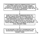
- FIG. 3 is a flow chart depicting functions that can be carried out in accordance with the present method.
- FIG. 4 is another flow chart depicting functions that can be carried out in accordance with the present method.
- FIG. 5 is a simplified block diagram of a representative UE arranged to implement aspects of the present method.
- FIG. 1 is a simplified block diagram of an example communication system 100 in which the present method can be implemented.
- the example system 100 includes a radio access network (RAN) 102 having one or more base stations 104 (e.g., base transceiver stations (BTS), access nodes, node-Bs, eNodeBs (eNB), or the like) that radiate to define a number of coverage areas, where each coverage area is operating on one or more carrier frequencies or blocks of frequencies.
- BTS base transceiver stations
- eNB eNodeBs
- the RAN 102 then includes supporting infrastructure 106 , such as a base station controller, radio network controller, mobility management entity, mobile switching center, and/or gateway, which may function to control aspects of base station operation and/or to provide connectivity with one or more transport networks 108 such as the PSTN and/or the Internet.
- supporting infrastructure 106 such as a base station controller, radio network controller, mobility management entity, mobile switching center, and/or gateway, which may function to control aspects of base station operation and/or to provide connectivity with one or more transport networks 108 such as the PSTN and/or the Internet.
- FIG. 1 further illustrates a representative UE 110 that is located within coverage of the RAN 102 and being served by a given base station of the one or more base stations 104 over an air interface 112 .
- the UE 110 may be any device that is equipped to engage in wireless communication with the RAN 102 and to carry out various UE functions described herein.
- the UE may be a cell phone, or a wirelessly-equipped tablet, computer, tracking device, appliance, embedded wireless module, or other wirelessly-equipped device of a type now known or later developed, whether or not operated by a “user.”
- the UE may seek to engage in communication with a second base station (the same or different base station) on a new carrier frequency.
- the UE may use the same air interface protocol or different air interface protocols for these respective communications on the old and new carrier frequencies.
- the UE may typically engage in the power control process described above in order to establish a suitable initial transmit power for communication with the second base station on the new carrier frequency. The present method can help the UE to reach that suitable initial transmit power more quickly.
- the UE may consider various factors when determining a suitable initial transmit power to use for communication with the second base station on the new carrier frequency. For instance, the UE may determine the initial transmit power based at least in part on a difference between the new carrier frequency and the old carrier frequency on which the UE was served by the first base station. Additionally or alternatively, the UE may determine the initial transmit power based at least in part on a difference in a distance between the UE and the first base station and a distance between the UE and the second base station.
- the UE may first determine a baseline transmit power based on preceding communications (access or bearer) with the first base station that the UE had used to determine a suitable transmit power on the old carrier frequency. Namely, the UE may select the baseline initial transmit power to be the same transmit power that the UE was using for access or bearer transmissions to the first base station on the old carrier frequency or the same transmit power that the first base station used for access or bearer transmissions to the UE. For instance, the UE may determine the baseline transmit power based on an uplink and/or downlink signal strength of these transmissions on the old carrier frequency.
- the UE may then (1) adjust from that baseline transmit power based on one or more of the factors noted above and (2) use the adjusted transmit power for an initial transmission to the second base station on the new carrier frequency for access or bearer communications.
- FIGS. 2A-2C illustrate example scenarios in which the disclosed method may be performed.
- the UE 202 may seek to be served by a second base station on a different carrier frequency (F 2 ) that is the same as the first base station 204 or that is different from, but co-located with the first base station 204 .
- the UE 202 may determine a baseline initial transmit power, as described above. The UE 202 may then adjust that baseline power based on a difference between F 1 and F 2 .
- the UE 202 may increase the baseline transmit power.
- the UE 202 may need a higher transmit power for an initial transmission on F 2 than the transmit power that the UE used for F 1 since higher frequencies like F 2 have a shorter propagation distance and less penetration than lower frequencies like F 1 .
- the UE 202 may increase the baseline transmit power when F 1 is lower than F 2 in order to increase the chance that the second base station 204 successfully receives the initial transmission.
- the UE 202 may then use the increased baseline transmit power as an initial transmit power for the initial transmission to the second base station 204 on F 2 .
- the UE 202 may decrease the baseline transmit power.
- the UE 202 may be able to use a lower transmit power on F 2 than it used on F 1 because lower frequencies like F 2 have a longer propagation distance and greater penetration than higher frequencies like F 1 .
- the UE 202 can decrease the baseline transmit power when F 1 is higher than F 2 , and the second base station 204 may still receive the initial transmission successfully.
- the UE 202 may then use the decreased baseline transmit power as an initial transmit power for the initial transmission to the second base station 204 on F 2 .
- FIG. 2B illustrates a scenario 210 where the first base station 204 and the second base station 206 are different base stations at different locations.
- the UE 202 may switch from being served by the first base station 204 on F 1 to being served by the second base station 206 on F 2 .
- the UE 202 may determine a baseline transmit power and then adjust that baseline transmit power based at least in part on a difference between F 1 and F 2 .
- the UE 202 may further adjust the baseline transmit power based on a difference in the distances between the UE 202 and each respective base station.
- the base stations may broadcast an indication of their geographic locations so that the UE 202 can detect where each base station is, and the UE 202 may also determine its own geographic location. As such, the UE 202 may compare its distance from the first base station 204 to its distance from the second base station 206 , and use that comparison to further adjust the baseline transmit power. In the scenario 200 shown in FIG. 2A , however, where the two base stations are either the same base station or are co-located, such a comparison may result in a difference of zero. Thus, the UE 202 would make little or no distance-based adjustment to the baseline transmit power in that scenario 200 .
- FIG. 2C illustrates a more detailed example 220 of the scenario in FIG. 2B .
- the first base station 204 may be located at a first distance (d 1 ) from the UE 202
- the second base station 206 may be located at a different, second distance (d 2 ) from the UE 202 .
- the UE 202 may adjust the baseline transmit power based on the difference between F 1 and F 2 as described above.
- the UE 202 may then compare d 1 and d 2 , and that comparison may give rise to an additional, distance-based adjustment by the UE 202 to the frequency-based adjusted baseline transmit power.
- the UE 202 may increase the frequency-based adjusted baseline transmit power.
- the initial transmission will have to travel a larger distance to the second base station 206 than the UE's 202 communications had to travel to the first base station 204 .
- the UE 202 increasing the frequency-based adjusted baseline transmit power may further increase the chance that the second base station 206 successfully receives the initial transmission.
- the UE 202 may determine an adjustment to the baseline transmit power based on a comparison of F 1 and F 2 .
- the UE 202 may double the frequency-based adjusted baseline transmit power to compensate for the larger distance, and then use the resulting transmit power as an initial transmit power for the initial transmission to the second base station 206 on F 2 .
- the UE 202 may decrease the frequency-based adjusted baseline transmit power because the initial transmission does not have to travel as far to the second base station 206 as UE's 202 communications had to travel to the first base station 204 .
- the UE 202 can thus use less power for the initial transmission.
- the UE 202 may first determine an adjustment to the baseline transmit power based on a comparison of F 1 and F 2 .
- the UE 202 may divide the frequency-based adjusted baseline transmit power by two, and then use the resulting transmit power as an initial transmit power for the initial transmission to the second base station 206 on F 2 .
- FIG. 3 is a flow chart depicting functions that can be carried out in accordance with the present method.
- the present method will be assumed to be carried out by a UE with respect to the network arrangements and scenarios illustrated in FIGS. 1 and 2 . It should be understood, however, that in other examples, the present method may also be carried out with respect to other arrangements and scenarios.
- the present method may include one or more operations, functions, or actions as illustrated by one or more of blocks 300 - 304 .
- the method involves a UE determining, based on communication by the UE on a first carrier frequency, a baseline initial transmit power for the UE to use for an initial transmission from the UE to a cellular base station.
- the method involves, responsive to the initial transmission being on a second carrier frequency different than the first carrier frequency, the UE adjusting the baseline initial transmit power to establish an adjusted initial transmit power.
- the method then involves the UE engaging in the initial transmission using the adjusted baseline initial transmit power.
- the UE may determine the baseline initial transmit power based on a transmit power that the UE used for a preceding uplink communication on the first carrier frequency or based on a transmit power of a preceding downlink communication that the UE received on the first carrier frequency. After the UE has determined the baseline initial transmit power, the UE may then adjust from that baseline initial transmit power based on a difference between the first and second carrier frequencies. By way of example, if the second carrier frequency is higher than the first carrier frequency, the UE may responsively increase the baseline initial transmit power. Whereas, if the second carrier frequency is lower than the first carrier frequency, the UE may responsively decrease the baseline initial transmit power.
- the UE's communication on the first carrier frequency may have been with a first base station, and that the UE's initial transmission on the second carrier frequency may be an initial transmission to a second base station that is either the same base station as the first base station or a different base station that is co-located with the first base station.
- the first and second base stations may not be the same or co-located. Rather, the first base station may be located at a first geographic location and the second base station may be located at a second geographic location different than the first geographic location. In such a scenario, the UE may determine that the first and second base stations are not co-located and then adjust the baseline initial transmit power responsive to that determination.
- the UE may determine that a first distance between a geographic location of the UE and the first geographic location of the first base station is less than a second distance between the geographic location of the UE and the second geographic location of the second base station, and may adjust the baseline initial transmit power responsive to that determination.
- the UE may determine that the first distance is greater than the second distance, and may adjust the baseline initial transmit power responsive to that determination.
- these distance-based adjustments to the baseline initial transmit power may be made as an additional adjustment to the baseline initial transmit power after the UE has already adjusted the baseline initial transmit power based on the difference between the first and second carrier frequencies. The UE may then engage in the initial transmission using the resulting transmit power.
- FIG. 4 is next another, more specific flow chart depicting functions that can be carried out in accordance with the present method.
- the method involves the UE determining, based on communication by the UE with a first base station on a first carrier frequency, a baseline initial transmit power for the UE to use for an initial transmission from the UE to a second base station.
- the method involves, based on (i) the initial transmission being on a second carrier frequency different than the first carrier frequency and (ii) a comparison of a first geographic location of the first base station with a second geographic location of the second base station, adjusting by the UE the baseline initial transmit power to establish an adjusted initial transmit power.
- the method then involves the UE engaging in the initial transmission to the second base station using the adjusted initial transmit power.
- the UE may determine whether the first carrier frequency is lower (or higher) than the second carrier frequency, and then increase (or decrease) the baseline initial transmit power based on that determination. In turn, the UE may make further adjustments to the frequency-based adjusted baseline initial transmit power based on the comparison of the first geographic location of the first base station with the second geographic location of the second base station. In particular, the UE may compare the geographic locations of the first and second base stations with the UE's own geographic location. For instance, the UE's geographic location may be at a first distance from the first geographic location of the first base station and at a second distance from the second geographic location of the second base station.
- the UE may responsively increase the baseline initial transmit power in order to determine the adjusted baseline initial transmit power. Whereas, if the comparison indicates that the first distance is greater than the second distance, the UE may responsively decrease the baseline initial transmit power in order to determine the adjusted baseline initial transmit power. In either scenario, the UE may increase or decrease the baseline initial transmit power by multiplying the baseline initial transmit power by a ratio of the second distance to the first distance.
- FIG. 5 is next a simplified block diagram of a UE 500 arranged to implement the present method.
- the UE includes a wireless communication interface 502 and a control unit 504 , both of which may be communicatively linked together by a system bus network, or other connection mechanism 506 .
- the wireless communication interface 502 may include an antenna structure and associated components (e.g., a mobile station modem chipset) for engaging in wireless communication with a RAN that radiates to define a plurality of wireless coverage areas each operating on one or more carrier frequencies.
- the wireless communication interface 502 may support communication on various carrier frequencies and may comprise an integrated circuit that is arranged with logic compliant with an applicable air interface protocol such as one of those noted above for instance.
- the UE 500 may also include a multi-mode radio arranged to support service according to various air interface protocols. Accordingly, the UE's communication on the first carrier frequency and the UE's communication on the second carrier frequency may use the same air interface protocol or different air interface protocols, as noted above.
- the control unit 504 may then be configured to carry out various functions described herein, such as to determine, based on communication by the UE on a first carrier frequency and based on a second carrier frequency being different than the first carrier frequency, an initial transmit power for the UE to use for an initial transmission from the UE to a cellular base station on the second carrier frequency.
- the wireless communication interface 500 may be configured to provide the initial transmission to the cellular base station, under direction of the control unit for instance.
- control unit 504 may be integrated with the wireless communication interface 502 .
- program logic on a wireless communication interface chipset may be arranged to carry out the functions of the control unit.
- control unit may comprise a processing unit programmed with instructions to carry out the monitoring and the defining.
- control unit may comprise one or more general-purpose processors (e.g., microprocessors) and/or one or more special-purpose processors (e.g., application specific integrated circuits), non-transitory data storage, and program instructions stored in or encoded on the data storage and executable by the processor(s) to carry out various described functions.
Landscapes
- Engineering & Computer Science (AREA)
- Computer Networks & Wireless Communication (AREA)
- Signal Processing (AREA)
- Mobile Radio Communication Systems (AREA)
Abstract
Description
Claims (16)
Priority Applications (1)
| Application Number | Priority Date | Filing Date | Title |
|---|---|---|---|
| US14/209,591 US9319988B1 (en) | 2014-04-11 | 2014-04-11 | Method and system for determining initial transmission power |
Applications Claiming Priority (1)
| Application Number | Priority Date | Filing Date | Title |
|---|---|---|---|
| US14/209,591 US9319988B1 (en) | 2014-04-11 | 2014-04-11 | Method and system for determining initial transmission power |
Publications (1)
| Publication Number | Publication Date |
|---|---|
| US9319988B1 true US9319988B1 (en) | 2016-04-19 |
Family
ID=55700187
Family Applications (1)
| Application Number | Title | Priority Date | Filing Date |
|---|---|---|---|
| US14/209,591 Active 2034-04-26 US9319988B1 (en) | 2014-04-11 | 2014-04-11 | Method and system for determining initial transmission power |
Country Status (1)
| Country | Link |
|---|---|
| US (1) | US9319988B1 (en) |
Cited By (2)
| Publication number | Priority date | Publication date | Assignee | Title |
|---|---|---|---|---|
| US20230083325A1 (en) * | 2018-01-10 | 2023-03-16 | Comcast Cable Communications, Llc | Power Control for Channel State Information |
| EP4478794A1 (en) * | 2023-06-13 | 2024-12-18 | Sharp Kabushiki Kaisha | Access point apparatus, station apparatus, and communication method |
Citations (15)
| Publication number | Priority date | Publication date | Assignee | Title |
|---|---|---|---|---|
| US20080002646A1 (en) * | 2006-06-30 | 2008-01-03 | Telefonaktiebolaget Lm Ericsson (Publ) | Enhancing coverage for high speed downlink packet access (hsdpa) channel |
| US20080254820A1 (en) * | 2005-09-18 | 2008-10-16 | Yaron Alpert | Power Control in Wireless Communications Networks During Hand-Over |
| US20090088083A1 (en) * | 2007-09-28 | 2009-04-02 | Ntt Docomo, Inc. | Base station, receiving device, mobile terminal, and frequency sharing method |
| US20100062813A1 (en) * | 2008-09-10 | 2010-03-11 | Skyworks Solutions, Inc. | Power amplifier load line switch for a portable transceiver |
| US20100167660A1 (en) * | 2008-12-25 | 2010-07-01 | Kabushiki Kaisha Toshiba | Wireless communication apparatus and wireless communication method |
| US20120115535A1 (en) * | 2010-11-09 | 2012-05-10 | Samsung Electronics Co. Ltd. | Method and apparatus for uplink power control using ranging signal in wireless communication system |
| US20120135777A1 (en) * | 2010-11-30 | 2012-05-31 | Motorola, Inc. | Methods for using effective radiated transmit power of a base station at a wireless communication device to determine uplink transmission range and/or to adjust transmit power |
| US20120252453A1 (en) * | 2010-09-24 | 2012-10-04 | Qualcomm Incorporated | Power control for a network of access points |
| US20120329503A1 (en) * | 2011-06-21 | 2012-12-27 | Telefonaktiebolaget L M Ericsson (Publ) | Systems and Methods For Controlling The Power at Which a Communication Device Transmits an Uplink Signal |
| US8391859B1 (en) | 2009-08-12 | 2013-03-05 | Sprint Spectrum L.P. | Redirection of a roaming wireless communication device and nearby home base station to achieve home carrier service |
| US20130077502A1 (en) * | 2011-09-23 | 2013-03-28 | Qualcomm Incorporated | Adjusting repeater gains based upon received downlink power level |
| US20130142113A1 (en) * | 2011-11-04 | 2013-06-06 | Mo-Han Fong | Path-loss estimation for uplink power control in a carrier agregation environment |
| US20130157651A1 (en) * | 2011-06-20 | 2013-06-20 | Qualcomm Incorporated | Methods and apparatus for deployment and control of base stations |
| US8526990B1 (en) * | 2010-03-17 | 2013-09-03 | Sprint Spectrum L.P. | Determination of initial transmit power based on shared transmit-power information |
| US20130343288A1 (en) * | 2012-06-21 | 2013-12-26 | Nokia Corporation | Power Control For LTE Deployment In Unlicensed Band |
-
2014
- 2014-04-11 US US14/209,591 patent/US9319988B1/en active Active
Patent Citations (15)
| Publication number | Priority date | Publication date | Assignee | Title |
|---|---|---|---|---|
| US20080254820A1 (en) * | 2005-09-18 | 2008-10-16 | Yaron Alpert | Power Control in Wireless Communications Networks During Hand-Over |
| US20080002646A1 (en) * | 2006-06-30 | 2008-01-03 | Telefonaktiebolaget Lm Ericsson (Publ) | Enhancing coverage for high speed downlink packet access (hsdpa) channel |
| US20090088083A1 (en) * | 2007-09-28 | 2009-04-02 | Ntt Docomo, Inc. | Base station, receiving device, mobile terminal, and frequency sharing method |
| US20100062813A1 (en) * | 2008-09-10 | 2010-03-11 | Skyworks Solutions, Inc. | Power amplifier load line switch for a portable transceiver |
| US20100167660A1 (en) * | 2008-12-25 | 2010-07-01 | Kabushiki Kaisha Toshiba | Wireless communication apparatus and wireless communication method |
| US8391859B1 (en) | 2009-08-12 | 2013-03-05 | Sprint Spectrum L.P. | Redirection of a roaming wireless communication device and nearby home base station to achieve home carrier service |
| US8526990B1 (en) * | 2010-03-17 | 2013-09-03 | Sprint Spectrum L.P. | Determination of initial transmit power based on shared transmit-power information |
| US20120252453A1 (en) * | 2010-09-24 | 2012-10-04 | Qualcomm Incorporated | Power control for a network of access points |
| US20120115535A1 (en) * | 2010-11-09 | 2012-05-10 | Samsung Electronics Co. Ltd. | Method and apparatus for uplink power control using ranging signal in wireless communication system |
| US20120135777A1 (en) * | 2010-11-30 | 2012-05-31 | Motorola, Inc. | Methods for using effective radiated transmit power of a base station at a wireless communication device to determine uplink transmission range and/or to adjust transmit power |
| US20130157651A1 (en) * | 2011-06-20 | 2013-06-20 | Qualcomm Incorporated | Methods and apparatus for deployment and control of base stations |
| US20120329503A1 (en) * | 2011-06-21 | 2012-12-27 | Telefonaktiebolaget L M Ericsson (Publ) | Systems and Methods For Controlling The Power at Which a Communication Device Transmits an Uplink Signal |
| US20130077502A1 (en) * | 2011-09-23 | 2013-03-28 | Qualcomm Incorporated | Adjusting repeater gains based upon received downlink power level |
| US20130142113A1 (en) * | 2011-11-04 | 2013-06-06 | Mo-Han Fong | Path-loss estimation for uplink power control in a carrier agregation environment |
| US20130343288A1 (en) * | 2012-06-21 | 2013-12-26 | Nokia Corporation | Power Control For LTE Deployment In Unlicensed Band |
Cited By (2)
| Publication number | Priority date | Publication date | Assignee | Title |
|---|---|---|---|---|
| US20230083325A1 (en) * | 2018-01-10 | 2023-03-16 | Comcast Cable Communications, Llc | Power Control for Channel State Information |
| EP4478794A1 (en) * | 2023-06-13 | 2024-12-18 | Sharp Kabushiki Kaisha | Access point apparatus, station apparatus, and communication method |
Similar Documents
| Publication | Publication Date | Title |
|---|---|---|
| US10849104B2 (en) | Methods and devices for broadcasting system information on demand | |
| US12342274B2 (en) | Cell selection based on user capability | |
| US20190007844A1 (en) | Method and apparatus for controlling beam transmission to grouped user equipment (ues) | |
| US10904771B1 (en) | Method and apparatus for invoking beamforming responsive to carrier transition | |
| US10420103B2 (en) | Uplink inter-site carrier aggregation based on UE transmission power and secondary cell load | |
| US10440635B2 (en) | Network device and user device and methods thereof | |
| JP6190960B2 (en) | Communication system radio coverage reconstruction based on available capacity of compensation cell | |
| CN103179681A (en) | Decoupled downlink and uplink | |
| US11051186B1 (en) | Dynamic control of single-RAT service based on threshold presence of dual-RAT-capable devices | |
| US9253662B1 (en) | Method and system for dynamically activating a relay | |
| US20240389063A1 (en) | Wireless communication with resource configuration for positioning | |
| US20170064652A1 (en) | User device, access node device, central network controller and corresponding methods | |
| US9843972B2 (en) | Incremental compensation cell expansion during communications system radio coverage reconfiguration | |
| US9226210B1 (en) | Use of fallback carrier load to manage fallback communication setup latency | |
| EP2589233B1 (en) | Method and apparatus for establishing and maintaining a spectrally efficient multicast group call | |
| JP2018510563A (en) | Frequency band sharing method, apparatus and system | |
| US10123339B1 (en) | Transitioning a UE to a new PCell without handover processing | |
| US9370004B2 (en) | Traffic management for user equipment devices | |
| US9319988B1 (en) | Method and system for determining initial transmission power | |
| US10433222B1 (en) | Use of uplink transmission power from distant devices as basis to control service | |
| CN108024311A (en) | Method and device for updating system information | |
| CN107113692B (en) | Communication method and apparatus | |
| US9357448B1 (en) | Method and system for dynamically updating a handover-scan-list maintained by a base station | |
| US9629136B1 (en) | Method and system for reducing PRACH interference | |
| WO2017091988A1 (en) | Information transmission method, base station and communication system |
Legal Events
| Date | Code | Title | Description |
|---|---|---|---|
| AS | Assignment |
Owner name: SPRINT SPECTRUM L.P., KANSAS Free format text: ASSIGNMENT OF ASSIGNORS INTEREST;ASSIGNORS:RAI, DEVESHKUMAR N.;VELUSAMY, SARAVANA;MALHOTRA, RAJIL;AND OTHERS;REEL/FRAME:032433/0884 Effective date: 20140311 |
|
| STCF | Information on status: patent grant |
Free format text: PATENTED CASE |
|
| AS | Assignment |
Owner name: DEUTSCHE BANK TRUST COMPANY AMERICAS, NEW YORK Free format text: GRANT OF FIRST PRIORITY AND JUNIOR PRIORITY SECURITY INTEREST IN PATENT RIGHTS;ASSIGNOR:SPRINT SPECTRUM L.P.;REEL/FRAME:041937/0632 Effective date: 20170203 |
|
| MAFP | Maintenance fee payment |
Free format text: PAYMENT OF MAINTENANCE FEE, 4TH YEAR, LARGE ENTITY (ORIGINAL EVENT CODE: M1551); ENTITY STATUS OF PATENT OWNER: LARGE ENTITY Year of fee payment: 4 |
|
| AS | Assignment |
Owner name: DEUTSCHE BANK TRUST COMPANY AMERICAS, NEW YORK Free format text: SECURITY AGREEMENT;ASSIGNORS:T-MOBILE USA, INC.;ISBV LLC;T-MOBILE CENTRAL LLC;AND OTHERS;REEL/FRAME:053182/0001 Effective date: 20200401 |
|
| AS | Assignment |
Owner name: SPRINT SPECTRUM L.P., KANSAS Free format text: TERMINATION AND RELEASE OF FIRST PRIORITY AND JUNIOR PRIORITY SECURITY INTEREST IN PATENT RIGHTS;ASSIGNOR:DEUTSCHE BANK TRUST COMPANY AMERICAS;REEL/FRAME:052313/0299 Effective date: 20200401 |
|
| AS | Assignment |
Owner name: SPRINT SPECTRUM LLC, WASHINGTON Free format text: CHANGE OF NAME;ASSIGNOR:SPRINT SPECTRUM L.P.;REEL/FRAME:059044/0022 Effective date: 20210325 |
|
| AS | Assignment |
Owner name: SPRINT SPECTRUM LLC, KANSAS Free format text: RELEASE BY SECURED PARTY;ASSIGNOR:DEUTSCHE BANK TRUST COMPANY AMERICAS;REEL/FRAME:062595/0001 Effective date: 20220822 Owner name: SPRINT INTERNATIONAL INCORPORATED, KANSAS Free format text: RELEASE BY SECURED PARTY;ASSIGNOR:DEUTSCHE BANK TRUST COMPANY AMERICAS;REEL/FRAME:062595/0001 Effective date: 20220822 Owner name: SPRINT COMMUNICATIONS COMPANY L.P., KANSAS Free format text: RELEASE BY SECURED PARTY;ASSIGNOR:DEUTSCHE BANK TRUST COMPANY AMERICAS;REEL/FRAME:062595/0001 Effective date: 20220822 Owner name: SPRINTCOM LLC, KANSAS Free format text: RELEASE BY SECURED PARTY;ASSIGNOR:DEUTSCHE BANK TRUST COMPANY AMERICAS;REEL/FRAME:062595/0001 Effective date: 20220822 Owner name: CLEARWIRE IP HOLDINGS LLC, KANSAS Free format text: RELEASE BY SECURED PARTY;ASSIGNOR:DEUTSCHE BANK TRUST COMPANY AMERICAS;REEL/FRAME:062595/0001 Effective date: 20220822 Owner name: CLEARWIRE COMMUNICATIONS LLC, KANSAS Free format text: RELEASE BY SECURED PARTY;ASSIGNOR:DEUTSCHE BANK TRUST COMPANY AMERICAS;REEL/FRAME:062595/0001 Effective date: 20220822 Owner name: BOOST WORLDWIDE, LLC, KANSAS Free format text: RELEASE BY SECURED PARTY;ASSIGNOR:DEUTSCHE BANK TRUST COMPANY AMERICAS;REEL/FRAME:062595/0001 Effective date: 20220822 Owner name: ASSURANCE WIRELESS USA, L.P., KANSAS Free format text: RELEASE BY SECURED PARTY;ASSIGNOR:DEUTSCHE BANK TRUST COMPANY AMERICAS;REEL/FRAME:062595/0001 Effective date: 20220822 Owner name: T-MOBILE USA, INC., WASHINGTON Free format text: RELEASE BY SECURED PARTY;ASSIGNOR:DEUTSCHE BANK TRUST COMPANY AMERICAS;REEL/FRAME:062595/0001 Effective date: 20220822 Owner name: T-MOBILE CENTRAL LLC, WASHINGTON Free format text: RELEASE BY SECURED PARTY;ASSIGNOR:DEUTSCHE BANK TRUST COMPANY AMERICAS;REEL/FRAME:062595/0001 Effective date: 20220822 Owner name: PUSHSPRING, LLC, WASHINGTON Free format text: RELEASE BY SECURED PARTY;ASSIGNOR:DEUTSCHE BANK TRUST COMPANY AMERICAS;REEL/FRAME:062595/0001 Effective date: 20220822 Owner name: LAYER3 TV, LLC, WASHINGTON Free format text: RELEASE BY SECURED PARTY;ASSIGNOR:DEUTSCHE BANK TRUST COMPANY AMERICAS;REEL/FRAME:062595/0001 Effective date: 20220822 Owner name: IBSV LLC, WASHINGTON Free format text: RELEASE BY SECURED PARTY;ASSIGNOR:DEUTSCHE BANK TRUST COMPANY AMERICAS;REEL/FRAME:062595/0001 Effective date: 20220822 Owner name: IBSV LLC, WASHINGTON Free format text: RELEASE OF SECURITY INTEREST;ASSIGNOR:DEUTSCHE BANK TRUST COMPANY AMERICAS;REEL/FRAME:062595/0001 Effective date: 20220822 Owner name: LAYER3 TV, LLC, WASHINGTON Free format text: RELEASE OF SECURITY INTEREST;ASSIGNOR:DEUTSCHE BANK TRUST COMPANY AMERICAS;REEL/FRAME:062595/0001 Effective date: 20220822 Owner name: PUSHSPRING, LLC, WASHINGTON Free format text: RELEASE OF SECURITY INTEREST;ASSIGNOR:DEUTSCHE BANK TRUST COMPANY AMERICAS;REEL/FRAME:062595/0001 Effective date: 20220822 Owner name: T-MOBILE CENTRAL LLC, WASHINGTON Free format text: RELEASE OF SECURITY INTEREST;ASSIGNOR:DEUTSCHE BANK TRUST COMPANY AMERICAS;REEL/FRAME:062595/0001 Effective date: 20220822 Owner name: T-MOBILE USA, INC., WASHINGTON Free format text: RELEASE OF SECURITY INTEREST;ASSIGNOR:DEUTSCHE BANK TRUST COMPANY AMERICAS;REEL/FRAME:062595/0001 Effective date: 20220822 Owner name: ASSURANCE WIRELESS USA, L.P., KANSAS Free format text: RELEASE OF SECURITY INTEREST;ASSIGNOR:DEUTSCHE BANK TRUST COMPANY AMERICAS;REEL/FRAME:062595/0001 Effective date: 20220822 Owner name: BOOST WORLDWIDE, LLC, KANSAS Free format text: RELEASE OF SECURITY INTEREST;ASSIGNOR:DEUTSCHE BANK TRUST COMPANY AMERICAS;REEL/FRAME:062595/0001 Effective date: 20220822 Owner name: CLEARWIRE COMMUNICATIONS LLC, KANSAS Free format text: RELEASE OF SECURITY INTEREST;ASSIGNOR:DEUTSCHE BANK TRUST COMPANY AMERICAS;REEL/FRAME:062595/0001 Effective date: 20220822 Owner name: CLEARWIRE IP HOLDINGS LLC, KANSAS Free format text: RELEASE OF SECURITY INTEREST;ASSIGNOR:DEUTSCHE BANK TRUST COMPANY AMERICAS;REEL/FRAME:062595/0001 Effective date: 20220822 Owner name: SPRINTCOM LLC, KANSAS Free format text: RELEASE OF SECURITY INTEREST;ASSIGNOR:DEUTSCHE BANK TRUST COMPANY AMERICAS;REEL/FRAME:062595/0001 Effective date: 20220822 Owner name: SPRINT COMMUNICATIONS COMPANY L.P., KANSAS Free format text: RELEASE OF SECURITY INTEREST;ASSIGNOR:DEUTSCHE BANK TRUST COMPANY AMERICAS;REEL/FRAME:062595/0001 Effective date: 20220822 Owner name: SPRINT INTERNATIONAL INCORPORATED, KANSAS Free format text: RELEASE OF SECURITY INTEREST;ASSIGNOR:DEUTSCHE BANK TRUST COMPANY AMERICAS;REEL/FRAME:062595/0001 Effective date: 20220822 Owner name: SPRINT SPECTRUM LLC, KANSAS Free format text: RELEASE OF SECURITY INTEREST;ASSIGNOR:DEUTSCHE BANK TRUST COMPANY AMERICAS;REEL/FRAME:062595/0001 Effective date: 20220822 |
|
| MAFP | Maintenance fee payment |
Free format text: PAYMENT OF MAINTENANCE FEE, 8TH YEAR, LARGE ENTITY (ORIGINAL EVENT CODE: M1552); ENTITY STATUS OF PATENT OWNER: LARGE ENTITY Year of fee payment: 8 |