US9319669B2 - Image processing device and image processing method - Google Patents
Image processing device and image processing method Download PDFInfo
- Publication number
- US9319669B2 US9319669B2 US14/167,620 US201414167620A US9319669B2 US 9319669 B2 US9319669 B2 US 9319669B2 US 201414167620 A US201414167620 A US 201414167620A US 9319669 B2 US9319669 B2 US 9319669B2
- Authority
- US
- United States
- Prior art keywords
- color regions
- color
- regions
- threshold value
- marker
- Prior art date
- Legal status (The legal status is an assumption and is not a legal conclusion. Google has not performed a legal analysis and makes no representation as to the accuracy of the status listed.)
- Expired - Fee Related
Links
Images


Classifications
-
- H—ELECTRICITY
- H04—ELECTRIC COMMUNICATION TECHNIQUE
- H04N—PICTORIAL COMMUNICATION, e.g. TELEVISION
- H04N17/00—Diagnosis, testing or measuring for television systems or their details
- H04N17/002—Diagnosis, testing or measuring for television systems or their details for television cameras
-
- G—PHYSICS
- G06—COMPUTING OR CALCULATING; COUNTING
- G06T—IMAGE DATA PROCESSING OR GENERATION, IN GENERAL
- G06T7/00—Image analysis
- G06T7/70—Determining position or orientation of objects or cameras
- G06T7/73—Determining position or orientation of objects or cameras using feature-based methods
- G06T7/74—Determining position or orientation of objects or cameras using feature-based methods involving reference images or patches
-
- G06K9/4652—
-
- G06T11/001—
-
- G—PHYSICS
- G06—COMPUTING OR CALCULATING; COUNTING
- G06T—IMAGE DATA PROCESSING OR GENERATION, IN GENERAL
- G06T11/00—Two-dimensional [2D] image generation
- G06T11/10—Texturing; Colouring; Generation of textures or colours
-
- G—PHYSICS
- G06—COMPUTING OR CALCULATING; COUNTING
- G06T—IMAGE DATA PROCESSING OR GENERATION, IN GENERAL
- G06T2207/00—Indexing scheme for image analysis or image enhancement
- G06T2207/10—Image acquisition modality
- G06T2207/10024—Color image
-
- G—PHYSICS
- G06—COMPUTING OR CALCULATING; COUNTING
- G06T—IMAGE DATA PROCESSING OR GENERATION, IN GENERAL
- G06T2207/00—Indexing scheme for image analysis or image enhancement
- G06T2207/30—Subject of image; Context of image processing
- G06T2207/30204—Marker
- G06T2207/30208—Marker matrix
-
- G—PHYSICS
- G06—COMPUTING OR CALCULATING; COUNTING
- G06T—IMAGE DATA PROCESSING OR GENERATION, IN GENERAL
- G06T2207/00—Indexing scheme for image analysis or image enhancement
- G06T2207/30—Subject of image; Context of image processing
- G06T2207/30248—Vehicle exterior or interior
- G06T2207/30252—Vehicle exterior; Vicinity of vehicle
-
- G06T7/0081—
-
- G—PHYSICS
- G06—COMPUTING OR CALCULATING; COUNTING
- G06T—IMAGE DATA PROCESSING OR GENERATION, IN GENERAL
- G06T7/00—Image analysis
- G06T7/10—Segmentation; Edge detection
- G06T7/11—Region-based segmentation
-
- G06T7/408—
-
- G—PHYSICS
- G06—COMPUTING OR CALCULATING; COUNTING
- G06T—IMAGE DATA PROCESSING OR GENERATION, IN GENERAL
- G06T7/00—Image analysis
- G06T7/90—Determination of colour characteristics
-
- G—PHYSICS
- G06—COMPUTING OR CALCULATING; COUNTING
- G06T—IMAGE DATA PROCESSING OR GENERATION, IN GENERAL
- G06T9/00—Image coding
- G06T9/005—Statistical coding, e.g. Huffman, run length coding
-
- G—PHYSICS
- G06—COMPUTING OR CALCULATING; COUNTING
- G06V—IMAGE OR VIDEO RECOGNITION OR UNDERSTANDING
- G06V10/00—Arrangements for image or video recognition or understanding
- G06V10/40—Extraction of image or video features
- G06V10/56—Extraction of image or video features relating to colour
-
- G—PHYSICS
- G06—COMPUTING OR CALCULATING; COUNTING
- G06V—IMAGE OR VIDEO RECOGNITION OR UNDERSTANDING
- G06V2201/00—Indexing scheme relating to image or video recognition or understanding
- G06V2201/09—Recognition of logos
Definitions
- the embodiments discussed herein are related to an image processing device, an image processing method, and an image processing program which are utilized for camera calibration processing for calculation of a position and a posture of a camera and is used for extraction of a coordinate of a marker on a picked-up image, for example.
- a surrounding image of driver's own vehicle is acquired by a camera and the acquired image is presented to the driver so as to assist the driver in checking a surrounding situation of the driver's own vehicle and thus contribute to the driver's safe driving.
- a plurality of cameras are provided around a driver's own vehicle and images which are picked up by respective cameras are synthesized, enabling the driver to visually recognize a wide-ranging image of the surroundings of the driver's own vehicle.
- a plurality of cameras have to be installed on predetermined positions and in predetermined camera-directions so as to obtain an image which provides no feeling of strangeness to a driver, that is, a synthesis image in which no seams of images are out of alignment or images are not inclined, as a result of synchronization of a plurality of picked-up images.
- cameras are attached on a vehicle, so that installation positions and angles of the cameras may change due to vibration caused by moving of the vehicle and the like. Therefore, whether or not a gap is generated on installation positions and angles of the cameras has to be confirmed at arbitrary timing after start of use such as shipping and vehicle inspection, and thus calibration processing of the installation positions and angles of the cameras has to be performed.
- a marker (jig) which is installed on a prescribed position in a camera shooting range is shot and a marker position on the shot image, in other words, a coordinate of a feature point of the marker on a picked-up image is associated with a prescribed position.
- a marker used for the calibration processing a marker which has a pattern of which a feature point is easily extracted on a picked-up image is preferably used.
- a checkered marker is generally used.
- a central point of an intersection of a checkered pattern is extracted as a feature point, for example.
- an image processing device includes a processor; and a memory which stores a plurality of instructions, which when executed by the processor, cause the processor to execute, acquiring an image that includes a marker that includes a plurality of first color regions and a plurality of second color regions, of which a color is different from a color of the first color regions, the plurality of first color regions being opposed to each other and the plurality of second color regions being opposed to each other; extracting the first color regions or the second color regions from the image; reducing the first color regions or the second color regions until a first degree of similarity between a shape of the first color regions or the second color regions, the first color regions or the second color regions being extracted, and a predetermined elliptical shape satisfies a predetermined first threshold value; and calculating a second degree of similarity between the first color regions or the second color regions, the first color regions or the second color regions satisfying the first threshold value, and a predetermined butterfly shape.
- FIG. 1A illustrates a first example of a marker
- FIG. 1B illustrates a second example of a marker
- FIG. 1C illustrates a third example of a marker
- FIG. 2A is a conceptual diagram illustrating a case in which color regions which constitute a marker are correctly recognized
- FIG. 2B is a conceptual diagram illustrating a case in which color regions which constitute a marker are erroneously recognized
- FIG. 3 is a functional block diagram illustrating an image processing device according to one embodiment
- FIG. 4 illustrates an example of an arrangement state of markers
- FIG. 5 is a flowchart for determining a butterfly shape by a calculation unit
- FIG. 6A illustrates an image before rotation which includes first color regions which do not form a butterfly shape
- FIG. 6B illustrates an image after rotation which includes first color regions which do not form a butterfly shape
- FIG. 6C is a projection histogram of first color regions which do not form a butterfly shape
- FIG. 7A illustrates an image before rotation which includes first color regions which form a butterfly shape
- FIG. 7B illustrates an image after rotation which includes first color regions which form a butterfly shape
- FIG. 7C is a projection histogram of first color regions which form a butterfly shape
- FIG. 8 is a conceptual diagram illustrating a region pair of first color regions and a region pair of second color regions which constitute a marker
- FIG. 9 is a flowchart illustrating image processing performed by the image processing device.
- FIG. 10 is a hardware configuration diagram of an image processing device according to another embodiment.
- FIG. 1A illustrates a first example of a marker.
- FIG. 1B illustrates a second example of a marker.
- FIG. 1C illustrates a third example of a marker.
- Markers in FIGS. 1A to 1C have a checkered pattern.
- the marker has a circular region on a central portion of a square region of approximately 40 centimeters, for example.
- the markers further have a square region on a central portion of the square region of approximately 40 centimeters, for example.
- the marker includes a plurality of first color regions and a plurality of second color regions of which a color is different from that of the first color regions and the first color regions and the second color regions are respectively opposed to each other.
- the marker has a checkered pattern in which white regions and black regions are alternately arranged, for example.
- the circular region or the square region which is positioned on a central portion of the marker has a pair of white regions which are opposed to each other and a pair of black regions which are opposed to each other across the central portion of the marker.
- the marker is set to have a black-and-white checkered pattern, for example, so as to extract a center of the circular region or the square region of the marker as a feature point, for example.
- Description is provided by taking the marker illustrated in FIG. 1A as an example in this embodiment, but the marker illustrated in FIG. 1B or FIG. 1C is also applicable.
- the first color regions correspond to white regions and the second color regions correspond to black regions for the sake of convenience of the description, but associating relation may be prescribed in an opposite manner.
- an image processing device which extracts a feature point of a marker from a blurred image.
- an image processing device which extracts a feature point of a marker even in a blurred image has been disclosed in International Publication Pamphlet No. WO 2012/061205.
- a feature point of a marker is an intersecting point between a pair of white regions and a pair of black regions of a marker having a checkered pattern.
- a method in which color regions of a marker are extracted so as to extract a feature point of the marker on the basis of positional relation of the extracted color regions has been disclosed.
- an influence of a lighting environment in execution of calibration processing causes such shooting that one color regions of a marker are expanded and the other color regions are degenerated. Accordingly, a marker of a picked-up image may appear on the picked-up image in a state that one color regions are eroded (may be referred to as a linked state).
- a predetermined convex shape elliptical shape
- this image processing device calculates a pseudo elliptical shape from candidate regions of color regions which constitute a marker, for example.
- the image processing device compares the elliptical area with areas of the candidate regions and determines as a convex shape (elliptical shape) in a case of a high degree of similarity of areas, so as to specify color regions (a pair of white regions and a pair of black regions) which constitute a marker.
- FIG. 2A is a conceptual diagram of a case in which color regions which constitute a marker are correctly recognized.
- FIG. 2B is conceptual diagram of a case in which color regions which constitute a marker are erroneously recognized.
- color regions for example, white regions
- the inventors have examined setting of a determination condition of similarity with respect to a predetermined elliptical shape to a stricter determination condition so as to be able to exclude a butterfly shape.
- robustness is influenced when a determination condition is set to be stricter in a blurred image.
- a threshold value for similarity determination higher.
- a checkered marker itself is picked up in a distorted manner, causing such problem that a threshold value is not satisfied even if color regions which constitute a marker are separated from each other.
- the inventors have also examined similarity determination by preparing a butterfly-shaped template, but it has become clear that it is also difficult to apply a template because a butterfly shape is variously imaged in a blurred image.
- an image processing device which extracts a feature point of a marker with high precision even in a case in which white regions in a pair which constitute a marker are mutually joined to form a butterfly shape in a blurred image as illustrated in FIG. 2B is disclosed in embodiments of the present disclosure.
- FIG. 3 is a functional block diagram of an image processing device 1 according to one embodiment.
- the image processing device 1 includes an acquisition unit 2 , an extraction unit 3 , a reduction unit 4 , a calculation unit 5 , and a recognition unit 6 .
- the image processing device 1 includes a communication unit, which is not illustrated, and is capable of using a network resource by performing bidirectional data transmission/reception with various external devices via a communication line.
- the acquisition unit 2 is a hardware circuit based on a wired logic, for example. Further, the acquisition unit 2 may be a functional module which is realized by a computer program which is executed in the image processing device 1 .
- the acquisition unit 2 receives an image picked up by an external device.
- the external device which picks up an image is an imaging element, for example.
- the imaging element is an imaging device such as a charge coupled device (CCD) and a complementary metal oxide semiconductor (CMOS) camera, for example.
- CMOS complementary metal oxide semiconductor
- the imaging element may be included in the image processing device 1 as appropriate.
- the imaging element images a marker having a checkered pattern, for example.
- the acquisition unit 2 outputs an image including an acquired marker to the extraction unit 3 .
- FIG. 4 illustrates an example of an arrangement state of markers.
- a plurality of imaging elements 8 a to 8 d are installed on positions on which imaging of entire circumference of a vehicle 7 is enabled, for example, with respect to the vehicle 7 .
- 8 A to 8 D illustrated in FIG. 4 correspond to shooting ranges of the imaging elements 8 a to 8 d which are installed on the vehicle 7 .
- a part of the shooting range 8 A of the imaging element 8 a , a part of the shooting range 8 B of the imaging element 8 b , and a part of the shooting range 8 C of the imaging element 8 c are overlapped with each other.
- a part of the shooting range 8 D of the imaging element 8 d , a part of the shooting range 8 B of the imaging element 8 b , and a part of the shooting range 8 C of the imaging element 8 c are overlapped with each other.
- the vehicle 7 stops at a predetermined stopping position.
- respective imaging elements 8 a to 8 d which are installed on the vehicle 7 arrange markers 9 in the periphery of the vehicle 7 so as to enable shooting of at least four markers, for example.
- the markers 9 may be arranged so that two markers 9 which are shot by certain imaging elements among the four markers 9 are shot also by an adjacent imaging element.
- the markers 9 may be arranged so that one marker 9 which is shot by the imaging element 8 a among the four markers 9 is shot by the imaging element 8 b which is adjacent to the imaging element 8 a.
- the markers 9 may be arranged so that one marker 9 which is shot by the imaging element 8 a among the four markers 9 is shot by the imaging element 8 c which is adjacent to the imaging element 8 a . In other words, it is sufficient to arrange the markers 9 on positions on which shooting ranges of a plurality of imaging elements are overlapped with each other. However, it is assumed that physical arrangement positions of the markers 9 with respect to the vehicle 7 , with the inclusion of overlapped positions, are preliminarily measured.
- the numbers of imaging elements and markers 9 may be one, so that description is provided on the assumption that the numbers of imaging elements and markers 9 are one in embodiment 1. In the following description, a reference numeral of the marker 9 is omitted for the sake of convenience of the description.
- the extraction unit 3 of FIG. 3 is a hardware circuit based on the wired logic, for example. Further, the extraction unit 3 may be a functional module which is realized by a computer program which is executed in the image processing device 1 .
- (x, y) denotes a position of the original image (an origin may be on the upper left end of the image, for example).
- R(x, y), G(x, y), and B(x, y) respectively denote an R component value, a G component value, and a B component value on the position (x, y) of the original image.
- the extraction unit 3 generates binary images from the grayscale image respectively.
- the extraction unit 3 compares a pixel value of a grayscale image with a predetermined threshold value, for example, and performs binarization such that a value equal to or larger than the threshold value is set to “1” and a pixel value smaller than the threshold value is set to “0”, so as to generate a binary image from the grayscale image.
- a predetermined threshold value for example, and performs binarization such that a value equal to or larger than the threshold value is set to “1” and a pixel value smaller than the threshold value is set to “0”, so as to generate a binary image from the grayscale image.
- a candidate of a white region in a checkered pattern is set to “1” and a candidate of a black region is set to “0”.
- the above-mentioned predetermined threshold value does not have to be a fixed value but may be locally determined or dynamically determined in a large sense on the basis of an object image.
- the extraction unit 3 performs labeling with respect to the binarized image obtained through the binarization so as to extract first color regions and second color regions (in other words, white regions or black regions).
- the labeling method 4 linkage (4 neighborhood) method or 8 linkage (8 neighborhood) method which is a method of related art may be used, for example.
- the extraction unit 3 may be provided with an image buffer which stores an extraction result and is not illustrated.
- the image buffer is an image having the same size as the above-mentioned binarized image and is initialized by a white color (1) or a black color (0), for example.
- the image buffer may be provided to the reduction unit 4 or the like instead of the extraction unit 3 .
- the extraction unit 3 outputs the extracted first color regions and second color regions to the reduction unit 4 .
- the reduction unit 4 receives the first color regions and the second color regions which are extracted by the extraction unit 3 from the extraction unit 3 .
- the reduction unit 4 calculates a first degree of similarity between shapes of the first color regions and the second color regions and a predetermined elliptical shape.
- a method for processing the first color regions is described as the following processing. It is possible to process the second color regions (black regions) as well in a similar manner to the first color regions by performing black-white inverting processing, for example, so that detailed description is omitted.
- the reduction unit 4 determines whether or not each of a plurality of first color regions which are included in the binarized image has an elliptical shape. Specifically, the reduction unit 4 first calculates a long axis and a short axis of a pseudo ellipse which corresponds to the first color regions which are extracted by the labeling, through the following procedure.
- the moment M ij is referred also to as (i+j)-order moment.
- a 0-order moment expressed by the following formula is an area of the first color region.
- MG ij ⁇ x,y ( x ⁇ x G ) i ( y ⁇ y G ) j BW ( x,y ) (5)
- second moments around the gravity center (three moments which are MG 20 , MG 02 , and MG 11 ) are referred to as moments of inertia.
- a normalized moment of inertia ⁇ ij which is normalized by the 0-order moment (area of the first color region) is expressed by the following formula.
- a length a of a long axis and a length b of a short axis of an approximate pseudo elliptical shape are calculated as the following formula by using above-mentioned formula 7 so as to execute approximation to an elliptical shape of the first color region (an area is M 00 ).
- the reduction unit 4 determines whether or not the first color region which is a processing object has an elliptical shape on the basis of whether or not a ratio (may be referred to as a first degree of similarity) between the area of the first color region which is the processing object and the area of the pseudo elliptical shape which corresponds to the region satisfies a predetermined threshold value (may be referred to as a first threshold value).
- the reduction unit 4 calculates an evaluation value E by using the following formula for evaluating the ratio (first degree of similarity) of areas and sets the first threshold value to 0.3, for example. In a case of E ⁇ 0.3, the reduction unit 4 determines that the first color region has the elliptical shape, and in a case of E ⁇ 0.3, the reduction unit 4 determines that the first color region does not have the elliptical shape.
- the reduction unit 4 may arbitrarily apply a reduction method and an evaluation method which are disclosed in International Publication Pamphlet No. WO 2012/061205, for example.
- the calculation unit 5 of FIG. 3 is a hardware circuit based on the wired logic, for example. Further, the calculation unit 5 may be a functional module which is realized by a computer program which is executed in the image processing device 1 .
- the calculation unit 5 accesses the reduction unit 4 so as to calculate a second degree of similarity between a first color region which satisfies above-mentioned condition of formula 10 to be determined to have an elliptical shape, in a plurality of first color regions which are included in the binarized image, and a predetermined butterfly shape.
- a technical purpose for calculation, which is performed by the calculation unit 5 of the second degree of similarity between a first color region which is determined to have an elliptical shape and a predetermined butterfly shape is now described.
- first color regions in a pair which constitute a marker are joined with each other to form a butterfly shape when erosion occurs in color regions (for example, when lighting is strong and bright), as illustrated in FIG. 2B .
- Such butterfly shape may satisfy the above-mentioned condition of formula 10 and therefore, degeneration processing is not executed, causing a problem of erroneous detection in which it is difficult to specify a pair of white regions which constitute a marker.
- determination of whether or not to be a butterfly shape is enabled in a case in which the above-mentioned condition of formula 10 is satisfied, it is possible to avoid erroneous detection and enhance robustness.
- a method for calculation, which is performed by the calculation unit 5 of a second degree of similarity to a predetermined butterfly shape will be described later.
- the calculation unit 5 determines that first color regions which are processing objects do not form a butterfly shape, the calculation unit 5 sets the first color regions as candidates of first color regions which constitute a marker.
- the calculation unit 5 may access the image buffer which is included in the extraction unit 3 and copy the first color regions to the image butter so as to delete (black out) a range of first color regions of an original image. Further, when the calculation unit 5 determines that first color regions which are processing objects form a butterfly shape, the calculation unit 5 does not set the first color regions as candidates of first color regions which constitute a marker even if the first color regions have an elliptical shape.
- the calculation unit 5 calculates the second degree of similarity and performs determination processing of whether or not to be a butterfly shape with respect to a plurality of first color regions, candidates of first color regions which constitute a marker are extracted in the image buffer and first color regions which are not candidates remain in an original binarized image.
- the reduction unit 4 performs degeneration processing of the original binarized image.
- the reduction unit 4 executes reduction processing with respect to first color regions which are determined to have no elliptical shape and first color regions which are determined to have an elliptical shape but form a butterfly shape.
- the degeneration processing various techniques of related art such as a method in which pixels of outer circumference of the first color region (white region) are cut (deleted) one by one and a method in which pixels on an edge portion of the first color region are cut by predetermined filtering processing may be used.
- the extraction unit 3 executes labeling again with respect to a binarized image which has been subjected to the degeneration so as to extract first color regions and second color regions (in other words, white regions or black regions) again.
- the reduction unit 4 and the calculation unit 5 repeat the above-described series of processing until first color regions disappear.
- candidates of first color regions which constitute a marker are extracted in the image buffer.
- FIG. 5 is a flowchart of determination of a butterfly shape performed by the calculation unit 5 .
- the calculation unit 5 calculates a gravity center position of first color regions by using the first color regions which is determined to have an elliptical shape, as input data (step S 501 ).
- the calculation unit 5 is capable of calculating a gravity center position of the first color regions on the basis of above-mentioned formula 4.
- the calculation unit 5 calculates a principal axis of inertia of the first color regions which are processing objects (step S 502 ).
- the calculation unit 5 is capable of calculating the principal axis of inertia on the basis of the following formula.
- the principal axis of inertia is a straight line which passes through the gravity center position which is calculated in step S 501 and has an inclination of an angle ⁇ which is calculated on the basis of above-mentioned formula 11.
- the calculation unit 5 generates a projection histogram with respect to the calculated principal axis of inertia in the first color regions which are processing objects (step S 503 ).
- the calculation unit 5 is capable of generating a projection histogram by the following procedure, for example, in step S 503 .
- the number of pixels of the first color regions is counted in each column direction of the rotated image (a longitudinal direction, in other words, a y-axis direction).
- a count result of the number of pixels of each column forms a projection histogram.
- FIG. 6A illustrates an image before rotation which includes first color regions which do not form a butterfly shape.
- FIG. 6B illustrates an image after rotation which includes first color regions which do not form a butterfly shape.
- FIG. 7A illustrates an image before rotation which includes first color regions which form a butterfly shape.
- FIG. 7B illustrates an image after rotation which includes first color regions which form a butterfly shape.
- a gravity center coordinate (x G , y G ) and a principal axis of inertia having an inclination ⁇ are specified in the first color regions which are included in an image of which an origin is on the upper-left end.
- the first color regions are rotated so that the direction of the principal axis of inertia is in a direction parallel with the x axis of the image.
- FIG. 6C is a projection histogram of first color regions which do not form a butterfly shape.
- FIG. 7C is a projection histogram of first color regions which form a butterfly shape. It is confirmable that the projection histogram illustrated in FIG. 6C has a unimodal shape and the projection histogram illustrated in FIG. 7C has bimodal-shaped multiple peaks. Accordingly, when a degree of similarity of a projection histogram with respect to a predetermined bimodal shape (may be referred to as a second degree of similarity) is equal to or higher than a predetermined degree of similarity (may be referred to as a second threshold value), the calculation unit 5 is capable of determining that the first color regions form a butterfly shape.
- a degree of similarity of a projection histogram with respect to a predetermined bimodal shape may be referred to as a second degree of similarity
- a predetermined degree of similarity may be referred to as a second threshold value
- the calculation unit 5 calculates a gravity center position of the projection histogram which is generated in step S 503 (step S 504 ).
- the gravity center position may be an x coordinate of a gravity center position of the first color region of the rotated image, for example.
- the calculation unit 5 subsequently searches a minimum value and a position of the minimum value in a predetermined search range around the gravity center position of the projection histogram (step S 505 ).
- the predetermined search range may be set to be up to 0.6 times as large as a distance from the gravity center position of the projection histogram to a left end (or a right end), for example. This is because it is thinkable that the maximal value exists in about a half distance of the distance from the gravity center position to the left end (or the right end) when the projection histogram has a bimodal shape, and therefore, there is high possibility that a minimum value to be searched is the minimal value when 0.6 which is slightly larger than the distance is set.
- the calculation unit 5 After the calculation unit 5 obtains a position of the minimum value through searching from the projection histogram in step S 505 , the calculation unit 5 searches maximum values at the left side and the right side of the position of the minimum value so as to set the searched maximum values as a left maximal value and a right maximal value respectively (step S 506 ). Subsequently, the calculation unit 5 calculates a ratio between the left maximal value and the minimum value which has been previously searched and a ratio between the right maximal value and the minimum value so as to set the ratios as a left ratio and a right ratio (may be referred to as second degrees of similarity) (step S 507 ).
- the calculation unit 5 determines whether or not both of the left ratio and the right ratio are equal to or larger than a predetermined threshold value (for example, 3.0) which is the second threshold value (step S 508 ).
- a predetermined threshold value for example, 3.0
- step S 508 determines that the projection histogram has bimodality and outputs a result of affirmation of a butterfly shape (step S 509 ). Further, when the second degrees of similarity of the first color regions which are processing objects are smaller than the second threshold value (step S 508 —No), the calculation unit 5 determines that the projection histogram does not have bimodality and outputs a result of negation of a butterfly shape (step S 510 ).
- step S 509 or S 510 ends the determination processing of a butterfly shape which is illustrated in the flowchart of FIG. 5 .
- the calculation unit 5 outputs a processing result of the butterfly shape determination to the recognition unit 6 of FIG. 3 .
- the recognition unit 6 of FIG. 3 is a hardware circuit based on the wired logic, for example. Further, the recognition unit 6 may be a functional module which is realized by a computer program which is executed in the image processing device 1 .
- the recognition unit 6 receives a processing result of the butterfly shape determination from the calculation unit 5 .
- the recognition unit 6 recognizes first color regions or second color regions of which the second degree of similarity does not satisfy the second threshold value as first color regions or second color regions which constitute a marker, on the basis of the processing result of the butterfly shape determination. Specifically, the recognition unit 6 detects a feature point of a marker, namely, an intersecting point of a checkered pattern by using the recognized first color regions or second color regions which constitute the marker.
- the recognition unit 6 recognizes an intersecting point between a first line segment which couples predetermined positions of a plurality of first color regions which do not satisfy the second threshold value and are opposed to each other and a second line segment which couples predetermined positions of a plurality of second color regions which do not satisfy the second threshold value and are opposed to each other, as a feature point of a marker. Specifically, the recognition unit 6 executes the following processing, for example.
- the recognition unit 6 may further narrow down the number of pairs of regions.
- the recognition unit 6 may use an approximate size of a marker on an image and narrow down pairs of regions to pairs of regions of which a distance between gravity centers is equal to or smaller than a predetermined value (for example, the approximate size of the marker), for example.
- the recognition unit 6 performs verification processing with respect to a plurality of extracted pairs of regions. Since a shape of a marker is already recognized, a template having a marker shape is prepared and pairs of regions having similar shapes to the marker are selected on the basis of a score of template matching, for example. Here, a marker on an image may appear in a distorted manner. Therefore, it is preferable to correct distortions by performing affine transformation, for example, with respect to the image including pairs of regions so that gravity center positions of respective regions of the pair of regions are accorded with gravity center positions of respective regions of the template having the marker shape.
- the recognition unit 6 is capable of selecting region pairs of first color regions and second color regions which constitute a marker.
- the recognition unit 6 extracts an intersecting point of line segments which are obtained by coupling gravity centers of selected region pairs as an intersecting point of the checkered pattern and recognizes the intersecting point as a feature point of the marker.
- the recognition unit 6 recognizes a combination of four regions which include a white region pair and a black region pair (referred to below as region pairs) which satisfy the above-mentioned condition.
- FIG. 8 is a conceptual diagram of region pairs of first color regions and second color regions which constitute a marker. As illustrated in FIG. 8 , the recognition unit 6 may recognize an intersecting point between a first line segment which is obtained by coupling gravity center positions of the first color regions which are opposed to each other and a second line segment which is obtained by coupling gravity center positions of the second color regions which are opposed to each other, as a feature point of a marker.
- the recognition unit 6 may arbitrarily apply a method for determining a feature point which is disclosed in International Publication Pamphlet No. WO 2012/061205, for example.
- FIG. 9 is a flowchart of image processing performed in the image processing device 1 .
- the acquisition unit 2 acquires a picked-up image which is imaged by an external device (step S 901 ).
- the extraction unit 3 receives the image from the acquisition unit 2 and extracts first color regions and second color regions from the image by the above-described method (step S 902 ).
- the first color regions and the second color regions are collectively referred to as color regions.
- the reduction unit 4 selects one color region from a plurality of extracted color regions (step S 904 ).
- the reduction unit 4 calculates a first degree of similarity between a shape of the selected color region and a predetermined elliptical shape by using the above-described method (step S 905 ).
- the reduction unit 4 compares the first degree of similarity with a first threshold value on the basis of above-mentioned formula 10, for example, so as to determine whether or not the selected color region satisfies the elliptical shape (step S 906 ).
- step S 906 determines that the selected color region satisfies the elliptical shape and calculates a second degree of similarity by the above-described method (step S 907 ).
- the calculation unit 5 determines whether or not the selected color region satisfies a butterfly shape by comparing the second degree of similarity with a second threshold value (step S 908 ).
- step S 908 determines that the selected color region does not satisfy the butterfly shape, in other words, recognizes the selected color region as a color region which constitutes a marker (step S 909 ).
- step S 906 determines the selected color region as a color region which does not constitute a marker and progresses the processing to step S 910 .
- the image processing device 1 determines whether or not comparison processing between the first degree of similarity and the first threshold value and comparison processing between the second degree of similarity and the second threshold value have been completed in all of the color regions which are extracted by the extraction unit 3 in step S 902 (step S 910 ).
- step S 910 determines whether or not comparison processing between the first degree of similarity and the first threshold value and comparison processing between the second degree of similarity and the second threshold value have been completed in all of the color regions which are extracted by the extraction unit 3 in step S 902 (step S 910 ).
- step S 910 repeats the processing of steps S 904 to S 910 .
- step S 910 the reduction unit 4 executes reduction processing with respect to color regions which are determined to have no elliptical shape in step S 906 or color regions which are determined to have an elliptical shape but form a butterfly shape in step S 908 (step S 911 ).
- step S 911 the extraction unit 3 extracts color regions again.
- step S 903 the reduction unit 4 determines whether or not the number of extracted color regions is larger than 0 (step S 903 ).
- the reduction processing is performed in step S 911 , so that color regions gradually disappear. Therefore, the number of color regions becomes 0 eventually by repeating the processing of steps S 902 to S 911 (step S 903 —No).
- step S 903 When the number of color regions is 0 in step S 903 (step S 903 —No), the recognition unit 6 recognizes a feature point on the basis of color regions which are recognized in step S 909 and constitute a marker, by the above-described method (step S 912 ). When the processing of step S 912 is completed, the image processing device 1 completes the image processing illustrated in the flowchart of FIG. 9 .
- the image processing device is capable of extracting a feature point of a marker with high accuracy in a blurred image even in a case in which white regions which constitute the marker are mutually coupled to form a butterfly shape.
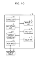
- FIG. 10 is a hardware configuration diagram of an image processing device 1 according to another embodiment.
- the image processing device 1 includes a control unit 10 , a main storage unit 11 , an auxiliary storage unit 12 , a drive device 13 , a network I/F unit 15 , an input unit 16 , and a display unit 17 . These elements are connected with each other so as to be able to mutually transmit and receive data via a bus.
- the control unit 10 is a CPU which performs control of respective elements and calculation and processing of data in a computer. Further, the control unit 10 is an arithmetic device which executes a program which is stored in the main storage unit 11 and the auxiliary storage unit 12 . The control unit 10 receives data from the input unit 16 and the storage device and calculates and processes the data so as to output the data to the display unit 17 , the storage device, and the like.
- the main storage unit 11 is a ROM or a RAM and is a storage device which stores or temporarily saves a program such as an OS which is fundamental software which is executed by the control unit 10 and application software or data.
- the auxiliary storage unit 12 is an HDD or the like and is a storage device which stores data related to application software and the like.
- the drive device 13 reads out a program from a recording medium 14 such as a flexible disk and installs the program on the auxiliary storage unit 12 . Further, a predetermined program is stored in the recording medium 14 and the predetermined program which is stored in the recording medium 14 is installed on the image processing device 1 via the drive device 13 . The predetermined program which is installed is executable by the image processing device 1 .
- the network I/F unit 15 is an interface between peripheral equipment, which is connected via a network, such as a local area network (LAN) and a wide area network (WAN), which is structured by a data transmission path such as a wired and/or wireless line and has a communication function, and the image processing device 1 .
- a network such as a local area network (LAN) and a wide area network (WAN), which is structured by a data transmission path such as a wired and/or wireless line and has a communication function
- LAN local area network
- WAN wide area network
- the input unit 16 includes a keyboard which is provided with cursor keys, digit input keys, various functional keys, and the like and a mouse, a slide pad, and the like for selecting a key on a display screen of the display unit 17 , for example. Further, the input unit 16 is a user interface by which a user provides operation instruction to the control unit 10 and inputs data, for example.
- the display unit 17 is composed of a cathode ray tube (CRT), a liquid crystal display (LCD), or the like and performs display corresponding to display data which is inputted from the control unit 10 .
- CTR cathode ray tube
- LCD liquid crystal display
- the above-described image processing method may be realized as a program for being executed by a computer.
- This program is installed from a server or the like and executed by the computer, being able to realize the above-described image processing method.
- the recording medium 14 various types of recording media such as a recording medium which records information optically, electrically, or magnetically like a CD-ROM, a flexible disk, a magneto-optical disk, or the like and a semiconductor memory which records information electrically like a ROM, a flash memory, or the like may be used.
- respective elements of respective devices which are illustrated in the drawings do not have to be physically configured as illustrated. That is, specific configuration of dispersion and integration of respective devices is not limited to the illustrated configuration, and all or part of the devices may be configured in a manner to be functionally or physically dispersed and integrated in an arbitrary unit in accordance with various types of loads, usage conditions, or the like. Further, various types of processing which have been described in the above embodiments may be realized by executing a prepared program by a computer such as a personal computer and a work station.
Landscapes
- Engineering & Computer Science (AREA)
- Health & Medical Sciences (AREA)
- Biomedical Technology (AREA)
- General Health & Medical Sciences (AREA)
- Multimedia (AREA)
- Signal Processing (AREA)
- Computer Vision & Pattern Recognition (AREA)
- Physics & Mathematics (AREA)
- General Physics & Mathematics (AREA)
- Theoretical Computer Science (AREA)
- Image Analysis (AREA)
- Length Measuring Devices By Optical Means (AREA)
- Image Processing (AREA)
- Closed-Circuit Television Systems (AREA)
- Studio Devices (AREA)
Abstract
Description
I(x,y)=0.299R(x,y)+0.587G(x,y)+0.114B(x,y) (1)
M ij=Σx,y x i y j BW(x,y) (2)
M 00=Σx,y x 0 y 0 BW(x,y)=Σx,y(x,y) (3)
MG ij=Σx,y(x−x G)i(y−y G)j BW(x,y) (5)
S=πab (9)
Claims (11)
Applications Claiming Priority (2)
| Application Number | Priority Date | Filing Date | Title |
|---|---|---|---|
| JP2013-089853 | 2013-04-22 | ||
| JP2013089853A JP6107372B2 (en) | 2013-04-22 | 2013-04-22 | Image processing apparatus, image processing method, and image processing program |
Publications (2)
| Publication Number | Publication Date |
|---|---|
| US20140313349A1 US20140313349A1 (en) | 2014-10-23 |
| US9319669B2 true US9319669B2 (en) | 2016-04-19 |
Family
ID=51728709
Family Applications (1)
| Application Number | Title | Priority Date | Filing Date |
|---|---|---|---|
| US14/167,620 Expired - Fee Related US9319669B2 (en) | 2013-04-22 | 2014-01-29 | Image processing device and image processing method |
Country Status (2)
| Country | Link |
|---|---|
| US (1) | US9319669B2 (en) |
| JP (1) | JP6107372B2 (en) |
Families Citing this family (6)
| Publication number | Priority date | Publication date | Assignee | Title |
|---|---|---|---|---|
| US11004213B2 (en) * | 2016-01-25 | 2021-05-11 | KoreoGRFX, Inc. | Methods and systems for determining motion of a device |
| DE102016205804A1 (en) * | 2016-04-07 | 2017-10-12 | Siemens Aktiengesellschaft | Positioning System |
| JP2018005263A (en) * | 2016-06-27 | 2018-01-11 | Nissha株式会社 | Image processing method, program, photographic paper, and image processing device |
| US10095975B2 (en) * | 2017-03-10 | 2018-10-09 | Capital One Services, Llc | Systems and methods for capturing visible information |
| JP6858742B2 (en) * | 2018-12-17 | 2021-04-14 | 株式会社フジタ | Displacement measuring device |
| CN116109663B (en) * | 2023-04-04 | 2023-06-23 | 山东大学第二医院 | Segmentation method of gastric CT image based on multi-threshold segmentation |
Citations (7)
| Publication number | Priority date | Publication date | Assignee | Title |
|---|---|---|---|---|
| JP2010087743A (en) | 2008-09-30 | 2010-04-15 | Aisin Seiki Co Ltd | Calibrator for on-vehicle camera |
| WO2010050412A1 (en) | 2008-10-28 | 2010-05-06 | 日本電気株式会社 | Calibration index determination device, calibration device, calibration performance evaluation device, system, method, and program |
| JP2010107348A (en) | 2008-10-30 | 2010-05-13 | Panasonic Corp | Calibration target and in-vehicle calibration system using it |
| WO2012001793A1 (en) | 2010-06-30 | 2012-01-05 | 富士通株式会社 | Image processing program and image processing device |
| WO2012061205A1 (en) | 2010-11-02 | 2012-05-10 | Qualcomm Mems Technologies, Inc. | Electromechanical systems apparatuses and methods for providing rough surfaces |
| US20120121127A1 (en) * | 2010-11-12 | 2012-05-17 | Fujitsu Limited | Image processing apparatus and non-transitory storage medium storing image processing program |
| US20120203371A1 (en) * | 2011-02-07 | 2012-08-09 | Vistaprint Technologies Limited | Method and system for converting an image to a color-reduced image mapped to embroidery thread colors |
Family Cites Families (2)
| Publication number | Priority date | Publication date | Assignee | Title |
|---|---|---|---|---|
| JP2006260397A (en) * | 2005-03-18 | 2006-09-28 | Konica Minolta Holdings Inc | Eye opening degree estimating device |
| JP5271742B2 (en) * | 2009-02-10 | 2013-08-21 | セコム株式会社 | Sunglass wear detection device |
-
2013
- 2013-04-22 JP JP2013089853A patent/JP6107372B2/en not_active Expired - Fee Related
-
2014
- 2014-01-29 US US14/167,620 patent/US9319669B2/en not_active Expired - Fee Related
Patent Citations (9)
| Publication number | Priority date | Publication date | Assignee | Title |
|---|---|---|---|---|
| JP2010087743A (en) | 2008-09-30 | 2010-04-15 | Aisin Seiki Co Ltd | Calibrator for on-vehicle camera |
| WO2010050412A1 (en) | 2008-10-28 | 2010-05-06 | 日本電気株式会社 | Calibration index determination device, calibration device, calibration performance evaluation device, system, method, and program |
| US20110199491A1 (en) | 2008-10-28 | 2011-08-18 | Takashi Jikihira | Calibration index determination device, calibration device, calibration performance evaluation device, system, method, and program |
| JP2010107348A (en) | 2008-10-30 | 2010-05-13 | Panasonic Corp | Calibration target and in-vehicle calibration system using it |
| WO2012001793A1 (en) | 2010-06-30 | 2012-01-05 | 富士通株式会社 | Image processing program and image processing device |
| US20130108155A1 (en) * | 2010-06-30 | 2013-05-02 | Fujitsu Limited | Computer-readable recording medium and image processing apparatus |
| WO2012061205A1 (en) | 2010-11-02 | 2012-05-10 | Qualcomm Mems Technologies, Inc. | Electromechanical systems apparatuses and methods for providing rough surfaces |
| US20120121127A1 (en) * | 2010-11-12 | 2012-05-17 | Fujitsu Limited | Image processing apparatus and non-transitory storage medium storing image processing program |
| US20120203371A1 (en) * | 2011-02-07 | 2012-08-09 | Vistaprint Technologies Limited | Method and system for converting an image to a color-reduced image mapped to embroidery thread colors |
Also Published As
| Publication number | Publication date |
|---|---|
| JP2014215645A (en) | 2014-11-17 |
| JP6107372B2 (en) | 2017-04-05 |
| US20140313349A1 (en) | 2014-10-23 |
Similar Documents
| Publication | Publication Date | Title |
|---|---|---|
| US9319669B2 (en) | Image processing device and image processing method | |
| CN101155238B (en) | Image region detection method and device therefor | |
| US8831381B2 (en) | Detecting and correcting skew in regions of text in natural images | |
| KR101292925B1 (en) | Object of image capturing, computer readable media for storing image processing program and image processing method | |
| JP2008217347A (en) | License plate recognition device, control method thereof, computer program | |
| US9141874B2 (en) | Feature extraction and use with a probability density function (PDF) divergence metric | |
| US20140022406A1 (en) | Automatic correction of skew in natural images and video | |
| US20120121127A1 (en) | Image processing apparatus and non-transitory storage medium storing image processing program | |
| US20150055857A1 (en) | Text detection in natural images | |
| US10452943B2 (en) | Information processing apparatus, control method of information processing apparatus, and storage medium | |
| JP5472463B2 (en) | Image processing program and image processing apparatus | |
| US20120140996A1 (en) | Striped pattern image examination support device, striped pattern image examination support method and program | |
| CN104268512A (en) | Method and device for recognizing characters in image on basis of optical character recognition | |
| US7922087B2 (en) | Image processing apparatus, image processing method, and computer program stored in storage medium | |
| JP2013254242A (en) | Image recognition device, image recognition method, and image recognition program | |
| US12169965B2 (en) | Information processing apparatus and information processing method | |
| CN114926328B (en) | Image stitching method, device, processing equipment and storage medium | |
| CN116916170A (en) | Image acquisition device and image acquisition method | |
| US10304195B2 (en) | Information processing apparatus, computer-readable storage medium, and information processing method for judging a recognition target area | |
| JP5397103B2 (en) | Face position detection device, face position detection method, and program | |
| CN104992432A (en) | Multimodal image registration method | |
| JP2015170205A (en) | Feature amount generation device, feature amount generation method, and program | |
| CN115879489A (en) | Method and device for positioning distorted two-dimensional code | |
| JP2000235618A (en) | Character detection device | |
| CN115908373A (en) | Positioning graph detection method and device of quick response code |
Legal Events
| Date | Code | Title | Description |
|---|---|---|---|
| AS | Assignment |
Owner name: FUJITSU LIMITED, JAPAN Free format text: ASSIGNMENT OF ASSIGNORS INTEREST;ASSIGNORS:AOKI, YASUHIRO;MIZUTANI, MASAMI;REEL/FRAME:032107/0724 Effective date: 20140116 |
|
| STCF | Information on status: patent grant |
Free format text: PATENTED CASE |
|
| MAFP | Maintenance fee payment |
Free format text: PAYMENT OF MAINTENANCE FEE, 4TH YEAR, LARGE ENTITY (ORIGINAL EVENT CODE: M1551); ENTITY STATUS OF PATENT OWNER: LARGE ENTITY Year of fee payment: 4 |
|
| FEPP | Fee payment procedure |
Free format text: MAINTENANCE FEE REMINDER MAILED (ORIGINAL EVENT CODE: REM.); ENTITY STATUS OF PATENT OWNER: LARGE ENTITY |
|
| LAPS | Lapse for failure to pay maintenance fees |
Free format text: PATENT EXPIRED FOR FAILURE TO PAY MAINTENANCE FEES (ORIGINAL EVENT CODE: EXP.); ENTITY STATUS OF PATENT OWNER: LARGE ENTITY |
|
| STCH | Information on status: patent discontinuation |
Free format text: PATENT EXPIRED DUE TO NONPAYMENT OF MAINTENANCE FEES UNDER 37 CFR 1.362 |
|
| STCH | Information on status: patent discontinuation |
Free format text: PATENT EXPIRED DUE TO NONPAYMENT OF MAINTENANCE FEES UNDER 37 CFR 1.362 |
|
| FP | Lapsed due to failure to pay maintenance fee |
Effective date: 20240419 |