US9317771B2 - Device and method to detect an object and controlling a device to pick up the detected object - Google Patents
Device and method to detect an object and controlling a device to pick up the detected object Download PDFInfo
- Publication number
- US9317771B2 US9317771B2 US14/184,638 US201414184638A US9317771B2 US 9317771 B2 US9317771 B2 US 9317771B2 US 201414184638 A US201414184638 A US 201414184638A US 9317771 B2 US9317771 B2 US 9317771B2
- Authority
- US
- United States
- Prior art keywords
- points
- endpoint
- starting point
- point
- positions
- Prior art date
- Legal status (The legal status is an assumption and is not a legal conclusion. Google has not performed a legal analysis and makes no representation as to the accuracy of the status listed.)
- Expired - Fee Related, expires
Links
Images


Classifications
-
- G06K9/4633—
-
- G—PHYSICS
- G06—COMPUTING OR CALCULATING; COUNTING
- G06V—IMAGE OR VIDEO RECOGNITION OR UNDERSTANDING
- G06V20/00—Scenes; Scene-specific elements
- G06V20/60—Type of objects
- G06V20/64—Three-dimensional [3D] objects
- G06V20/653—Three-dimensional [3D] objects by matching three-dimensional models, e.g. conformal mapping of Riemann surfaces
-
- G06K9/00214—
-
- G06K9/6211—
-
- G06T7/0046—
-
- G—PHYSICS
- G06—COMPUTING OR CALCULATING; COUNTING
- G06T—IMAGE DATA PROCESSING OR GENERATION, IN GENERAL
- G06T7/00—Image analysis
- G06T7/70—Determining position or orientation of objects or cameras
- G06T7/73—Determining position or orientation of objects or cameras using feature-based methods
- G06T7/75—Determining position or orientation of objects or cameras using feature-based methods involving models
-
- G—PHYSICS
- G06—COMPUTING OR CALCULATING; COUNTING
- G06V—IMAGE OR VIDEO RECOGNITION OR UNDERSTANDING
- G06V10/00—Arrangements for image or video recognition or understanding
- G06V10/40—Extraction of image or video features
- G06V10/48—Extraction of image or video features by mapping characteristic values of the pattern into a parameter space, e.g. Hough transformation
-
- G—PHYSICS
- G06—COMPUTING OR CALCULATING; COUNTING
- G06V—IMAGE OR VIDEO RECOGNITION OR UNDERSTANDING
- G06V10/00—Arrangements for image or video recognition or understanding
- G06V10/70—Arrangements for image or video recognition or understanding using pattern recognition or machine learning
- G06V10/74—Image or video pattern matching; Proximity measures in feature spaces
- G06V10/75—Organisation of the matching processes, e.g. simultaneous or sequential comparisons of image or video features; Coarse-fine approaches, e.g. multi-scale approaches; using context analysis; Selection of dictionaries
- G06V10/757—Matching configurations of points or features
Definitions
- the embodiments discussed herein are directed to an object detecting method and an object detecting device.
- Japanese Patent No. 5088278 discloses an object detecting method in which a distance from a distance sensor to a point located on an edge of an object is subjected to Hough transform to cast votes in Hough spaces and the position and the attitude of the object are detected based on the point having the largest number of votes in the Hough spaces.
- An object detecting method includes: setting a plurality of external reference points used as information for estimating a position and an attitude of an object in external space of a model of the object, and setting an internal reference point used as information for determining whether the information for estimation is valid in internal space of the model; storing a table in which feature quantities on a local surface including a pair of a starting point and an endpoint that are sequentially selected from a, point group located on a surface of the model are associated with a set of positions of the external reference points and the internal reference point with respect to the starting point; sequentially selecting a pair of a starting point and an endpoint from a sample point group located on a surface of the object existing in real space, and calculating feature quantities of the object on a local surface including the pair of the starting point and the endpoint; and acquiring, from the table, the set of positions associated with feature quantities matching the feature quantities of the object, transforming this set into a set of positions in the real space, and when the position of the internal reference point in the
- FIG. 1A and FIG. 1B are diagrams illustrating an object detecting method according to an embodiment.
- FIG. 2 is a diagram illustrating a robot system according to the embodiment.
- FIG. 3 is a diagram illustrating one example of configuration of an object detecting device according to the embodiment.
- FIGS. 4A, 4B, 5A, 5B, and 6 are diagrams illustrating a procedure for preparing a table according to the embodiment.
- FIG. 7 is a diagram illustrating one example of the table according to the embodiment.
- FIGS. 8A, 8B, 9, and 10 are diagrams illustrating a procedure for detecting the position and the attitude of an object according to the embodiment.
- FIG. 11 is a flowchart illustrating a process of preparing a table according to the embodiment.
- FIG. 12 is a flowchart illustrating a process of detecting the positions and the attitudes of objects according to the embodiment.
- FIG. 13 is a flowchart illustrating a process of preparing information on candidates to be held according to the embodiment.
- Embodiments of an object detecting method and an object detecting device disclosed in the present application will now be described in detail with reference to the accompanying drawings. It should be noted that the present invention is not limited by the embodiments described below. A case where the shape of an object whose position and attitude are to be detected is a cylindrical shape will be described below as an example, but the shape of the object to be detected is not limited to the cylindrical shape.
- FIG. 1A and FIG. 1B are diagrams illustrating an object detecting method according to an embodiment.
- information indicating a surface shape of a model M is acquired.
- the model M has the same shape as that of the object to be detected and the position and the attitude of the model M in real space are known.
- the information on each point of a point group located on a surface of the model M is acquired.
- the information on each point includes three-dimensional position information (position vector) in the real space for each point and information on a normal vector with respect to the surface of the model M at each point.
- a plurality of external reference points O 1 , O 2 , and O 3 used as information for estimating the position and the attitude of the object are set in external space of the model M, and an internal reference point O 4 used as information for determining whether the information for estimating the position and the attitude of the object is valid is set in internal space of the model M.
- the number of the reference points thus set is not limited to this.
- Feature quantities of a local surface of the model M including a pair of a starting point P i and an endpoint P j that are sequentially selected from the point group located on the surface of the model M are calculated. These feature quantities are, for example, the distance between the starting point P i and the endpoint P j , the inner product between normal lines at the starting point P i and at the endpoint P j , and the inner product between the normal line at the starting point P i and a vector connecting the starting point P i and the endpoint P j .
- a table in which the feature quantities thus calculated are associated with a set of position vectors of the external reference points O 1 , O 2 , and O 3 and the internal reference point O 4 , with respect to the starting point P i (see arrows from the starting point P i to the external reference points O 1 , O 2 , and O 3 and the internal reference point O 4 ) is prepared and stored. These steps are performed off-line in advance before the position and the attitude of an object existing in the real space are detected.
- the information indicating the surface shape of the surface of an object W includes three-dimensional position information (position vector) in the real space for a sample point group located on the surface of the object W.
- a pair of a starting point P (i) and an endpoint P (j) is sequentially selected from the sample point group, feature quantities of the object W at a local surface including the pair of the starting point P (i) and the endpoint P (j) are calculated, and a set of a plurality of position vectors with which feature quantities matching the feature quantities of the object W are associated is acquired from the table previously stored.
- the correct positions of reference points of the object W can be acquired by transforming the set of the acquired position vectors into position vectors in the real space. Accordingly, based on three position vectors thus transformed, the correct position and attitude of the object W can be estimated and detected.
- the position of the starting point P i of the position vectors in the model M acquired from the table may not match the position of the starting point P (i) in the object W selected from the sample group.
- feature quantities of a local surface in the object W may match feature quantities of a local surface in the model M even when the position of the starting point P (i) in the object W differs from the position of the starting point P i in the model M.
- Hough transform is used to transform a plurality of sets of position vectors acquired from the table into sets of position vectors in the real space, and votes are cast for voting points in the real space being Hough space that correspond to three-dimensional positions indicated by the transformed position vectors.
- position vectors in the set of voting points having the largest number of votes obtained is determined to be the correct positions of the reference points of the object W, and the position and the attitude of the object W is determined based on these positions.
- the sets of position vectors acquired from the table contain a position vector that is inappropriate as information for estimating the position and the attitude of the object W.
- a voting point for such a position vector that is inappropriate as information for estimating the position and the attitude may receive votes more than the number of voting points for appropriate position vectors, and thus the accuracy of detecting the position and the attitude of the object W may decrease.
- the object detecting method by excluding sets of position vectors that are inappropriate as information for estimating the position and the attitude from sets to be voted for before casting votes, the detection accuracy is improved with a reduced amount of processing required for detecting the position and the attitude of the object.
- the three points A, B, and C in the real space contained in the same set as that of the point D are excluded from points to be voted for, i.e., from information for estimating the position and the attitude of the object W.
- the object detecting method before votes are cast, a set of position vectors that are inappropriate as information for estimating the position and the attitude can be excluded from sets to be voted for, whereby the detection accuracy is improved with a reduced amount of processing required for detecting the position and the attitude of the object W.
- FIG. 2 is a diagram illustrating this robot system 1 according to the embodiment.
- the robot system 1 includes a robot 2 , a sensor 3 , this object detecting device 4 , and a robot control device 5 .
- the robot 2 includes a torso portion 21 mounted, for example, on a floor, and a right arm 22 and a left arm 23 that stretch from the torso portion 21 .
- the right arm 22 and the left arm 23 are robot arms each having seven-axis degrees of freedom.
- a hand 24 for holding a box 6 in which cylindrical objects W are stored in bulk is provided at the end of the right arm 22
- a hand 25 for picking up the objects W from the inside of the box 6 is provided at the end of the left arm 23 .
- the sensor 3 is a sensor for detecting the three-dimensional shape of the objects W stored in bulk in the box 6 , and is a three-dimensional scanner, for example.
- the sensor 3 is supported by a support 31 and arranged vertically above the box 6 .
- the sensor 3 scans the object W with a laser beam to detect the three-dimensional shape of the objects W on the basis of the reflected beam reflected from the objects W.
- the sensor 3 outputs information indicating the three-dimensional shape of the objects W (hereinafter, referred to as “scene data”) to the object detecting device 4 .
- the scene data includes the above-described three-dimensional position information (position vector) in the real space for the sample point group located on the surface of the object W.
- the object detecting device 4 detects the positions and the attitudes of the objects W stored in bulk in the box 6 on the basis of scene data input from the sensor 3 and the above-described table, and outputs the position and the attitude of an object W to be held by the robot 2 to the robot control device 5 .
- One example of configuration of the object detecting device 4 will be described later with reference to FIG. 3 .
- the robot control device 5 generates a control signal for the robot 2 on the basis of the position and the attitude of the object W to be held input from the object detecting device 4 , and causes the robot 2 to perform operation of picking up the object W by outputting the control signal to the robot 2 .
- FIG. 3 is a diagram illustrating the example of configuration of the object detecting device 4 according to the embodiment.
- the object detecting device 4 includes a processing unit 7 and a storage unit 8 .
- the storage unit 8 stores a table 81 described above.
- One example of the table 81 will described later with reference to FIG. 7 .
- the processing unit 7 includes a model data acquisition unit 71 , a scene data acquisition unit 72 , a reference point setting unit 73 , an edge detecting unit 74 , a surflet selecting unit 75 , a calculating unit 76 , a position/attitude estimating unit 77 , and a holding-target information generating unit 78 .
- the object detecting device 4 causes the model data acquisition unit 71 , the reference point setting unit 73 , the edge detecting unit 74 , the surflet selecting unit 75 , and the calculating unit 76 to prepare the table 81 described above, and causes the storage unit 8 to store the table 81 .
- FIGS. 4A, 4B, 5A, 5B, 6, and 7 are diagrams illustrating the procedure for preparing the table 81 according to the embodiment
- FIG. 7 is a diagram illustrating the example of the table 81 according to the embodiment.
- the model data acquisition unit 71 reads CAD data of the model M depicted in FIG. 4A whose size and shape are the same as those of the object W to be held by the robot 2 from a predetermined information processing device (not depicted). The model data acquisition unit 71 then extracts and acquires model data indicating the surface shape of the model M from the CAD data.
- the model data acquisition unit 71 acquires, as depicted in FIG. 4B , three-dimensional position information (position vector) in the real space for each point of a point group located on a surface of the model M and information of normal vectors with respect to the surface of the model M at each point, for example, as model data.
- the model data acquisition unit 71 then outputs the model data thus acquired to the reference point setting unit 73 .
- the reference point setting unit 73 sets three external reference points O 1 , O 2 , and O 3 in external space of the model M for the model data, and also sets an internal reference point O 4 in internal space of the model M as depicted in FIG. 4B .
- the external reference points O 1 , O 2 , and O 3 and the internal reference point O 4 are not distinguished from each other, these are collectively referred to as reference points O.
- the reference point setting unit 73 outputs the model data provided with the reference points O to the edge detecting unit 74 .
- the edge detecting unit 74 detects edges Ed of the model M on the basis of the model data input from the reference point setting unit 73 as depicted in FIG. 5A . Furthermore, the edge detecting unit 74 adds, to a point group forming the edges Ed of the model M, information indicating that points thereof are on the edges Ed (hereinafter, referred to as “label E”). The edge detecting unit 74 also adds, to a point group forming a portion other than the edges Ed of the model M, information indicating that points thereof are on a face (hereinafter, referred to as “label F”). The edge detecting unit 74 then outputs the model data to which the label E and the label F are added to the surflet selecting unit 75 .
- the surflet selecting unit 75 sequentially selects pairs of two points located on the surface of the model M as a pair of a starting point P i and an endpoint P j from the model data input from the edge detecting unit 74 to acquire information on the points thus selected (hereinafter, referred to as “surflet”).
- the surflet selecting unit 75 acquires a set of a position vector p i , the label F, and a normal vector n i in the real space for the starting point P i as a surflet ⁇ (p i ) of the starting point P i .
- the surflet selecting unit 75 acquires a set of a position vector p j in the real space for the endpoint P j , the label E, and a gradient vector g j for the endpoint P j as a surflet ⁇ (p j ) of the endpoint P j .
- the gradient vector g j herein is an angle between the circumferential surface and an end surface of the model M at the endpoint P j .
- the surflet selecting unit 75 acquires a set of the position vector of the endpoint, the label F, and the normal vector at the endpoint as a surflet of the endpoint.
- the surflet selecting unit 75 while changing the starting point P i and the endpoint P j to be selected, acquires a plurality of pairs of the surflet ⁇ (p i ) and the surflet ⁇ (p j ) (hereinafter, referred to as “surflet pairs”), and outputs the surflet pairs to the calculating unit 76 .
- the surflet pairs are information used for, for example, a process in which the calculating unit 76 calculates feature quantities of a local surface of the model M including the pair of the starting point P i and the endpoint P j .
- the surflet selecting unit 75 may be configured to select all points located on the surface of the model M as the starting point P i and the endpoint P j to acquire the surflet pairs, or may be configured to select points to which the label E is added or points to which the label F is added as the endpoint P j .
- the configuration to exclusively select points to which the label E is added as the endpoint P j is effective when an area occupied by a plane portion is relatively large in a model. More specifically, in such a model in which a large area is occupied by a plane portion, selecting any points in the plane portion as the starting point P i and the endpoint P j makes little difference, and selecting the edge Ed portion as the endpoint P j can provide feature quantities that represent the features of the model more precisely. Furthermore, points on the face to which the label F is added can be excluded from candidates for the endpoint P j , whereby the amount of processing for calculating the feature quantities can be reduced.
- the configuration to exclusively select points to which the label F is added as the endpoint P j is effective when an area occupied by a curved surface in a model is relatively large. More specifically, in such a model in which a large area is occupied by a curved surface, each of local planes on a face of the model has features of the model.
- the calculating unit 76 uses the surflet pairs input from the surflet selecting unit 75 to calculate feature quantities of local surfaces of the model M including the pair of the starting point P i and the endpoint P j .
- the calculating unit 76 calculates the following feature quantities: the distance between the starting point P i and the endpoint P j ; the inner product of a normal vector n i at the starting point P i and a normal vector n j at the endpoint P j ; and the inner product between the normal vector n i at the starting point P i and a vector f i,j connecting the starting point P i and the endpoint P j .
- the calculating unit 76 calculates a local coordinate system having the starting point P i as the origin to calculate position vectors of the reference points O in the local coordinate system (see dashed-dotted arrows depicted in FIG. 5B ).
- a position vector p i of the starting point P i a position vector p j of the endpoint P j , and a difference vector f i,j between the position vector p i and the position vector p j are used.
- the position vectors of the respective reference points O in the real space can be expressed by the following formula (1).
- the position vectors of the respective reference points O in the real space are expressed by using a local coordinate system defined by ⁇ p i , n i , f i,j >.
- the local coordinate system is defined as follows.
- e 1 ( i , j ) n 1 ⁇ n i ⁇ ( 2 )
- e 2 ( i , j ) n i ⁇ f i , j ⁇ n i ⁇ f i , j ⁇ ( 3 )
- e 3 ( i , j ) e 2 ( i , j ) ⁇ n i ⁇ e 2 ( i , j ) ⁇ n i ⁇ ( 4 )
- the position vectors in the local coordinate system for the respective reference points O are calculated by the following formula (5).
- the calculating unit 76 prepare the table 81 in which a feature quantity (H 1 , H 2 , etc.) of a local surface including the pair of starting point P i and the endpoint P j previously calculated and the set of position vectors of the reference points O (herein, four position vectors of the external reference points O 1 , O 2 , and O 3 and the internal reference point O 4 ) in a local coordinate system having the starting point P i as the origin are associated as depicted in FIG. 7 .
- a feature quantity (H 1 , H 2 , etc.) of a local surface including the pair of starting point P i and the endpoint P j previously calculated and the set of position vectors of the reference points O herein, four position vectors of the external reference points O 1 , O 2 , and O 3 and the internal reference point O 4 ) in a local coordinate system having the starting point P i as the origin are associated as depicted in FIG. 7 .
- the model M has a plurality of local surfaces whose feature quantities are the same. Accordingly, in the table 81 , a plurality of sets of the reference points O in the local coordinate system each are associated with one feature quantity (H 1 , H 2 , etc.), that is, the table 81 has a data structure of a hash table containing each feature quantity (H 1 , H 2 , etc.) as a key.
- the calculating unit 76 causes the storage unit 8 to store the table 81 thus formed.
- the object detecting device 4 estimates and detects the position and the attitude of the object W with the scene data acquisition unit 72 , the edge detecting unit 74 , the surflet selecting unit 75 , the calculating unit 76 , the position/attitude estimating unit 77 , and the holding-target information generating unit 78 .
- FIGS. 8A, 8B, 9, and 10 are diagrams illustrating a procedure for detecting the position and the attitude of the object W according to the embodiment.
- the scene data acquisition unit 72 acquires scene data indicating the three-dimensional shape of objects W stored in bulk as depicted in FIG. 8A from the sensor 3 . More specifically, the scene data acquisition unit 72 acquires three-dimensional position information (position vector) in the real space for each point of a sample point group located on a surface of an object W and information of a normal vector n (i) with respect to the surface of the object W for each point, for example, as depicted in FIG. 813 as scene data. The scene data acquisition unit 72 then outputs the scene data thus acquired to the edge detecting unit 74 .
- position vector position vector
- n normal vector
- the edge detecting unit 74 detects edges of the object W on the basis of the scene data input from the scene data acquisition unit 72 . Furthermore, the edge detecting unit 74 adds, to a sample point group forming the edges of the object W, the label E indicating that points thereof are on the edges, and calculate a gradient vector g (j) of each sample point to which the label E is added.
- the edge detecting unit 74 also adds, to a sample point group forming a portion other than the edges of the object W, the label F indicating that points thereof are on a face. The edge detecting unit 74 then outputs model data to which the label E and the label F are added to the surflet selecting unit 75 . The edge detecting unit 74 also outputs the gradient vector g (j) of each sample point on the edges to the surflet selecting unit 75 .
- the surflet selecting unit 75 sequentially selects a pair of two points located on a surface of the object W as a pair of a starting point P (i) and an endpoint P (j) , and acquires surflets on the sample points thus selected.
- the surflet selecting unit 75 acquires a set of a position vector p (i) , the label F, and a normal vector n (i) in the real space for the starting point P (i) as a surflet ⁇ (p i ) of the starting point P (i) .
- the surflet selecting unit 75 acquires a position vector p (j) in the real space for the endpoint P (j) , the label E, and a gradient vector g (j) of the endpoint P (j) as a surflet ⁇ (p j ) of the endpoint P (j) .
- the gradient vector g (j) herein is an angle between the circumferential surface and an end surface of the object W at the endpoint P (j) .
- the surflet selecting unit 75 acquires a set of the position vector of the endpoint, the label F, and the normal vector at the endpoint as a surflet of the endpoint.
- the surflet selecting unit 75 while changing the starting point P (i) and the endpoint P (j) to be selected, acquires surflet pairs that are a plurality of pairs of the surflet ⁇ (p i ) and the surflet ⁇ (p j ), and outputs the surflet pairs to the calculating unit 76 .
- the surflet pairs are information used for, for example, a process in which the calculating unit 76 calculates feature quantities of a local surface of the object W including the pair of the starting point P (i) and the endpoint P (j) . Accordingly, similarly to the case of acquiring the surflet pairs of the model M, by selecting all points as the starting point P (i) and the endpoint P (j) to acquire the surflet pairs, the accuracy of detecting the object W can be improved.
- the surflet selecting unit 75 exclusively selects the endpoint P j to which the label E is added, whereby the accuracy of detecting the position and the attitude of the object can be improved with a reduced amount of processing for an object in which a large area is occupied by a plane portion.
- the surflet selecting unit 75 exclusively selects the P j to which the label F is added, whereby the accuracy of detecting the position and the attitude of the object can be improved for an object in which a large area is occupied by a curved surface.
- the calculating unit 76 uses the surflet pairs input from the surflet selecting unit 75 to calculate feature quantities of local surfaces of the object W including the pair of the starting point P (i) and the endpoint P (j) .
- the calculating unit 76 calculates the following feature quantities: the distance between the starting point P (i) and the endpoint P (j) ; the inner product of a normal vector n (i) at the starting point P (i) and a normal vector n (j) at the endpoint P (j) ; and the inner product between the normal vector n (i) at the starting point P (i) and a vector f (i,j) connecting the starting point P (i) and the endpoint P (j) .
- the calculating unit 76 then outputs the surflet pairs used to calculate the feature quantities and the feature quantities of local surfaces of the object W calculated to the position/attitude estimating unit 77 .
- the position/attitude estimating unit 77 acquires from the table 81 a plurality of sets of position vectors of the reference points O with which feature quantities matching the feature quantities of local surfaces of the object W input from the calculating unit 76 are associated. Furthermore, the position/attitude estimating unit 77 calculates a local coordinate system having the starting point P (i) as the origin. The position/attitude estimating unit 77 then transforms the sets of position vectors acquired from the table 81 into sets of position vectors in the local coordinate system having the starting point P (i) as the origin by the following formula (6).
- ⁇ circumflex over (d) ⁇ i,j k a i,j k ê 1 (i,j) +b i,j k ê 2 (i,j) +c i,j k ê 3 (i,j) (6)
- the position/attitude estimating unit 77 transforms the sets of transformed position vectors in the local coordinate system having the starting point P (i) as the origin into sets of position vectors in the real space by the following formula (7).
- position vectors in the real space for external reference points O 5 , O 6 , and O 7 and an internal reference point O 8 are calculated.
- the position/attitude estimating unit 77 determines whether the external reference points O 5 , O 6 , and O 7 are valid based on the positional relation between sample points on the surface of the object W indicated by filled circles and the internal reference point O 8 indicated by open circles as depicted in FIG. 9 .
- the X-axis and Y-axis depicted in FIG. 9 are orthogonal vectors located on a plane parallel to the horizontal plane, and the Z-axis is orthogonal to the XY plane and the positive direction thereof is the vertical downward direction.
- the position/attitude estimating unit 77 determines that the position vectors of the external reference points O 5 , O 6 , and O 7 in the same set as that of the position vector of the internal reference point O 8 are appropriate reference points as information for estimating the position and the attitude of the object W.
- the position/attitude estimating unit 77 determines that the external reference points in the same set as that of the position vector of the internal reference point O 9 are inappropriate reference points as information for estimating the position and the attitude of the object W to exclude these external reference points from information for estimation.
- the position/attitude estimating unit 77 verifies whether the internal reference point O 8 is inside the object W by the following formula (8) to determine whether the external reference points O 5 , O 6 , and O 7 are valid.
- scanZ(x,y) in the above formula (8) is a z-coordinate value of a sample point whose x-coordinate value and y-coordinate value in the real space match the x-coordinate value and the y-coordinate value of the internal reference point O 8 .
- the position/attitude estimating unit 77 excludes reference points O that are inappropriate as information for estimating the position and the attitude of the object W from the information for estimating the position and the attitude of the object W. Accordingly, the position/attitude estimating unit 77 can improve the accuracy of estimating the position and the attitude of the object W while reducing the amount of processing for casting votes for the external reference points O 5 , O 6 , and O 7 performed later.
- the internal reference point O 4 is set in the internal space of the model M in the present embodiment, the internal reference point O 4 may be set on the surface of the model M, for example, other than the internal space of the model M.
- the validity criterion may be so severe that the appropriate reference points O can be mistakenly determined to be inappropriate.
- a certain threshold th is set in the above formula (8) and a certain margin is kept in the validity criterion for the external reference points O 5 , O 6 , and O 7 , whereby occurrence of misjudgment in which appropriate reference points are determined to be inappropriate is suppressed.
- the position/attitude estimating unit 77 performs a process of casting votes for respective voting points in the real space that match the positions in the real space for the external reference points O 5 , O 6 , and O 7 that are determined to be appropriate as information for determining the position and the attitude of the object W.
- the position/attitude estimating unit 77 casts votes for three points A 1 , B 1 , and C 1 in the real space depicted in the lower diagram of FIG. 10 corresponding to the external reference points O 5 , O 6 , and O 7 , respectively, in the local coordinate having the starting point P (i) as the origin depicted in the upper diagram of FIG. 10 .
- the position/attitude estimating unit 77 sequentially casts votes in the real space.
- the number of votes obtained for the set of three voting points A 1 , B 1 , and C 1 depicted in FIG. 10 gradually increases.
- votes are sequentially cast for respective sets of other three voting points in the real space, for each set of three external reference points.
- the position/attitude estimating unit 77 monitors the number of votes obtained for the respective voting points, for each set of these three voting points.
- the position/attitude estimating unit 77 casts votes for each set of three voting points independent in the three-dimensional real space that correspond to the positions of the respective external reference points in each set of three external reference points. Accordingly, the amount of calculation required for the voting can be significantly reduced. However, in the position/attitude estimating unit 77 , what is called an interference phenomenon occurs in which, among three votes that should be originally cast for one set of three voting points, any one vote is cast for another set of voting points.
- the position/attitude estimating unit 77 lists the sets of three voting points. The position/attitude estimating unit 77 then sums up the number of total votes obtained for each set of three voting points thus listed, and estimates the position and the attitude of the object W in order from the set obtaining the largest number of votes on the basis of the positions in the real space for voting points in the set.
- the position/attitude estimating unit 77 lists the set of three points A 1 , B 1 , and C 1 . Accordingly, for example, even if the numbers of votes obtained for the two points B 1 and C 1 increase, unless the number of votes obtained for the point A 1 has reached the threshold Vth, the set of three points A 1 , B 1 , and C 1 validity of which is not determined yet can be prevented from being prematurely determined to be a set of appropriate voting points.
- the position/attitude estimating unit 77 outputs information indicating the positions and the attitudes of a plurality of objects W estimated to the holding-target information generating unit 78 .
- the holding-target information generating unit 78 determines whether an object W that can be a candidate to be held by the robot 2 is present. When a candidate to be held is present, the holding-target information generating unit 78 outputs information indicating the position and the attitude of the candidate to be held to the robot control device 5 . When no candidate to be held is present, the holding-target information generating unit 78 outputs information indicating absence of a candidate to the robot control device 5 .
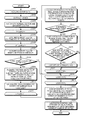
- FIG. 11 is a flowchart illustrating a process of preparing the table 81 according to the embodiment.
- FIG. 12 is a flowchart illustrating a process of detecting the positions and the attitudes of objects W according to the embodiment.
- FIG. 13 is a flowchart illustrating a process of preparing information on candidates to be held according to the embodiment.
- the processing unit 7 of the object detecting device 4 prepares the table 81 by performing the process depicted in FIG. 11 in advance before detecting the position and the attitude of an object W. More specifically, the processing unit 7 acquires model data first (step S 101 ), and extracts edges Ed of the model M from the model data (step S 102 ).
- the processing unit 7 sets a variable i that corresponds to a position on a surface of the model M for a starting point P i selected from the surface of the model M to one (step S 103 ).
- the processing unit 7 then sets a variable j that corresponds to a position on the surface of the model M for an endpoint P j selected from the surface of the model M to one (step S 104 ).
- the processing unit 7 determines whether the value of the variable i is unequal to the value of the variable j (step S 105 ), that is, the processing unit 7 determines whether the starting point P i and the endpoint P j selected from the surface of the model M are the same point.
- both the value of the variable i and the value of the variable j are one. Accordingly, the processing unit 7 determines that the starting point P i and the endpoint P j are the same point (No at step S 105 ), and moves on to the process at step S 109 .
- step S 109 the processing unit 7 performs the process at the beginning of a loop for the variable j, i.e., step S 104 .
- step S 104 the processing unit 7 adds one to the value of the variable j, and moves on to the process at step S 105 .
- step S 109 the processing unit 7 adds one to the variable j at step S 104 and moves on to the process at step S 110 when the process proceeds to step S 109 after the value of the variable j has reached M j . That is, the processing unit 7 selects a number M j of endpoints P j from the surface of the model M.
- the processing unit 7 moves on to the process at step S 106 .
- the processing unit 7 calculates a local coordinate system having the starting point P i as the origin from the position vector p i of the starting point P i , the normal vector n i at the starting point P i , and the position vector p j of the endpoint P j .
- the processing unit 7 calculates the position vectors of respective reference points O in the local coordinate system thus calculated (step S 107 ).
- the processing unit 7 also calculates feature quantities of a surflet pair ⁇ (p j ), ⁇ (p i )> that are feature quantities of the local surface of the model M including the starting point p i and the endpoint P j .
- the processing unit 7 stores the position vectors of the reference points O calculated in the table 81 in which the feature quantities of the surflet pair ⁇ (p j ), ⁇ (p i )> are set as keys (step S 108 ), and moves on to the process at step S 109 .
- the processing unit 7 then repeats processes of step S 104 to step S 109 for one starting point P i and a number M j of endpoints P j , and then moves on to the process at step S 110 .
- step S 110 the processing unit 7 performs the process at the beginning of a loop for the variable i, i.e., step S 103 .
- step S 103 the processing unit 7 adds one to the variable i, and moves on to the process at step S 104 .
- step S 110 every time the process proceeds to step S 110 , the processing unit 7 adds one to the variable i at step S 103 and moves on to the process at step S 111 when the process proceeds to step S 110 after the value of the variable i has reached M i .
- the processing unit 7 selects a number M i of starting points P i from the surface of the model M, repeats processes of step S 103 to step 110 for each of a number M i of starting points P i and a number M j of endpoints P j , and moves on to the process at step S 111 .
- the processing unit 7 finally stores the table 81 prepared in the storage unit 8 , and ends the process.
- the table 81 may be prepared by a device other than the object detecting device 4 .
- the object detecting device 4 acquires the table 81 prepared from the other device, and stores the table 81 in the storage unit 8 .
- the processing unit 7 also performs surface matching for detecting the positions and the attitudes of objects W by performing the process depicted in FIG. 12 . More specifically, the processing unit 7 acquires scene data of objects W stored in bulk from the sensor 3 first (step S 201 ), and extracts edges of each of the objects W from the scene data (step S 202 ).
- the processing unit 7 calculates normal vectors of respective sample points from the scene data.
- the processing unit 7 also calculates gradient vectors for sample points forming the edges (step S 203 ).
- the processing unit 7 sets a variable i that corresponds to a position on a surface of the object W for a starting point P (i) selected from the surface of the object W to one (step S 204 ), and acquires a surflet ⁇ (p i ) of the starting point P (i) from the scene data (step S 205 ).
- the processing unit 7 sets a variable j that corresponds to a position on the surface of the object W for an endpoint P (j) selected from the surface of the object W to one (step S 206 ), and acquires a surflet ⁇ (p j ) of the endpoint P (j) from the scene data (step S 207 ).
- the processing unit 7 determines whether the surflet pair ⁇ (p j ), ⁇ (p i )> thus acquired satisfies a constraint condition (step S 208 ). For example, in the case that both the starting point P (j) and the endpoint P (j) are points on a face, the processing unit 7 determines that the constraint condition is satisfied when the angle between the normal vector n (i) at the starting point P (i) and the normal vector n (j) at the endpoint P (j) is larger than a certain threshold T f .
- the processing unit 7 determines that the constraint condition is not satisfied when the angle between the normal vector n (i) at the starting point P (i) and the normal vector n (j) at the endpoint P (j) is equal to or smaller than the certain threshold T f .
- the processing unit 7 determines that the constraint condition is satisfied when the angle between the normal vector n (i) at the starting point P (i) and the gradient vector g (j) of the endpoint P (j) is larger than a certain threshold T e .
- the processing unit 7 determines that the constraint condition is not satisfied when the angle between the normal vector n (i) at the starting point P (i) and the gradient vector g (j) of the endpoint P (j) is equal to or smaller than the certain threshold T e .
- the processing unit 7 can be prevented from uselessly acquiring the surflet pair ⁇ (p j ), ⁇ (p i )> for a pair of a starting point P (i) and an endpoint P (j) whose distinctive features are not likely to appear, and thus can reduce the amount of processing.
- the processing unit 7 moves on to the process at step S 209 .
- the processing unit 7 moves on to the process at step S 218 .
- the processing unit 7 acquires, from the table 81 , sets of position vectors of reference points O of all surflet pairs (Nv pairs) whose feature quantities match those of the surflet pair ⁇ (p j ), ⁇ (p i )> acquired at step S 205 and step S 207 .
- the processing unit 7 calculates a local coordinate system of the surflet pair ⁇ (p j ), ⁇ (p i )> acquired at step S 205 and step S 207 (step S 210 ), that is, the processing unit 7 calculates a local coordinate system having the starting point P (i) as the origin on the basis of the surflet pair ⁇ (p j ), ⁇ (p i )>.
- the processing unit 7 sets a variable r that indicates the acquisition order of the sets of position vectors acquired at step S 209 to one (step S 211 ). Subsequently, the processing unit 7 calculates sets of position vectors in the real space for respective reference points O on the basis of the local coordinate system calculated at step S 210 and the set of position vectors of the r-th reference points O (step S 212 ).
- the processing unit 7 determines whether the internal reference point O 8 is inside the object W (step S 213 ). When determining that the internal reference point O 8 is inside the object W (Yes at step S 213 ), the processing unit 7 moves on to the process at step S 214 . When determining that the internal reference point O 8 is outside the object W (No at step S 213 ), the processing unit 7 moves on to the process at step S 217 .
- the processing unit 7 casts votes for voting points in the real space that match the position vectors of the external reference points O 5 , O 6 , and O 7 in the same set as that of the internal reference point O 8 that is determined to be inside the object W at step S 213 .
- the processing unit 7 determines whether the number of votes obtained for a voting point that obtains the smallest number of votes among the set of three voting points for which votes are cast at step S 214 has reached the threshold Vth (step S 215 ).
- the processing unit 7 moves on to the process at step S 216 , lists the set of three voting points for which votes are cast at step S 214 (step S 216 ), and moves on to the process at step S 217 .
- the processing unit 7 moves on to the process at step S 217 .
- step S 217 the processing unit 7 performs the process at the beginning of a loop for the variable r, i.e., step S 211 .
- step S 211 the processing unit 7 adds one to the value of the variable r.
- the processing unit 7 adds one to the value of the variable r at step S 211 , and when the process proceeds to step S 217 after the value of the variable r has reached Nv, moves on to the process at step S 218 , that is, the processing unit 7 performs processes of step S 212 to step S 216 on all sets of position vectors of reference points O acquired at step S 209 .
- step S 218 the processing unit 7 performs the process at the beginning of a loop for a variable j, i.e., step S 206 .
- step S 206 the processing unit 7 adds one to the value of the variable j.
- the processing unit 7 adds one to the value of the variable j at step S 206 and moves on to the process at step S 219 when the process proceeds to step S 218 after the value of the variable j has reached Nh.
- step S 219 the processing unit 7 performs the process at the beginning of a loop for a variable i, i.e., step S 204 .
- step S 204 the processing unit 7 adds one to the value of the variable i.
- the processing unit 7 adds one to the value of the variable i at step S 204 and moves on to the process at step S 220 when the process proceeds to step S 219 after the value of the variable i has reached Nt.
- the processing unit 7 sums up the number of total votes obtained for each set of voting points listed, and sorts the sets of voting points in the descending order of the number of the total votes obtained. Subsequently, the processing unit 7 calculates the positions and the attitudes of objects W from a number G of sets obtaining the largest number of total votes (step S 221 ), and ends the process.
- the processing unit 7 also performs the process depicted in FIG. 13 , thereby generating information on objects W being candidates to be held by the robot 2 , and outputs the information to the robot control device 5 . More specifically, the processing unit 7 measures scene data first as depicted in FIG. 13 (step S 301 ).
- the processing unit 7 detects a number G of candidates to be held calculated by a process (surface matching) depicted in FIG. 12 (step S 302 ). The processing unit 7 then sets a variable t that indicates the order in which detail matching described later is performed on candidates to be held to one (step S 303 ), and moves on to the process at step S 304 . At step S 304 , the processing unit 7 determines whether the value of the variable t is not more than G.
- the processing unit 7 moves on to the process at step S 305 .
- the processing unit 7 sets a flag of no candidates to the robot control device 5 (step S 310 ), and ends the process.
- the processing unit 7 performs the detail matching on the t-th candidate to be held. For example, the processing unit 7 performs detail pattern matching by an iterative closest point (ICP) algorithm for the detail matching. The processing unit 7 then determines whether the detail matching is successful (step S 306 ).
- ICP iterative closest point
- step S 306 when determining that the detail matching is successful (Yes at step S 306 ), the processing unit 7 moves on to the process at step S 307 .
- the processing unit 7 moves on to the process at step S 311 .
- the processing unit 7 performs a hand-interference check to check whether the robot 2 performs picking operation on a candidate to be held without interference by the hand 25 .
- the processing unit 7 determines whether the robot 2 operates without interference (step S 308 ). When determining that the robot 2 operates without interference (Yes at step S 308 ), the processing unit 7 moves on to the process at step S 309 .
- the processing unit 7 moves on to the process at step S 311 .
- the processing unit 7 adds one to the value of the variable t, and moves on to the process at step S 304 .
- the processing unit 7 sets the position and the attitude (picking position and attitude) of the candidate to be held on which it is determined that the robot 7 operates without interference at step S 308 for the robot control device 5 , and ends the process.
- a plurality of external reference points used as information for estimating the position and the attitude of an object are set in external space of a model of the object, and an internal reference point used as information for determining whether the information for estimation is valid is set in internal space of the model.
- a table is stored in which feature quantities on a local surface including a pair of a starting point and an endpoint that are sequentially selected from a point group located on a surface of the model are associated with a set of positions of the external reference points and the internal reference point with respect to the starting point.
- a pair of the starting point and the endpoint is sequentially selected from a sample point group located on a surface of the object existing in real space, and feature quantities of the object on a local surface including the pair of the starting point and the endpoint are calculated.
- a set of positions associated with feature quantities matching the feature quantities of the object is acquired from the table, and is transformed into a set of positions in the real space.
- the position and the attitude of the object are estimated with the positions of the external reference points in the set of positions excluded from the information for estimation.
- the object detecting method when the position of the internal reference point in the set of positions after the transformation is inside the object, votes are cast for each of voting points in the real space that match the positions of the external reference points in the set of positions.
- the number of total votes obtained is summed up for each set of the voting points listed, and the position and the attitude of the object is estimated based on positions in the real space for the voting points in the set in order from the set obtaining the largest number of total votes. Accordingly, even if what is called interference occurs in which votes are cast for a voting point for which votes should not be originally cast, the accuracy of detecting the position and the attitude of the object can be prevented from decreasing.
- an edge of the object and an edge of the model are detected, and the point group located on the surface of the model and the sample point group located on the surface of the object are classified into points on the edge and points on a face.
- a point to be selected as the starting point and a point to be selected as the endpoint are selected from the points on the edge and the points on the face. Consequently, in the object detecting method according to the embodiment, the position and the attitude of the object can be estimated based on more distinctive feature quantities of the local surface depending on the shape of the object, whereby the versatility can be increased.
- points on the face are selected as the starting point to be selected from the sample points, and points on the edge is selected as the endpoint to be selected from the sample points, whereby the accuracy of detecting an object in which the area of a plane portion in the object is relatively large can be improved.
- the starting point and the endpoint to be selected from the sample points two points are selected in which the angle between a normal vector at the starting point and a normal vector or a gradient vector at the endpoint is larger than a certain threshold. Consequently, a local surface of a portion that is not relatively distinctive in the object can be excluded from the information for estimating the position and the attitude, whereby the amount of processing required for detecting the position and the attitude can be reduced.
Landscapes
- Engineering & Computer Science (AREA)
- Theoretical Computer Science (AREA)
- Physics & Mathematics (AREA)
- General Physics & Mathematics (AREA)
- Multimedia (AREA)
- Computer Vision & Pattern Recognition (AREA)
- Software Systems (AREA)
- Artificial Intelligence (AREA)
- Health & Medical Sciences (AREA)
- Computing Systems (AREA)
- Databases & Information Systems (AREA)
- Evolutionary Computation (AREA)
- General Health & Medical Sciences (AREA)
- Medical Informatics (AREA)
- Image Analysis (AREA)
- Length Measuring Devices By Optical Means (AREA)
- Image Processing (AREA)
- Length Measuring Devices With Unspecified Measuring Means (AREA)
Abstract
Description
d i k =o k −p i(k=1,2,3,4) (1)
d i,j k =a i,j k e 1 (i,j) +b i,j k e 2 (i,j) +c i,j k e 3 (i,j) (5)
where each term in
{circumflex over (d)} i,j k =a i,j k ê 1 (i,j) +b i,j k ê 2 (i,j) +c i,j k ê 3 (i,j) (6)
where êk (i,j) (k=1,2,3,4) is obtained by the formulas (2) to (4) on the basis of n(i) and f(i,j).
{circumflex over (q)} i,j k =p (i) +{circumflex over (d)} i,j k(k=1,2,3,4) (7)
Claims (17)
Applications Claiming Priority (2)
| Application Number | Priority Date | Filing Date | Title |
|---|---|---|---|
| JP2013030667A JP6192088B2 (en) | 2013-02-20 | 2013-02-20 | Object detection method and object detection apparatus |
| JP2013-030667 | 2013-02-20 |
Publications (2)
| Publication Number | Publication Date |
|---|---|
| US20140233807A1 US20140233807A1 (en) | 2014-08-21 |
| US9317771B2 true US9317771B2 (en) | 2016-04-19 |
Family
ID=50184737
Family Applications (1)
| Application Number | Title | Priority Date | Filing Date |
|---|---|---|---|
| US14/184,638 Expired - Fee Related US9317771B2 (en) | 2013-02-20 | 2014-02-19 | Device and method to detect an object and controlling a device to pick up the detected object |
Country Status (4)
| Country | Link |
|---|---|
| US (1) | US9317771B2 (en) |
| EP (1) | EP2770461B1 (en) |
| JP (1) | JP6192088B2 (en) |
| CN (1) | CN104006740B (en) |
Cited By (2)
| Publication number | Priority date | Publication date | Assignee | Title |
|---|---|---|---|---|
| US20160283792A1 (en) * | 2015-03-24 | 2016-09-29 | Canon Kabushiki Kaisha | Information processing apparatus, information processing method, and storage medium |
| US11312020B2 (en) * | 2018-11-20 | 2022-04-26 | Beijing Jingdong Shangke Information Technology Co | System and method for fast object detection in robot picking |
Families Citing this family (6)
| Publication number | Priority date | Publication date | Assignee | Title |
|---|---|---|---|---|
| JP6117901B1 (en) | 2015-11-30 | 2017-04-19 | ファナック株式会社 | Position / orientation measuring apparatus for a plurality of articles and a robot system including the position / orientation measuring apparatus |
| JP6333871B2 (en) * | 2016-02-25 | 2018-05-30 | ファナック株式会社 | Image processing apparatus for displaying an object detected from an input image |
| JP6438512B2 (en) * | 2017-03-13 | 2018-12-12 | ファナック株式会社 | ROBOT SYSTEM, MEASUREMENT DATA PROCESSING DEVICE, AND MEASUREMENT DATA PROCESSING METHOD FOR TAKE OUT WORK WITH MEASUREMENT DATA CORRECTED BY MACHINE LEARN |
| JP6904327B2 (en) * | 2018-11-30 | 2021-07-14 | オムロン株式会社 | Control device, control method, and control program |
| CN111008964B (en) * | 2019-11-27 | 2023-06-23 | 易启科技(吉林省)有限公司 | A method for detecting surface defects of components |
| CN115906212B (en) * | 2022-10-11 | 2025-06-17 | 中航西安飞机工业集团股份有限公司 | A method for automatically sorting and assigning values to data points in a three-dimensional model |
Citations (1)
| Publication number | Priority date | Publication date | Assignee | Title |
|---|---|---|---|---|
| JP5088278B2 (en) | 2008-09-17 | 2012-12-05 | 株式会社安川電機 | Object detection method, object detection apparatus, and robot system |
Family Cites Families (9)
| Publication number | Priority date | Publication date | Assignee | Title |
|---|---|---|---|---|
| JP3560670B2 (en) * | 1995-02-06 | 2004-09-02 | 富士通株式会社 | Adaptive recognition system |
| JP4079690B2 (en) * | 2002-05-23 | 2008-04-23 | 株式会社東芝 | Object tracking apparatus and method |
| US7986813B2 (en) * | 2004-03-03 | 2011-07-26 | Nec Corporation | Object pose estimation and comparison system using image sharpness differences, object pose estimation and comparison method using image sharpness differences, and program therefor |
| CN101331379B (en) * | 2005-12-16 | 2012-04-11 | 株式会社Ihi | Self-position recognition method and device, and three-dimensional shape measurement method and device |
| CN101542520B (en) * | 2007-03-09 | 2011-12-07 | 欧姆龙株式会社 | Recognition processing method and image processing device using the same |
| JP5245938B2 (en) * | 2009-03-12 | 2013-07-24 | オムロン株式会社 | 3D recognition result display method and 3D visual sensor |
| JP5627325B2 (en) * | 2010-07-23 | 2014-11-19 | キヤノン株式会社 | Position / orientation measuring apparatus, position / orientation measuring method, and program |
| JP4940461B2 (en) * | 2010-07-27 | 2012-05-30 | 株式会社三次元メディア | 3D object recognition apparatus and 3D object recognition method |
| JP5771413B2 (en) * | 2011-03-02 | 2015-08-26 | パナソニック株式会社 | Posture estimation apparatus, posture estimation system, and posture estimation method |
-
2013
- 2013-02-20 JP JP2013030667A patent/JP6192088B2/en not_active Expired - Fee Related
-
2014
- 2014-02-19 EP EP14155759.5A patent/EP2770461B1/en active Active
- 2014-02-19 US US14/184,638 patent/US9317771B2/en not_active Expired - Fee Related
- 2014-02-20 CN CN201410058233.7A patent/CN104006740B/en not_active Expired - Fee Related
Patent Citations (1)
| Publication number | Priority date | Publication date | Assignee | Title |
|---|---|---|---|---|
| JP5088278B2 (en) | 2008-09-17 | 2012-12-05 | 株式会社安川電機 | Object detection method, object detection apparatus, and robot system |
Cited By (3)
| Publication number | Priority date | Publication date | Assignee | Title |
|---|---|---|---|---|
| US20160283792A1 (en) * | 2015-03-24 | 2016-09-29 | Canon Kabushiki Kaisha | Information processing apparatus, information processing method, and storage medium |
| US9984291B2 (en) * | 2015-03-24 | 2018-05-29 | Canon Kabushiki Kaisha | Information processing apparatus, information processing method, and storage medium for measuring a position and an orientation of an object by using a model indicating a shape of the object |
| US11312020B2 (en) * | 2018-11-20 | 2022-04-26 | Beijing Jingdong Shangke Information Technology Co | System and method for fast object detection in robot picking |
Also Published As
| Publication number | Publication date |
|---|---|
| EP2770461A3 (en) | 2017-04-19 |
| CN104006740B (en) | 2016-10-19 |
| CN104006740A (en) | 2014-08-27 |
| US20140233807A1 (en) | 2014-08-21 |
| EP2770461A2 (en) | 2014-08-27 |
| JP6192088B2 (en) | 2017-09-06 |
| JP2014160370A (en) | 2014-09-04 |
| EP2770461B1 (en) | 2019-08-07 |
Similar Documents
| Publication | Publication Date | Title |
|---|---|---|
| US9317771B2 (en) | Device and method to detect an object and controlling a device to pick up the detected object | |
| CN110992356B (en) | Target object detection method, device and computer equipment | |
| US11654571B2 (en) | Three-dimensional data generation device and robot control system | |
| US8792726B2 (en) | Geometric feature extracting device, geometric feature extracting method, storage medium, three-dimensional measurement apparatus, and object recognition apparatus | |
| JP6271953B2 (en) | Image processing apparatus and image processing method | |
| CN104040590B (en) | Method for estimating pose of object | |
| US10684116B2 (en) | Position and orientation measuring apparatus, information processing apparatus and information processing method | |
| JP5671281B2 (en) | Position / orientation measuring apparatus, control method and program for position / orientation measuring apparatus | |
| JP6736257B2 (en) | Information processing device, information processing method, and program | |
| JP5480667B2 (en) | Position / orientation measuring apparatus, position / orientation measuring method, program | |
| US20130114886A1 (en) | Position and orientation measurement apparatus, position and orientation measurement method, and storage medium | |
| KR20160003776A (en) | Posture estimation method and robot | |
| WO2011105615A1 (en) | Position and orientation measurement apparatus, position and orientation measurement method, and program | |
| EP3367332A1 (en) | Information processing device, information processing method, and article manufacturing method | |
| JP2018091656A (en) | Information processing apparatus, measuring apparatus, system, calculation method, program, and article manufacturing method | |
| JP4766269B2 (en) | Object detection method, object detection apparatus, and robot equipped with the same | |
| CN113168729A (en) | A 3D shape matching method and device based on local reference coordinate system | |
| WO2023019617A1 (en) | Method and system for global registration between 3d scans | |
| JPH07103715A (en) | Method and apparatus for recognizing three-dimensional position and attitude based on visual sense | |
| JP2018067188A (en) | Camera information correction device, camera information correction method, and camera information correction program | |
| CN117274645A (en) | A workpiece pose estimation method and system | |
| CN113778077A (en) | Positioning method and device of mobile platform and storage medium | |
| US12318950B2 (en) | Adjustment support system and adjustment support method | |
| CN120807521B (en) | Workpiece identification method, device, electronic equipment and storage medium | |
| Rink et al. | Monte Carlo registration and its application with autonomous robots |
Legal Events
| Date | Code | Title | Description |
|---|---|---|---|
| AS | Assignment |
Owner name: KYUSHU INSTITUTE OF TECHNOLOGY, JAPAN Free format text: ASSIGNMENT OF ASSIGNORS INTEREST;ASSIGNORS:EJIMA, TOSHIAKI;ENOKIDA, SHUICHI;SADANO, MASAKAZU;AND OTHERS;SIGNING DATES FROM 20140227 TO 20140407;REEL/FRAME:032795/0340 Owner name: KABUSHIKI KAISHA YASKAWA DENKI, JAPAN Free format text: ASSIGNMENT OF ASSIGNORS INTEREST;ASSIGNORS:EJIMA, TOSHIAKI;ENOKIDA, SHUICHI;SADANO, MASAKAZU;AND OTHERS;SIGNING DATES FROM 20140227 TO 20140407;REEL/FRAME:032795/0340 |
|
| STCF | Information on status: patent grant |
Free format text: PATENTED CASE |
|
| MAFP | Maintenance fee payment |
Free format text: PAYMENT OF MAINTENANCE FEE, 4TH YEAR, LARGE ENTITY (ORIGINAL EVENT CODE: M1551); ENTITY STATUS OF PATENT OWNER: LARGE ENTITY Year of fee payment: 4 |
|
| FEPP | Fee payment procedure |
Free format text: MAINTENANCE FEE REMINDER MAILED (ORIGINAL EVENT CODE: REM.); ENTITY STATUS OF PATENT OWNER: LARGE ENTITY |
|
| LAPS | Lapse for failure to pay maintenance fees |
Free format text: PATENT EXPIRED FOR FAILURE TO PAY MAINTENANCE FEES (ORIGINAL EVENT CODE: EXP.); ENTITY STATUS OF PATENT OWNER: LARGE ENTITY |
|
| STCH | Information on status: patent discontinuation |
Free format text: PATENT EXPIRED DUE TO NONPAYMENT OF MAINTENANCE FEES UNDER 37 CFR 1.362 |
|
| STCH | Information on status: patent discontinuation |
Free format text: PATENT EXPIRED DUE TO NONPAYMENT OF MAINTENANCE FEES UNDER 37 CFR 1.362 |
|
| FP | Lapsed due to failure to pay maintenance fee |
Effective date: 20240419 |