US931752A - Door for piano-players. - Google Patents
Door for piano-players. Download PDFInfo
- Publication number
- US931752A US931752A US46012908A US1908460129A US931752A US 931752 A US931752 A US 931752A US 46012908 A US46012908 A US 46012908A US 1908460129 A US1908460129 A US 1908460129A US 931752 A US931752 A US 931752A
- Authority
- US
- United States
- Prior art keywords
- piano
- panel
- groove
- door
- grooves
- Prior art date
- Legal status (The legal status is an assumption and is not a legal conclusion. Google has not performed a legal analysis and makes no representation as to the accuracy of the status listed.)
- Expired - Lifetime
Links
- 238000010276 construction Methods 0.000 description 12
- 239000011521 glass Substances 0.000 description 2
- 238000000465 moulding Methods 0.000 description 2
- 101000909628 Homo sapiens Transcription factor COE3 Proteins 0.000 description 1
- 241000153282 Theope Species 0.000 description 1
- 102100024200 Transcription factor COE3 Human genes 0.000 description 1
- 239000011324 bead Substances 0.000 description 1
Images


Classifications
-
- E—FIXED CONSTRUCTIONS
- E06—DOORS, WINDOWS, SHUTTERS, OR ROLLER BLINDS IN GENERAL; LADDERS
- E06B—FIXED OR MOVABLE CLOSURES FOR OPENINGS IN BUILDINGS, VEHICLES, FENCES OR LIKE ENCLOSURES IN GENERAL, e.g. DOORS, WINDOWS, BLINDS, GATES
- E06B3/00—Window sashes, door leaves, or like elements for closing wall or like openings; Layout of fixed or moving closures, e.g. windows in wall or like openings; Features of rigidly-mounted outer frames relating to the mounting of wing frames
- E06B3/70—Door leaves
- E06B3/72—Door leaves consisting of frame and panels, e.g. of raised panel type
-
- G—PHYSICS
- G10—MUSICAL INSTRUMENTS; ACOUSTICS
- G10F—AUTOMATIC MUSICAL INSTRUMENTS
- G10F1/00—Automatic musical instruments
- G10F1/02—Pianofortes with keyboard
-
- E—FIXED CONSTRUCTIONS
- E05—LOCKS; KEYS; WINDOW OR DOOR FITTINGS; SAFES
- E05Y—INDEXING SCHEME ASSOCIATED WITH SUBCLASSES E05D AND E05F, RELATING TO CONSTRUCTION ELEMENTS, ELECTRIC CONTROL, POWER SUPPLY, POWER SIGNAL OR TRANSMISSION, USER INTERFACES, MOUNTING OR COUPLING, DETAILS, ACCESSORIES, AUXILIARY OPERATIONS NOT OTHERWISE PROVIDED FOR, APPLICATION THEREOF
- E05Y2900/00—Application of doors, windows, wings or fittings thereof
- E05Y2900/50—Application of doors, windows, wings or fittings thereof for vehicles
- E05Y2900/53—Type of wing
- E05Y2900/531—Doors
Definitions
- n-n RAYMOND GLOSSA 0F BOSTON
- MASSACHUSETTS ASSlGNOR TO BOSTON
- MASSACHUSETTS A COE3?0RATION OF MAINE.
- This invention relates to doors for pianos, and has for an object to provide a door resembling in all respects one of the regular panels of the piano front. It is well known that in player pianos where a tracker bar is positioned above the keyboard, a panel is ordinarily employed movable in some way vertically slidable, which opens the recess within the body of the piano in which the tracker bar andassociate mechanism is disposed.
- the panels in the front of the piano are set about a quarter of an inch deep with respect to portion of the front of the piano and in the ordinary construction of the player piano sliding panel it is necessary to have such panel set deep enough to clear the construction of the front of the piano ordinarily an inch thick so that the panels upon the side do not'correspond in depth with the center or movable piano.
- Another obje'ctbf the present invention is to provide a center movable piano which in closed position will appear to the eye practically the same as the side panels and be disposed at substantially the same depth but with provision for moving the panel to clear the frame construction as well asthe side panel toward which it moves.
- the invention comprises certain novel constructions, arrangements and combinations of parts, as .will be hereinafter fully described and claimed.
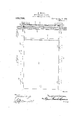
- Figure 1 is a conventional view of the front of a piano showing one of which embodies the present invention and is movable longitudinally in the direction indicated by the arrow.
- Fig. 2 is a top plan view of the track upon which one embodiment of the present invention slides.
- Fig. 3 is a top plan view of the track shown with the panel player moved to open position.
- Fig. 4 is a top plan view of the track showing a single track instead of a double track as shown in Figs. 2 and 3 and with the panel in closed position.
- Fig. 5 is a top plan View of the singie track construction, such as shown at Fig. 4, shown with the panel in open position.
- Fig. 6 is a front elevation of the movable which engage the track grooves.
- Fig. 7 is a transverse sectional view of the track HALLET 3r DAVIS PIANO 00., OF
- Fig. 8 is a transverse sectional view of the frame and single track showing the sliding panel in end elevation.
- the frame 10 of the present construction is similar in most respects to the ordinary front frame portions of the ordinary piano and embodies the usual upright portions and horizontal portions dividing the front into panels 11 upon the ends and 12 in the cen ter, the latter of which is the movable panel.
- the sliding 'ianel 12 is provided with pintles l3 and 13' adapted to engage and slide within grooves 14 and 15, respectively, formed in the guide strips 16- which may be integral -with the frame construction of the piano or may be separate strips as shown at Figs. 7 and 8.
- the grooves 14 and 15 curve suddenly backward so that the first movement of the sliding panel when actuated by engagement with the knob or handie 17 is rearwardly and the panel itself is preferably provided at its forward edge with a bevel 18 more readily to pass over the beveled corner 19 of the frame-work 10.
- About the opening is, of course, employed the usual head or molding 20, the same in relation to all of the panels, which bead or molding forms an. abutment against which the sliding tion.
- a spring 21 is employed hearing upon the inner surface of the movable panel at what is normally the forward edge in the opening movement, so that as the sliding panel moves to closed position the pressure of the spring 21 upon such sliding panel will force the pintle 13 to enter the groove 15 to close the slidingpanel to the position shown in Fig. i.
- What I claim is 1.
Landscapes
- Engineering & Computer Science (AREA)
- Civil Engineering (AREA)
- Structural Engineering (AREA)
- Physics & Mathematics (AREA)
- Acoustics & Sound (AREA)
- Multimedia (AREA)
- Securing Of Glass Panes Or The Like (AREA)
Description
R. GLOSSA. DOOR FOR PIANO PLAYERS. APPLICATION FILED 001229. 1908.
93 1 ,752; Patented Aug. 24. 1909.
3 SHEETS-SHEET 1.
witne/auo j M auwmu a R. GLOSSA.
DOOR FOR PIANO PLAYERS.
APPLICATION FILED 00129, 1908.
Patented Aug. 24,1909.
3 SHEBTS- HBBT 2.
R. GLO sA.
DOOR FOR PIANO PLAYERS.
APPLICATION FILED OCT. 29, 1 03.
3 SHEETS-SHEET 3.
N IE s w I 71 I I I @I I III I I I I [I I I I I I II :18 II I I :I I I I Q I I I I I I Q I I I k I I I I I I I I 8 I I I I I I I I I I II I I I I I I. I -I' I I I I I L I I I I Q I I I I I Q) l I I I I gnoenfoz j I 1, I
attoznu a the main three panels, the center ma n-n RAYMOND GLOSSA, 0F BOSTON, MASSACHUSETTS, ASSlGNOR TO BOSTON, MASSACHUSETTS, A COE3?0RATION OF MAINE.
DOOR FOR PIANO-PLAYERS.
Specification of Letters Patent.
Application filed October 29, 1908. Serial No. 460/1291 To all whom it may concern:
Be it known that I, Raynor!) GLOSSA, a
citizen of the United States, residing at Boston, in the county of Suffolk and State of Massachusetts, have'invented certain new and useful Improvements in Doors for Piano-Players; and I do hereby declare the following to be a full, clear, and exact description of the invention, such as will enable others skilled in the art to which it appertains to make and use the same.
This invention relates to doors for pianos, and has for an object to provide a door resembling in all respects one of the regular panels of the piano front. It is well known that in player pianos where a tracker bar is positioned above the keyboard, a panel is ordinarily employed movable in some way vertically slidable, which opens the recess within the body of the piano in which the tracker bar andassociate mechanism is disposed.
In the ordinary iano construction the panels in the front of the piano are set about a quarter of an inch deep with respect to portion of the front of the piano and in the ordinary construction of the player piano sliding panel it is necessary to have such panel set deep enough to clear the construction of the front of the piano ordinarily an inch thick so that the panels upon the side do not'correspond in depth with the center or movable piano.
Another obje'ctbf the present invention is to provide a center movable piano which in closed position will appear to the eye practically the same as the side panels and be disposed at substantially the same depth but with provision for moving the panel to clear the frame construction as well asthe side panel toward which it moves.
With these and other objects in view, the invention comprises certain novel constructions, arrangements and combinations of parts, as .will be hereinafter fully described and claimed.
In the drawings :Figure 1 is a conventional view of the front of a piano showing one of which embodies the present invention and is movable longitudinally in the direction indicated by the arrow. Fig. 2 is a top plan view of the track upon which one embodiment of the present invention slides. Fig. 3 is a top plan view of the track shown with the panel player moved to open position. Fig. 4 is a top plan view of the track showing a single track instead of a double track as shown in Figs. 2 and 3 and with the panel in closed position. Fig. 5 is a top plan View of the singie track construction, such as shown at Fig. 4, shown with the panel in open position. Fig. 6 is a front elevation of the movable which engage the track grooves. Fig. 7 is a transverse sectional view of the track HALLET 3r DAVIS PIANO 00., OF
Patented Aug. '24., 1909.
panel removed showing the pintles showing the panels in end elevation, and of the double track embodiment. Fig. 8 is a transverse sectional view of the frame and single track showing the sliding panel in end elevation.
Like characters of references designate corresponding parts throughout the several views.
The frame 10 of the present construction is similar in most respects to the ordinary front frame portions of the ordinary piano and embodies the usual upright portions and horizontal portions dividing the front into panels 11 upon the ends and 12 in the cen ter, the latter of which is the movable panel.
1 It will be noted, especially from F igs. 2 to r inclusive, that the frame construction of the piano shown at 10 is such that the pancls, both 11 and 12, are seated wholly within the thickness of such frame construction and cannot be moved horizontally without. in
some manner clearing the frame construction. To accomplish this purpose the sliding 'ianel 12 is provided with pintles l3 and 13' adapted to engage and slide within grooves 14 and 15, respectively, formed in the guide strips 16- which may be integral -with the frame construction of the piano or may be separate strips as shown at Figs. 7 and 8.
It will be noted that the grooves 14 and 15 curve suddenly backward so that the first movement of the sliding panel when actuated by engagement with the knob or handie 17 is rearwardly and the panel itself is preferably provided at its forward edge with a bevel 18 more readily to pass over the beveled corner 19 of the frame-work 10. About the opening is, of course, employed the usual head or molding 20, the same in relation to all of the panels, which bead or molding forms an. abutment against which the sliding tion.
panel rests when' in closed posi- It will be noted from Figs. 2 and 3 that the groove 14 is disposed farther rearwardly than the groove 15 so that the sliding panel 12, when in open position, is disposed somethe oifset groove 15 as shown in dotted lines in,Fig..(' and the pintles 13 are longer than the pintles 13 so that the 'pintles 13 may not enter within the groove 15' bntwill always follow the groove lat. By this arrangement it will be seen that the first movement of the sliding panel ofthe con struction shown at Figs. at and 5 is similar to that shown at Figs. 3 and 4, to wit, suddenly 'rearwardly, the pintle 13 following thegroove 15 and the pintle 13 following the groove 14 until the pintle 13 passes from the groove 15 into the groove 1-1; when both pintles follow the same groove as shown particularly in Fig. 5 with the sliding panel parallel with the stationary panel 11.
In closing the reverse movement is followed, and to insure the pintle 13 entering the groove 15- a spring 21 is employed hearing upon the inner surface of the movable panel at what is normally the forward edge in the opening movement, so that as the sliding panel moves to closed position the pressure of the spring 21 upon such sliding panel will force the pintle 13 to enter the groove 15 to close the slidingpanel to the position shown in Fig. i.
It is customary to employ a plate of glass within the sliding panel to close over the tracker bar while the player piano is heing operated, and for such purpose a groove 22 is employed in which a sheet of glass 23 is mounted to move slidabiy.
'hilethe member l6 containing the grooves are shown in plan as the bottom only, it is to be understood, of course, that similar reverse grooves are employed above the upper edge of the sliding panel to accommodate the upper pintles l3 and 13 in similar manner.
What I claim is 1. The combination with a frame, of guide strips defining a panel opening and provided'with grooves of different depths, and a pane provided with pintles of different lengths adapted to move selectively in the grooves of different depths.
2. The combination with a frame defining a door opening and having inclined grooves of different depths extending from adjacent each side of the opening and leading to and communicating with a longitudinal groove, of a panel adapted to close the ope ingand having pintles of different lengths at each side seated and movable each within one of the grooves.
3. The combination with a frame defining a door opening having inclined grooves of different depths. extending from adjacent each side of the opening and leading to and both communicating with a single longitudinal groove, of a panel adapted to close the opening and having pin-.ies of difierent lengths at each side seated and movable each within one of the grooves of different depths and both within the longitudinal grooves.
In testimony whereof I affix my signature in presence of two witnesses.
RAYMOND GLossA.
ilVitnesses E. E. CONWAY, H. J. SHAFER.
Priority Applications (1)
| Application Number | Priority Date | Filing Date | Title |
|---|---|---|---|
| US46012908A US931752A (en) | 1908-10-29 | 1908-10-29 | Door for piano-players. |
Applications Claiming Priority (1)
| Application Number | Priority Date | Filing Date | Title |
|---|---|---|---|
| US46012908A US931752A (en) | 1908-10-29 | 1908-10-29 | Door for piano-players. |
Publications (1)
| Publication Number | Publication Date |
|---|---|
| US931752A true US931752A (en) | 1909-08-24 |
Family
ID=3000176
Family Applications (1)
| Application Number | Title | Priority Date | Filing Date |
|---|---|---|---|
| US46012908A Expired - Lifetime US931752A (en) | 1908-10-29 | 1908-10-29 | Door for piano-players. |
Country Status (1)
| Country | Link |
|---|---|
| US (1) | US931752A (en) |
-
1908
- 1908-10-29 US US46012908A patent/US931752A/en not_active Expired - Lifetime
Similar Documents
| Publication | Publication Date | Title |
|---|---|---|
| US3280506A (en) | Flush closing sliding door assembly | |
| US263670A (en) | b auoh | |
| US908199A (en) | Car-end construction. | |
| US2644205A (en) | Sliding door structure | |
| US650036A (en) | Hinge for double-acting doors. | |
| US1061008A (en) | Door for show-cases and other inclosures. | |
| US641844A (en) | Door. | |
| US853859A (en) | Elevator-door mechanism. | |
| US456136A (en) | bullingker | |
| US646129A (en) | Bookcase, &c. | |
| US911454A (en) | Sliding and swinging sash. | |
| US671642A (en) | Window. | |
| US1509707A (en) | Sliding sash window | |
| US1094695A (en) | Show-case door. | |
| US370502A (en) | Freight-car door | |
| US1354562A (en) | Sliding door | |
| US1063954A (en) | Key-slip. | |
| US1141390A (en) | Weather-strip attachment. | |
| US1073638A (en) | Window. | |
| US380747A (en) | Window-screen | |
| US803026A (en) | Weather-strip. | |
| US696029A (en) | Hinge for doors. | |
| US1049223A (en) | Hollow-metal window construction. | |
| US1575435A (en) | Window lock | |
| US572521A (en) | bbadshaw |