US9317050B2 - Method and apparatus for controlling converter in full cell vehicle - Google Patents
Method and apparatus for controlling converter in full cell vehicle Download PDFInfo
- Publication number
- US9317050B2 US9317050B2 US14/095,602 US201314095602A US9317050B2 US 9317050 B2 US9317050 B2 US 9317050B2 US 201314095602 A US201314095602 A US 201314095602A US 9317050 B2 US9317050 B2 US 9317050B2
- Authority
- US
- United States
- Prior art keywords
- reference signal
- converter
- signal
- current
- triangular wave
- Prior art date
- Legal status (The legal status is an assumption and is not a legal conclusion. Google has not performed a legal analysis and makes no representation as to the accuracy of the status listed.)
- Active, expires
Links
- 238000000034 method Methods 0.000 title claims abstract description 22
- 230000008859 change Effects 0.000 claims abstract description 44
- 239000000446 fuel Substances 0.000 claims abstract description 44
- 238000010586 diagram Methods 0.000 description 11
- 238000006243 chemical reaction Methods 0.000 description 3
- 230000006870 function Effects 0.000 description 3
- 239000007800 oxidant agent Substances 0.000 description 3
- 230000001590 oxidative effect Effects 0.000 description 3
- UFHFLCQGNIYNRP-UHFFFAOYSA-N Hydrogen Chemical compound [H][H] UFHFLCQGNIYNRP-UHFFFAOYSA-N 0.000 description 2
- 230000005611 electricity Effects 0.000 description 2
- 229910052739 hydrogen Inorganic materials 0.000 description 2
- 239000001257 hydrogen Substances 0.000 description 2
- 238000007254 oxidation reaction Methods 0.000 description 2
- 230000008569 process Effects 0.000 description 2
- 238000006722 reduction reaction Methods 0.000 description 2
- 239000000126 substance Substances 0.000 description 2
- XLYOFNOQVPJJNP-UHFFFAOYSA-N water Substances O XLYOFNOQVPJJNP-UHFFFAOYSA-N 0.000 description 2
- 230000008901 benefit Effects 0.000 description 1
- 239000003990 capacitor Substances 0.000 description 1
- 239000007795 chemical reaction product Substances 0.000 description 1
- 239000002826 coolant Substances 0.000 description 1
- 238000013500 data storage Methods 0.000 description 1
- 230000003247 decreasing effect Effects 0.000 description 1
- 238000007599 discharging Methods 0.000 description 1
- 238000003487 electrochemical reaction Methods 0.000 description 1
- 230000007717 exclusion Effects 0.000 description 1
- 230000006872 improvement Effects 0.000 description 1
- 230000004048 modification Effects 0.000 description 1
- 238000012986 modification Methods 0.000 description 1
- 230000003287 optical effect Effects 0.000 description 1
- 230000002093 peripheral effect Effects 0.000 description 1
- 239000003208 petroleum Substances 0.000 description 1
- 239000000376 reactant Substances 0.000 description 1
- 230000036647 reaction Effects 0.000 description 1
- 230000009467 reduction Effects 0.000 description 1
- 230000001172 regenerating effect Effects 0.000 description 1
Images


Classifications
-
- G—PHYSICS
- G05—CONTROLLING; REGULATING
- G05F—SYSTEMS FOR REGULATING ELECTRIC OR MAGNETIC VARIABLES
- G05F1/00—Automatic systems in which deviations of an electric quantity from one or more predetermined values are detected at the output of the system and fed back to a device within the system to restore the detected quantity to its predetermined value or values, i.e. retroactive systems
- G05F1/10—Regulating voltage or current
- G05F1/46—Regulating voltage or current wherein the variable actually regulated by the final control device is DC
- G05F1/462—Regulating voltage or current wherein the variable actually regulated by the final control device is DC as a function of the requirements of the load, e.g. delay, temperature, specific voltage/current characteristic
-
- B60L11/00—
-
- B—PERFORMING OPERATIONS; TRANSPORTING
- B60—VEHICLES IN GENERAL
- B60L—PROPULSION OF ELECTRICALLY-PROPELLED VEHICLES; SUPPLYING ELECTRIC POWER FOR AUXILIARY EQUIPMENT OF ELECTRICALLY-PROPELLED VEHICLES; ELECTRODYNAMIC BRAKE SYSTEMS FOR VEHICLES IN GENERAL; MAGNETIC SUSPENSION OR LEVITATION FOR VEHICLES; MONITORING OPERATING VARIABLES OF ELECTRICALLY-PROPELLED VEHICLES; ELECTRIC SAFETY DEVICES FOR ELECTRICALLY-PROPELLED VEHICLES
- B60L58/00—Methods or circuit arrangements for monitoring or controlling batteries or fuel cells, specially adapted for electric vehicles
- B60L58/40—Methods or circuit arrangements for monitoring or controlling batteries or fuel cells, specially adapted for electric vehicles for controlling a combination of batteries and fuel cells
-
- H—ELECTRICITY
- H01—ELECTRIC ELEMENTS
- H01M—PROCESSES OR MEANS, e.g. BATTERIES, FOR THE DIRECT CONVERSION OF CHEMICAL ENERGY INTO ELECTRICAL ENERGY
- H01M8/00—Fuel cells; Manufacture thereof
- H01M8/04—Auxiliary arrangements, e.g. for control of pressure or for circulation of fluids
- H01M8/04298—Processes for controlling fuel cells or fuel cell systems
- H01M8/04313—Processes for controlling fuel cells or fuel cell systems characterised by the detection or assessment of variables; characterised by the detection or assessment of failure or abnormal function
- H01M8/04537—Electric variables
- H01M8/04544—Voltage
- H01M8/04567—Voltage of auxiliary devices, e.g. batteries, capacitors
-
- H—ELECTRICITY
- H01—ELECTRIC ELEMENTS
- H01M—PROCESSES OR MEANS, e.g. BATTERIES, FOR THE DIRECT CONVERSION OF CHEMICAL ENERGY INTO ELECTRICAL ENERGY
- H01M8/00—Fuel cells; Manufacture thereof
- H01M8/04—Auxiliary arrangements, e.g. for control of pressure or for circulation of fluids
- H01M8/04298—Processes for controlling fuel cells or fuel cell systems
- H01M8/04694—Processes for controlling fuel cells or fuel cell systems characterised by variables to be controlled
- H01M8/04858—Electric variables
- H01M8/04895—Current
- H01M8/04917—Current of auxiliary devices, e.g. batteries, capacitors
-
- H—ELECTRICITY
- H02—GENERATION; CONVERSION OR DISTRIBUTION OF ELECTRIC POWER
- H02M—APPARATUS FOR CONVERSION BETWEEN AC AND AC, BETWEEN AC AND DC, OR BETWEEN DC AND DC, AND FOR USE WITH MAINS OR SIMILAR POWER SUPPLY SYSTEMS; CONVERSION OF DC OR AC INPUT POWER INTO SURGE OUTPUT POWER; CONTROL OR REGULATION THEREOF
- H02M1/00—Details of apparatus for conversion
-
- H—ELECTRICITY
- H02—GENERATION; CONVERSION OR DISTRIBUTION OF ELECTRIC POWER
- H02M—APPARATUS FOR CONVERSION BETWEEN AC AND AC, BETWEEN AC AND DC, OR BETWEEN DC AND DC, AND FOR USE WITH MAINS OR SIMILAR POWER SUPPLY SYSTEMS; CONVERSION OF DC OR AC INPUT POWER INTO SURGE OUTPUT POWER; CONTROL OR REGULATION THEREOF
- H02M3/00—Conversion of DC power input into DC power output
- H02M3/02—Conversion of DC power input into DC power output without intermediate conversion into AC
- H02M3/04—Conversion of DC power input into DC power output without intermediate conversion into AC by static converters
- H02M3/10—Conversion of DC power input into DC power output without intermediate conversion into AC by static converters using discharge tubes with control electrode or semiconductor devices with control electrode
- H02M3/145—Conversion of DC power input into DC power output without intermediate conversion into AC by static converters using discharge tubes with control electrode or semiconductor devices with control electrode using devices of a triode or transistor type requiring continuous application of a control signal
- H02M3/155—Conversion of DC power input into DC power output without intermediate conversion into AC by static converters using discharge tubes with control electrode or semiconductor devices with control electrode using devices of a triode or transistor type requiring continuous application of a control signal using semiconductor devices only
- H02M3/156—Conversion of DC power input into DC power output without intermediate conversion into AC by static converters using discharge tubes with control electrode or semiconductor devices with control electrode using devices of a triode or transistor type requiring continuous application of a control signal using semiconductor devices only with automatic control of output voltage or current, e.g. switching regulators
-
- B—PERFORMING OPERATIONS; TRANSPORTING
- B60—VEHICLES IN GENERAL
- B60L—PROPULSION OF ELECTRICALLY-PROPELLED VEHICLES; SUPPLYING ELECTRIC POWER FOR AUXILIARY EQUIPMENT OF ELECTRICALLY-PROPELLED VEHICLES; ELECTRODYNAMIC BRAKE SYSTEMS FOR VEHICLES IN GENERAL; MAGNETIC SUSPENSION OR LEVITATION FOR VEHICLES; MONITORING OPERATING VARIABLES OF ELECTRICALLY-PROPELLED VEHICLES; ELECTRIC SAFETY DEVICES FOR ELECTRICALLY-PROPELLED VEHICLES
- B60L1/00—Supplying electric power to auxiliary equipment of vehicles
- B60L1/02—Supplying electric power to auxiliary equipment of vehicles to electric heating circuits
- B60L1/04—Supplying electric power to auxiliary equipment of vehicles to electric heating circuits fed by the power supply line
- B60L1/10—Supplying electric power to auxiliary equipment of vehicles to electric heating circuits fed by the power supply line with provision for using different supplies
- B60L1/12—Methods and devices for control or regulation
-
- B—PERFORMING OPERATIONS; TRANSPORTING
- B60—VEHICLES IN GENERAL
- B60L—PROPULSION OF ELECTRICALLY-PROPELLED VEHICLES; SUPPLYING ELECTRIC POWER FOR AUXILIARY EQUIPMENT OF ELECTRICALLY-PROPELLED VEHICLES; ELECTRODYNAMIC BRAKE SYSTEMS FOR VEHICLES IN GENERAL; MAGNETIC SUSPENSION OR LEVITATION FOR VEHICLES; MONITORING OPERATING VARIABLES OF ELECTRICALLY-PROPELLED VEHICLES; ELECTRIC SAFETY DEVICES FOR ELECTRICALLY-PROPELLED VEHICLES
- B60L2210/00—Converter types
- B60L2210/10—DC to DC converters
-
- H—ELECTRICITY
- H01—ELECTRIC ELEMENTS
- H01M—PROCESSES OR MEANS, e.g. BATTERIES, FOR THE DIRECT CONVERSION OF CHEMICAL ENERGY INTO ELECTRICAL ENERGY
- H01M2250/00—Fuel cells for particular applications; Specific features of fuel cell system
- H01M2250/20—Fuel cells in motive systems, e.g. vehicle, ship, plane
-
- H—ELECTRICITY
- H02—GENERATION; CONVERSION OR DISTRIBUTION OF ELECTRIC POWER
- H02M—APPARATUS FOR CONVERSION BETWEEN AC AND AC, BETWEEN AC AND DC, OR BETWEEN DC AND DC, AND FOR USE WITH MAINS OR SIMILAR POWER SUPPLY SYSTEMS; CONVERSION OF DC OR AC INPUT POWER INTO SURGE OUTPUT POWER; CONTROL OR REGULATION THEREOF
- H02M1/00—Details of apparatus for conversion
- H02M1/0003—Details of control, feedback or regulation circuits
- H02M1/0009—Devices or circuits for detecting current in a converter
-
- H—ELECTRICITY
- H02—GENERATION; CONVERSION OR DISTRIBUTION OF ELECTRIC POWER
- H02M—APPARATUS FOR CONVERSION BETWEEN AC AND AC, BETWEEN AC AND DC, OR BETWEEN DC AND DC, AND FOR USE WITH MAINS OR SIMILAR POWER SUPPLY SYSTEMS; CONVERSION OF DC OR AC INPUT POWER INTO SURGE OUTPUT POWER; CONTROL OR REGULATION THEREOF
- H02M1/00—Details of apparatus for conversion
- H02M1/0003—Details of control, feedback or regulation circuits
- H02M1/0025—Arrangements for modifying reference values, feedback values or error values in the control loop of a converter
-
- H—ELECTRICITY
- H02—GENERATION; CONVERSION OR DISTRIBUTION OF ELECTRIC POWER
- H02M—APPARATUS FOR CONVERSION BETWEEN AC AND AC, BETWEEN AC AND DC, OR BETWEEN DC AND DC, AND FOR USE WITH MAINS OR SIMILAR POWER SUPPLY SYSTEMS; CONVERSION OF DC OR AC INPUT POWER INTO SURGE OUTPUT POWER; CONTROL OR REGULATION THEREOF
- H02M1/00—Details of apparatus for conversion
- H02M1/32—Means for protecting converters other than automatic disconnection
-
- H02M2001/0009—
-
- H02M2001/0025—
-
- H—ELECTRICITY
- H02—GENERATION; CONVERSION OR DISTRIBUTION OF ELECTRIC POWER
- H02M—APPARATUS FOR CONVERSION BETWEEN AC AND AC, BETWEEN AC AND DC, OR BETWEEN DC AND DC, AND FOR USE WITH MAINS OR SIMILAR POWER SUPPLY SYSTEMS; CONVERSION OF DC OR AC INPUT POWER INTO SURGE OUTPUT POWER; CONTROL OR REGULATION THEREOF
- H02M3/00—Conversion of DC power input into DC power output
- H02M3/22—Conversion of DC power input into DC power output with intermediate conversion into AC
- H02M3/24—Conversion of DC power input into DC power output with intermediate conversion into AC by static converters
- H02M3/28—Conversion of DC power input into DC power output with intermediate conversion into AC by static converters using discharge tubes with control electrode or semiconductor devices with control electrode to produce the intermediate AC
- H02M3/325—Conversion of DC power input into DC power output with intermediate conversion into AC by static converters using discharge tubes with control electrode or semiconductor devices with control electrode to produce the intermediate AC using devices of a triode or a transistor type requiring continuous application of a control signal
- H02M3/335—Conversion of DC power input into DC power output with intermediate conversion into AC by static converters using discharge tubes with control electrode or semiconductor devices with control electrode to produce the intermediate AC using devices of a triode or a transistor type requiring continuous application of a control signal using semiconductor devices only
- H02M3/33507—Conversion of DC power input into DC power output with intermediate conversion into AC by static converters using discharge tubes with control electrode or semiconductor devices with control electrode to produce the intermediate AC using devices of a triode or a transistor type requiring continuous application of a control signal using semiconductor devices only with automatic control of the output voltage or current, e.g. flyback converters
-
- Y—GENERAL TAGGING OF NEW TECHNOLOGICAL DEVELOPMENTS; GENERAL TAGGING OF CROSS-SECTIONAL TECHNOLOGIES SPANNING OVER SEVERAL SECTIONS OF THE IPC; TECHNICAL SUBJECTS COVERED BY FORMER USPC CROSS-REFERENCE ART COLLECTIONS [XRACs] AND DIGESTS
- Y02—TECHNOLOGIES OR APPLICATIONS FOR MITIGATION OR ADAPTATION AGAINST CLIMATE CHANGE
- Y02E—REDUCTION OF GREENHOUSE GAS [GHG] EMISSIONS, RELATED TO ENERGY GENERATION, TRANSMISSION OR DISTRIBUTION
- Y02E60/00—Enabling technologies; Technologies with a potential or indirect contribution to GHG emissions mitigation
- Y02E60/30—Hydrogen technology
- Y02E60/50—Fuel cells
-
- Y—GENERAL TAGGING OF NEW TECHNOLOGICAL DEVELOPMENTS; GENERAL TAGGING OF CROSS-SECTIONAL TECHNOLOGIES SPANNING OVER SEVERAL SECTIONS OF THE IPC; TECHNICAL SUBJECTS COVERED BY FORMER USPC CROSS-REFERENCE ART COLLECTIONS [XRACs] AND DIGESTS
- Y02—TECHNOLOGIES OR APPLICATIONS FOR MITIGATION OR ADAPTATION AGAINST CLIMATE CHANGE
- Y02T—CLIMATE CHANGE MITIGATION TECHNOLOGIES RELATED TO TRANSPORTATION
- Y02T10/00—Road transport of goods or passengers
- Y02T10/60—Other road transportation technologies with climate change mitigation effect
- Y02T10/70—Energy storage systems for electromobility, e.g. batteries
-
- Y—GENERAL TAGGING OF NEW TECHNOLOGICAL DEVELOPMENTS; GENERAL TAGGING OF CROSS-SECTIONAL TECHNOLOGIES SPANNING OVER SEVERAL SECTIONS OF THE IPC; TECHNICAL SUBJECTS COVERED BY FORMER USPC CROSS-REFERENCE ART COLLECTIONS [XRACs] AND DIGESTS
- Y02—TECHNOLOGIES OR APPLICATIONS FOR MITIGATION OR ADAPTATION AGAINST CLIMATE CHANGE
- Y02T—CLIMATE CHANGE MITIGATION TECHNOLOGIES RELATED TO TRANSPORTATION
- Y02T10/00—Road transport of goods or passengers
- Y02T10/60—Other road transportation technologies with climate change mitigation effect
- Y02T10/72—Electric energy management in electromobility
-
- Y—GENERAL TAGGING OF NEW TECHNOLOGICAL DEVELOPMENTS; GENERAL TAGGING OF CROSS-SECTIONAL TECHNOLOGIES SPANNING OVER SEVERAL SECTIONS OF THE IPC; TECHNICAL SUBJECTS COVERED BY FORMER USPC CROSS-REFERENCE ART COLLECTIONS [XRACs] AND DIGESTS
- Y02—TECHNOLOGIES OR APPLICATIONS FOR MITIGATION OR ADAPTATION AGAINST CLIMATE CHANGE
- Y02T—CLIMATE CHANGE MITIGATION TECHNOLOGIES RELATED TO TRANSPORTATION
- Y02T90/00—Enabling technologies or technologies with a potential or indirect contribution to GHG emissions mitigation
- Y02T90/40—Application of hydrogen technology to transportation, e.g. using fuel cells
Definitions
- the present invention relates to control of a converter, and more particularly, to an apparatus and a method of controlling a large capacity converter used in a fuel cell vehicle.
- Fuel cells convert chemical energy generated by oxidization of fuel into electrical energy.
- fuel cells and batteries both utilize a chemical cell which performs an oxidization and reduction reaction, in a battery, the cell reaction is generated inside a closed system, whereas in a fuel cell the fuel and oxidant (reactants) are continuously supplied from outside of the system and then are continuously removed to outside of the system again once the reaction has occurred.
- fuel cells have begun to be commercialized, and since a reaction product of the fuel cell is pure water, research related to the use of water as an energy source of an environmentally-friendly vehicle has been actively pursued.
- a fuel cell vehicle utilizes a hybrid system that has a secondary energy storing device, such as a battery or a super capacitor, in addition to the fuel cell, which is the primary energy source.
- a bi-directional converter serves to maintain a uniform fuel utilization rate and balance power between the fuel cell and a load by charging and discharging the appropriate amount of energy through an energy storing device, such as a battery.
- a large capacity bi-directional converter is typically used to control the voltage of a direct current terminal, but when an inverter connected to a motor is regeneratively braked, the bi-directional converter operates in a hybrid control mode, in which output current and power are controlled together or simultaneously, in order to prevent overcurrent failure to from being generated due to a rapid change in the current.
- PWM pulse width modulation
- This chip is a PWM generation chip that is appropriate for a small or medium power converter.
- the maximum value of a triangular wave for generating the PWM is determined by the size of the chip, and thus the size of the maximum value is limited as a result. Accordingly, there is a limit to the amount of control offer for a large capacity converter, such as a fuel cell system.
- FIG. 1 is a graph illustrating a triangular wave generated in a dedicated chip for controlling PWM in the related art. As illustrated in FIG. 1 , when the dedicated chip is used, a maximum value of the triangular wave is fixed at approximately 2.3 V. Since maximum value of the triangular wave is limited and thus the amount of control offered, resolution and the degree of level precision of the overall control deteriorate as well. Additionally, the dynamic nature of the system is degraded.
- the present invention has been made in an effort to provide an apparatus and a method capable of effectively controlling a large capacity converter though pulse width modulation (PWM) control, in which a range of a triangular wave is expanded, in a fuel cell vehicle.
- PWM pulse width modulation
- An exemplary embodiment of the present invention provides an apparatus for controlling a converter of a fuel cell vehicle, including: a current reference signal change rate amplifier configured to use a power control value for power control of the converter as a reference value, and generate a current reference signal based on the reference value; a current sensor (e.g., sensor) configured to detect output terminal current of the converter; a current controller configured to compare the current reference signal and the detected output terminal current to output a final reference signal; a triangular wave generator configured to generate triangular wave; a triangular wave amplifier configured to amplify the generated triangular wave signal; and a comparison unit configured to compare the amplified triangular wave signal and the final reference signal to output a pulse wave signal that controls the converter.
- a current reference signal change rate amplifier configured to use a power control value for power control of the converter as a reference value, and generate a current reference signal based on the reference value
- a current sensor e.g., sensor
- a current controller configured to compare the current reference signal and
- the apparatus may further include a hybrid controller configured to detect an inverter DC terminal voltage input into an inverter connected to a motor of the vehicle, generate the power control value based on the inverter DC terminal voltage, and output the generated power control value to the current reference signal change rate amplifier.
- a hybrid controller configured to detect an inverter DC terminal voltage input into an inverter connected to a motor of the vehicle, generate the power control value based on the inverter DC terminal voltage, and output the generated power control value to the current reference signal change rate amplifier.
- the current reference signal change rate amplifier may set a change rate corresponding to the reference value based on changes rates having different predetermined values for each reference value, and output the current reference signal amplified according to the set change rate.
- the comparison unit may be configured to output a pulse wave signal of which a change range of a duty ratio is increased by the final reference signal generated based on the amplified triangular wave signal and the current reference signal amplified according to the change rate.
- the converter may be a bi-directional high voltage DC-DC converter (BHDC).
- BHDC bi-directional high voltage DC-DC converter
- Another exemplary embodiment of the present invention provides a method of controlling a converter of a fuel cell vehicle, including: detecting, by a sensor, an inverter DC terminal voltage input in an inverter connected to a motor of the vehicle, and generating, by a controller, a power control value that controls the converter based on the inverter DC terminal voltage; using the power control value that controls power of the converter as a reference value, generating, by a first amplifier, a current reference signal based on the reference value, and outputting the generated current reference signal; outputting, by the first amplifier a final reference signal for generating a pulse width modulation (PWM) signal by compensating for the current reference signal based on output terminal current of the converter; generating a triangular wave signal by a wave generator, and amplifying, by a second amplifier, the triangular wave signal; and comparing, by a comparison unit, the amplified triangular wave signal and the final reference signal, generating, by the comparison unit, the PWM signal having a predetermined duty ratio,
- generating of the current reference signal and the outputting of the generated current reference signal may include setting a change rate corresponding to the reference value based on changes rates having different predetermined values for each reference value, and outputting the current reference signal amplified according to the set change
- FIG. 1 is a graph illustrating a triangular wave generated in a dedicated chip for PWM control in the related art.
- FIG. 2 is a diagram illustrating a structure of a fuel cell vehicle according to an exemplary embodiment of the present invention
- FIG. 3 is a diagram illustrating a structure of a converter control apparatus according to the exemplary embodiment of the present invention.
- FIG. 4 is a flowchart of a method of controlling the converter according to the exemplary embodiment of the present invention.
- FIGS. 5A and 5B are diagrams illustrating characteristics of a triangular wave signal and a PWM signal generated by the converter control apparatus according to the exemplary embodiment of the present invention, and characteristics of a triangular wave signal and a PWM signal generated by the commercialized PWM chip in the related art, respectively.
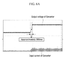
- FIG. 6A is a diagram illustrating a vehicle start waveform obtained in a case where a vehicle start is performed according to the converter control device according to the exemplary embodiment of the present invention
- FIG. 6B is a diagram illustrating a vehicle start waveform obtained in a case where a vehicle start is performed based on the commercialized PWM chip in the related art.
- vehicle or “vehicular” or other similar term as used herein is inclusive of motor vehicles in general such as passenger automobiles including sports utility vehicles (SUV), buses, trucks, various commercial vehicles, watercraft including a variety of boats and ships, aircraft, and the like, and includes hybrid vehicles, electric vehicles, plug-in hybrid electric vehicles, hydrogen-powered vehicles, fuel cell vehicles and other alternative fuel vehicles (e.g. fuels derived from resources other than petroleum).
- a hybrid vehicle is a vehicle that has two or more sources of power, for example both gasoline-powered and electric-powered vehicles.
- controller refers to a hardware device that includes a memory and a processor.
- the memory is configured to store the modules/units and the processor is specifically configured to execute said units to perform one or more processes algorithmically. These processes are described further below. Additionally, each of these units may be controlled by the same processor or different processors without diverting from the overall intention of the is present invention. Therefore, the processor by which the each unit is executed is irrelevant to overall operation of the present invention.
- control logic of the present invention may be embodied as non-transitory computer readable media on a computer readable medium containing executable program instructions executed by a processor, controller or the like.
- the computer readable mediums include, but are not limited to, ROM, RAM, compact disc (CD)-ROMs, magnetic tapes, floppy disks, flash drives, smart cards and optical data storage devices.
- the computer readable recording medium can also be distributed in network coupled computer systems so that the computer readable media is stored and executed in a distributed fashion, e.g., by a telematics server or a Controller Area Network (CAN).
- a telematics server or a Controller Area Network (CAN).
- CAN Controller Area Network
- FIG. 2 is a diagram illustrating a structure of a fuel cell vehicle according to an exemplary embodiment of the present invention.
- the fuel cell vehicle according to the exemplary embodiment of the present invention includes a fuel cell 10 operating as a main power source of the fuel cell vehicle, a battery 20 operating as an auxiliary power source for the fuel cell vehicle, a bi-directional high voltage DC-DC converter (BHDC) 30 , an auxiliary battery 40 , a lower voltage DC-DC converter (LDC) 50 , an inverter 60 , a motor 70 , and a junction box 80 .
- BHDC high voltage DC-DC converter
- LDC lower voltage DC-DC converter
- the fuel cell 10 receives fuel (e.g., hydrogen) from a storage tank and receives an oxidant (e.g., air) from a supply device (not illustrated) to generate electricity via an electrochemical reaction of the fuel and oxidant.
- fuel e.g., hydrogen
- oxidant e.g., air
- the battery 20 charges the electricity generated by the fuel cell 10 , and supplies power for driving several fuel cell balance of plants (BOP) (including the air blower, a hydrogen recirculation blower, a coolant circulating pump, and the like) necessary for the driving of the fuel cell.
- BOP fuel cell balance of plants
- the BHDC 30 may be a bi-directional converter that matches a balance between different output voltages of the high voltage battery 20 and the fuel cell 10 . That is, the BHDC 30 boosts the voltage from a high voltage battery to output the boosted voltage to a high voltage bus terminal, starts the fuel cell 10 , and charges the high voltage battery 20 by decreasing the high voltage to a predetermined voltage.
- the auxiliary battery 40 may be a 12 V battery that supplies power to components of the vehicle using a predetermined driving voltage.
- the components using the auxiliary battery 10 as the power source continuously consume power during the driving of the vehicle, as such, the LDC 50 controls the power supply of the auxiliary battery 10 in order to charge the components.
- the inverter 60 and the motor 70 may be connected to the high voltage bus terminal to which the fuel cell 10 and the BHDC 30 are connected.
- the inverter 60 is configured to switch a voltage input from the high voltage bus terminal, convert the switched voltage to a three-phase AC power source, and then supply the converted three-phase AC power source to the motor 70 as a means of driving the motor.
- the junction box 80 in the illustrative embodiment of the present invention is disposed between the BHDC 30 and the inverter 60 , to control the amount of power transmitted to the battery 20 and to control the amount of power transmitted from the battery 20 to a peripheral system.
- a converter control apparatus may have a structure as is illustrated in FIG. 3 .
- FIG. 3 is a diagram illustrating a structure of a converter control apparatus according to the exemplary embodiment of the present invention.
- the converter control apparatus 100 according to the exemplary embodiment of the present invention generates a pulse width modulating (PWM) signal that controls the BHDC 30 , that is, the large capacity bi-directional converter, and supplies the generated PWM signal to the large capacity bi-directional converter 30 .
- PWM pulse width modulating
- the converter control apparatus 100 includes a hybrid controller 110 that is configured to detect an inverter DC terminal voltage input in the inverter 60 and generate a power control value that controls power by using the detected voltage. Also included in the BHDC 30 is a current reference signal change rate amplifier 120 that utilizes the power control value as the reference value, sets a current reference signal change rate based on the reference value, and outputs a current reference signal corresponding to the set change rate.
- a current sensor 130 is configured to detect an output terminal current of the BHDC 30 .
- a current controller 140 is configured to compare the applied current reference signal and the detected output terminal current and performing compensation control according to a result of the comparison to output a final reference signal.
- a triangular wave generator 150 is configured to generate a triangular wave. This triangular wave, is then input into a triangular wave amplifier 160 that amplifies a generated triangular wave signal, which is then compared with the final reference signal in a comparison unit 170 . As a result of the comparison, a pulse wave signal (e.g., a PWM signal) for the control of the BHDC is generated and output to the BHDC 30 .
- a pulse wave signal e.g., a PWM signal
- the BHDC 30 controls a voltage and current of the output terminal in order to supply corresponding power to the inverter 60 according to a command output from a superordinate controller (for example, a fuel cell control unit (FCU) (not illustrated).
- a superordinate controller for example, a fuel cell control unit (FCU) (not illustrated).
- the hybrid controller 110 detects an inverter DC terminal voltage output from the output terminal of the BHDC 30 and input in the inverter 60 , and generates a power control value based on the detected voltage.
- the hybrid controller 110 in particularly, control output current and power in order to prevent overcurrent failure from being generated due to a rapid change in the current of the inverter during regenerative braking, and generate a power control value for the control of the output current and power.
- the current reference signal change rate amplifier 120 uses the power control value of the hybrid controller as a reference value, and generates a current reference signal for generating a PWM signal based on the reference value.
- the current reference signal change rate amplifier 120 uses the power control value based on the inverter DC terminal voltage as the reference value, and sets a change rate corresponding to the reference value based on the change rates having different predetermined values for each reference value.
- the current reference signal change rate amplifier 120 generates a current reference signal amplified according to the set change rate to output the generated current reference signal. As described above, the current reference signal change rate amplifier 120 may perform a routine subdivision of the reference value to improve resolution of the current reference signal.
- the current controller 140 compares the applied current reference signal and the output terminal current of the BHDC 30 detected by the current sensor 130 to output the final reference signal for generating the PWM signal.
- the final reference signal is then compared with the triangular wave, so that a pulse wave signal, that is, the PWM signal, in which a duty ratio is varied, is generated.
- the triangular wave generator 150 generates the triangular wave signal, and especially, in order to generate the triangular wave signal having a peak value of the triangular wave, which is increased approximately two times or more compared to that of the related art, the triangular wave amplifier 160 amplifies the triangular wave signal output from the triangular wave generator 150 and outputs the amplified triangular have signal to the comparison unit 170 .
- the comparison unit 170 which may or may not be a part of the current controller 140 , generates a PWM signal having a predetermined duty ratio by comparing the triangular wave signal of which the peak value is amplified and the compensated final reference signal according to the change rate of the current reference signal, and outputs the generated PWM signal to the BHDC 30 .
- the comparison unit 170 may be embodied as a processor that is specifically configured to execute the above functions, this processor may be a part of any one of the controllers described herein or may be alternatively an independently operated processor.
- the peak value of the triangular wave is limited and the resolution is degraded.
- the peak value of the triangular wave is directly amplified to generate the triangular wave, and differently apply the reference signal appropriate to the triangular while according to a subdivided change rate, thereby overcoming the limited control capacity of the related art.
- FIG. 4 is a flowchart of a method of controlling the converter according to the exemplary embodiment of the present invention.
- the hybrid controller 110 detects an inverter DC terminal voltage output from the output terminal of the BHDC 30 to be input in the inverter 60 (S 100 ), and generates a power control value based on the detected voltage.
- the current reference signal change rate amplifier 120 uses the power control value as a reference value (S 110 ), and sets a change rate corresponding to the reference value based on change rates having different predetermined values for each reference value. In addition, the current reference signal change rate amplifier 120 generates a current reference signal amplified according to the set change rate and outputs the generated current reference signal (S 120 ). Then, the current controller 140 compensates for the current reference signal based on the output terminal current of the BHDC 30 to output a final reference signal for generating a PWM signal (S 130 ).
- the triangular wave generator 150 generates a triangular wave signal, and especially, in order to generate the triangular wave signal having a peak value of the triangular wave, which is increased approximately two times or more compared to that of the related art, the triangular wave amplifier 160 amplifies the triangular wave signal (S 140 ). Then, the comparison unit 170 compares the triangular wave signal of which the peak value is amplified and the compensated final reference signal according to the current reference signal change rate, generates the PWM signal having a predetermined duty ratio, and outputs the generated PWM signal to the BHDC 30 (S 150 ).
- the converter control apparatus 100 operated as described above, it is possible to increase a maximum value of the triangular wave by approximately two times or more compared to the commercialized PWM chip in the related art, and it is possible to precisely control the converter by generating the PWM signal, in which a change range of the duty ratio is finer, through the comparison unit.
- FIGS. 5A and 5B are diagrams illustrating characteristics of a triangular wave signal and a PWM signal generated by the converter control apparatus according to the exemplary embodiment of the present invention, and characteristics of a triangular wave signal and a PWM signal generated by the commercialized PWM chip in the related art, respectively.
- the peak value of the triangular wave signal according to the exemplary embodiment of the present invention is approximately two times larger than that of the triangular wave signal in the related art. Accordingly, it can be seen that the triangular wave signal having a higher peak value and the PWM signal generated based on the final reference signal varied in consideration of the triangular wave signal has a finer change range of the duty ratio than the PWM signal generated based on the low peak value and the fixed reference signal without considering the triangular wave in the related art, so that the range of the duty ratio is increased.
- a bandwidth (e.g., 755 Hz) of the PWM control method according to the exemplary embodiment of the present invention is approximately 10 times higher than a bandwidth (e.g., 75.6 Hz) of the PWM control method in the related art.
- FIG. 6A is a diagram illustrating a vehicle start waveform obtained in a case where a vehicle start is performed according to the converter control device according to the exemplary embodiment of the present invention
- FIG. 6B is a diagram illustrating a vehicle start waveform obtained in a case where a vehicle start is performed based on the commercialized PWM chip in the related art.
- the fuel cell vehicle which is a system including two types of large capacity DC sources, requires a high control speed, and when the apparatus and the method according to the exemplary embodiment of the present invention are applied to the fuel cell vehicle, the control is approximately seven times faster than the related art, and a nearly immediate reaction to a change in the system may be realized. That is, according to a start waveform illustrated in FIG. 6A , a speed for the start is approximately 300 ms. According to the method in the related art illustrated in FIG. 6B , a speed for the start is approximately 2,100 ms. Accordingly, as can be seen from the start waveform of the actual vehicle, according to the exemplary embodiment of the present invention, it can be seen that the start speed is improved by approximately seven times that of the related art. Additionally, through the aforementioned improvement of the control speed, it is possible to improve fuel efficiency and efficiency of the vehicle.
- the aforementioned apparatus and method of controlling the converter according to the exemplary embodiment of the present invention may implement various functions in the vehicle.
- the aforementioned apparatus and method of controlling the converter according to the exemplary embodiment of the present invention may also be applied to a quick start, start on/off control, and the like.
- the aforementioned apparatus and method of controlling the converter according to the exemplary embodiment of the present invention may be applied to various types of large capacity power converters required in an environmentally-friendly vehicle.
- the exemplary embodiment of the present invention is not implemented only through the aforementioned apparatus and/or method, and may be implemented through a program for realizing a function corresponding to the configuration of the exemplary embodiment of the present invention, a recording medium in which the program is recorded, and the like, and a person of ordinary skill in the art may easily implement the implementation from the description of the aforementioned exemplary embodiment.
Landscapes
- Engineering & Computer Science (AREA)
- Sustainable Energy (AREA)
- Life Sciences & Earth Sciences (AREA)
- Sustainable Development (AREA)
- Power Engineering (AREA)
- Electrochemistry (AREA)
- Chemical & Material Sciences (AREA)
- Chemical Kinetics & Catalysis (AREA)
- Manufacturing & Machinery (AREA)
- General Chemical & Material Sciences (AREA)
- Physics & Mathematics (AREA)
- Electromagnetism (AREA)
- General Physics & Mathematics (AREA)
- Radar, Positioning & Navigation (AREA)
- Automation & Control Theory (AREA)
- Mechanical Engineering (AREA)
- Transportation (AREA)
- Electric Propulsion And Braking For Vehicles (AREA)
- Fuel Cell (AREA)
Abstract
Description
Claims (5)
Applications Claiming Priority (2)
| Application Number | Priority Date | Filing Date | Title |
|---|---|---|---|
| KR1020120148751A KR101339279B1 (en) | 2012-12-18 | 2012-12-18 | Method and apparatus for controlling converter in full cell vehicle |
| KR10-2012-0148751 | 2012-12-18 |
Publications (2)
| Publication Number | Publication Date |
|---|---|
| US20140167712A1 US20140167712A1 (en) | 2014-06-19 |
| US9317050B2 true US9317050B2 (en) | 2016-04-19 |
Family
ID=50144034
Family Applications (1)
| Application Number | Title | Priority Date | Filing Date |
|---|---|---|---|
| US14/095,602 Active 2034-02-20 US9317050B2 (en) | 2012-12-18 | 2013-12-03 | Method and apparatus for controlling converter in full cell vehicle |
Country Status (4)
| Country | Link |
|---|---|
| US (1) | US9317050B2 (en) |
| KR (1) | KR101339279B1 (en) |
| CN (1) | CN103872897B (en) |
| DE (1) | DE102013224401A1 (en) |
Cited By (2)
| Publication number | Priority date | Publication date | Assignee | Title |
|---|---|---|---|---|
| US20170080810A1 (en) * | 2015-09-18 | 2017-03-23 | Hyundai Motor Company | Battery charging control system and method for vehicle |
| US20230044838A1 (en) * | 2021-08-03 | 2023-02-09 | Hyundai Motor Company | Mobile electric vehicle charging system |
Families Citing this family (13)
| Publication number | Priority date | Publication date | Assignee | Title |
|---|---|---|---|---|
| JP5904235B2 (en) * | 2014-05-30 | 2016-04-13 | トヨタ自動車株式会社 | Power converter for electric vehicles |
| US20160105164A1 (en) * | 2014-10-10 | 2016-04-14 | Hyundai Motor Company | Apparatus for generating switching signal for analog controller |
| JP6258373B2 (en) * | 2016-02-16 | 2018-01-10 | 本田技研工業株式会社 | Power supply system |
| KR102506849B1 (en) * | 2016-12-13 | 2023-03-08 | 현대자동차주식회사 | Apparatus and method for controlling ldc of hybrid vehicle |
| FR3065298B1 (en) * | 2017-04-18 | 2019-04-12 | Continental Automotive France | METHOD FOR DETERMINING A CURRENT CURRENT LIMIT OF A TRACTION BATTERY AND A BOOM NETWORK IN A MOTOR VEHICLE |
| JP6743774B2 (en) | 2017-06-29 | 2020-08-19 | トヨタ自動車株式会社 | Fuel cell system |
| US10404160B2 (en) * | 2018-01-09 | 2019-09-03 | AnApp Technologies Limited | Auxiliary converter circuit and its method of operation |
| KR102522177B1 (en) | 2021-04-26 | 2023-04-14 | 현대트랜시스 주식회사 | Input/output device and method for controlling the input/output device |
| US12397684B2 (en) * | 2021-04-28 | 2025-08-26 | Dana Heavy Vehicle Systems Group, Llc | Electric powertrain and method for operation of said powertrain |
| US11876447B2 (en) | 2021-05-11 | 2024-01-16 | Hyundai Motor Company | Device and method for controlling converter |
| CN113459901B (en) * | 2021-06-26 | 2023-04-28 | 深圳欣锐科技股份有限公司 | Fuel cell output control method, device, apparatus and storage medium |
| JP7824750B2 (en) * | 2021-10-29 | 2026-03-05 | 株式会社小松製作所 | Dump truck |
| KR102668074B1 (en) * | 2021-12-21 | 2024-05-29 | 한국씨엔에스 (주) | Cross belt sorter |
Citations (6)
| Publication number | Priority date | Publication date | Assignee | Title |
|---|---|---|---|---|
| US4901016A (en) * | 1987-03-25 | 1990-02-13 | Glory Kogyo Kabushiki Kaisha | Device having a magnetic head for measuring magnetization characteristics of a magnetic thin film |
| US20040176903A1 (en) * | 2002-08-08 | 2004-09-09 | Honda Giken Kogyo Kabushiki Kaisha | Control apparatus, control method, control unit, and engine control unit |
| US20040190314A1 (en) * | 2003-02-05 | 2004-09-30 | Koji Yoshida | Switching power supply and control method for the same |
| US20120134186A1 (en) * | 2010-11-29 | 2012-05-31 | SolarBridge Technologies | Inverter array with localized inverter control |
| US20120143422A1 (en) * | 2010-12-06 | 2012-06-07 | Aisin Aw Co., Ltd. | Hybrid drive apparatus and controller for hybrid drive apparatus |
| US20120141895A1 (en) * | 2010-12-01 | 2012-06-07 | Hyundai Motor Company | System and method for controlling operation of fuel cell hybrid system |
Family Cites Families (5)
| Publication number | Priority date | Publication date | Assignee | Title |
|---|---|---|---|---|
| JP2001275205A (en) | 2000-03-24 | 2001-10-05 | Nissan Motor Co Ltd | Control device for combined use system of secondary battery and generator |
| JP2002034160A (en) | 2000-07-12 | 2002-01-31 | Sawafuji Electric Co Ltd | Inverter parallel operation device |
| KR100835092B1 (en) | 2006-01-24 | 2008-06-03 | 신덴겐코교 가부시키가이샤 | DC-DC converter |
| JP5194425B2 (en) | 2006-10-24 | 2013-05-08 | トヨタ自動車株式会社 | Fuel cell system |
| US8138734B2 (en) * | 2009-04-06 | 2012-03-20 | Monolithic Power Systems, Inc. | Accurate current limit for peak current mode DC-DC converter |
-
2012
- 2012-12-18 KR KR1020120148751A patent/KR101339279B1/en active Active
-
2013
- 2013-11-28 DE DE102013224401.0A patent/DE102013224401A1/en active Pending
- 2013-12-03 US US14/095,602 patent/US9317050B2/en active Active
- 2013-12-05 CN CN201310652210.4A patent/CN103872897B/en active Active
Patent Citations (6)
| Publication number | Priority date | Publication date | Assignee | Title |
|---|---|---|---|---|
| US4901016A (en) * | 1987-03-25 | 1990-02-13 | Glory Kogyo Kabushiki Kaisha | Device having a magnetic head for measuring magnetization characteristics of a magnetic thin film |
| US20040176903A1 (en) * | 2002-08-08 | 2004-09-09 | Honda Giken Kogyo Kabushiki Kaisha | Control apparatus, control method, control unit, and engine control unit |
| US20040190314A1 (en) * | 2003-02-05 | 2004-09-30 | Koji Yoshida | Switching power supply and control method for the same |
| US20120134186A1 (en) * | 2010-11-29 | 2012-05-31 | SolarBridge Technologies | Inverter array with localized inverter control |
| US20120141895A1 (en) * | 2010-12-01 | 2012-06-07 | Hyundai Motor Company | System and method for controlling operation of fuel cell hybrid system |
| US20120143422A1 (en) * | 2010-12-06 | 2012-06-07 | Aisin Aw Co., Ltd. | Hybrid drive apparatus and controller for hybrid drive apparatus |
Cited By (4)
| Publication number | Priority date | Publication date | Assignee | Title |
|---|---|---|---|---|
| US20170080810A1 (en) * | 2015-09-18 | 2017-03-23 | Hyundai Motor Company | Battery charging control system and method for vehicle |
| US9878623B2 (en) * | 2015-09-18 | 2018-01-30 | Hyundai Motor Company | Battery charging control system and method for vehicle |
| US10131233B2 (en) * | 2015-09-18 | 2018-11-20 | Hyundai Motor Company | Battery charging control system and method for vehicle |
| US20230044838A1 (en) * | 2021-08-03 | 2023-02-09 | Hyundai Motor Company | Mobile electric vehicle charging system |
Also Published As
| Publication number | Publication date |
|---|---|
| CN103872897B (en) | 2018-06-08 |
| KR101339279B1 (en) | 2014-01-06 |
| CN103872897A (en) | 2014-06-18 |
| US20140167712A1 (en) | 2014-06-19 |
| DE102013224401A1 (en) | 2014-06-18 |
Similar Documents
| Publication | Publication Date | Title |
|---|---|---|
| US9317050B2 (en) | Method and apparatus for controlling converter in full cell vehicle | |
| US10807499B2 (en) | External power supply system and supply method of fuel cell vehicle | |
| US12139029B2 (en) | Vehicle battery charging system and charging method using the same | |
| US9242575B2 (en) | Method and system for controlling a fuel cell vehicle | |
| US9502725B2 (en) | Fuel cell system with connector welding prevention | |
| JP5143665B2 (en) | Electric power system and fuel cell vehicle | |
| US20150318565A1 (en) | System and method of controlling fuel cell vehicle | |
| JP6939452B2 (en) | Solar system | |
| US20150111070A1 (en) | Starting apparatus and method of fuel cell vehicle | |
| CN102204001B (en) | fuel cell system | |
| US10727554B2 (en) | Fuel cell system | |
| JP4400669B2 (en) | Fuel cell system | |
| US20160028229A1 (en) | Power supply system | |
| US9969298B2 (en) | Charger of low voltage battery and method thereof | |
| KR101151750B1 (en) | Fuel cell system | |
| JP2011010508A (en) | Electric power supply system | |
| JP2010119175A (en) | Dc/dc converter device, fuel cell vehicle, electric vehicle, hybrid dc power system and discharge method for capacitor in the system | |
| JP2015115982A (en) | Power output device | |
| US10029579B2 (en) | Power supply system | |
| US9623766B2 (en) | Control method of fuel cell system, fuel cell automobile, and fuel cell system | |
| JP6174528B2 (en) | Control method for fuel cell system with two power loads and fuel cell vehicle | |
| JP5986977B2 (en) | Power system | |
| JP4769262B2 (en) | Hybrid DC power supply system and fuel cell vehicle | |
| JP2010057284A (en) | Vehicle power supply | |
| WO2013150619A1 (en) | Fuel cell system |
Legal Events
| Date | Code | Title | Description |
|---|---|---|---|
| AS | Assignment |
Owner name: HYUNDAI MOTOR COMPANY, KOREA, REPUBLIC OF Free format text: ASSIGNMENT OF ASSIGNORS INTEREST;ASSIGNORS:KIM, JI TAE;MIN, BOUNG HO;LEE, JAE-MOON;AND OTHERS;REEL/FRAME:031708/0220 Effective date: 20131129 Owner name: KIA MOTORS CORPORATION, KOREA, REPUBLIC OF Free format text: ASSIGNMENT OF ASSIGNORS INTEREST;ASSIGNORS:KIM, JI TAE;MIN, BOUNG HO;LEE, JAE-MOON;AND OTHERS;REEL/FRAME:031708/0220 Effective date: 20131129 |
|
| FEPP | Fee payment procedure |
Free format text: PAYER NUMBER DE-ASSIGNED (ORIGINAL EVENT CODE: RMPN); ENTITY STATUS OF PATENT OWNER: LARGE ENTITY Free format text: PAYOR NUMBER ASSIGNED (ORIGINAL EVENT CODE: ASPN); ENTITY STATUS OF PATENT OWNER: LARGE ENTITY |
|
| STCF | Information on status: patent grant |
Free format text: PATENTED CASE |
|
| CC | Certificate of correction | ||
| MAFP | Maintenance fee payment |
Free format text: PAYMENT OF MAINTENANCE FEE, 4TH YEAR, LARGE ENTITY (ORIGINAL EVENT CODE: M1551); ENTITY STATUS OF PATENT OWNER: LARGE ENTITY Year of fee payment: 4 |
|
| MAFP | Maintenance fee payment |
Free format text: PAYMENT OF MAINTENANCE FEE, 8TH YEAR, LARGE ENTITY (ORIGINAL EVENT CODE: M1552); ENTITY STATUS OF PATENT OWNER: LARGE ENTITY Year of fee payment: 8 |