US9315047B2 - Velocity estimation methods, and imaging devices and printing devices using the methods - Google Patents
Velocity estimation methods, and imaging devices and printing devices using the methods Download PDFInfo
- Publication number
- US9315047B2 US9315047B2 US13/872,299 US201313872299A US9315047B2 US 9315047 B2 US9315047 B2 US 9315047B2 US 201313872299 A US201313872299 A US 201313872299A US 9315047 B2 US9315047 B2 US 9315047B2
- Authority
- US
- United States
- Prior art keywords
- substrate
- image data
- reference pattern
- locations
- crossing
- Prior art date
- Legal status (The legal status is an assumption and is not a legal conclusion. Google has not performed a legal analysis and makes no representation as to the accuracy of the status listed.)
- Expired - Fee Related, expires
Links
- 238000000034 method Methods 0.000 title claims abstract description 160
- 238000003384 imaging method Methods 0.000 title abstract description 55
- 238000007639 printing Methods 0.000 title description 35
- 239000000758 substrate Substances 0.000 claims abstract description 104
- 238000006073 displacement reaction Methods 0.000 claims abstract description 36
- 230000008569 process Effects 0.000 claims description 42
- 238000001514 detection method Methods 0.000 claims description 27
- 238000013507 mapping Methods 0.000 claims 9
- 239000011159 matrix material Substances 0.000 description 17
- 238000012545 processing Methods 0.000 description 13
- 230000007723 transport mechanism Effects 0.000 description 11
- 238000010586 diagram Methods 0.000 description 10
- 230000006870 function Effects 0.000 description 9
- 230000007547 defect Effects 0.000 description 8
- 230000000246 remedial effect Effects 0.000 description 7
- 230000007246 mechanism Effects 0.000 description 6
- 230000009466 transformation Effects 0.000 description 6
- 238000013519 translation Methods 0.000 description 6
- 230000032258 transport Effects 0.000 description 6
- 239000013256 coordination polymer Substances 0.000 description 5
- 238000003745 diagnosis Methods 0.000 description 5
- 230000008859 change Effects 0.000 description 4
- 238000000844 transformation Methods 0.000 description 4
- 230000001133 acceleration Effects 0.000 description 2
- 230000008901 benefit Effects 0.000 description 2
- 238000004364 calculation method Methods 0.000 description 2
- 239000000470 constituent Substances 0.000 description 2
- 230000001419 dependent effect Effects 0.000 description 2
- 239000000284 extract Substances 0.000 description 2
- 230000005484 gravity Effects 0.000 description 2
- 230000007257 malfunction Effects 0.000 description 2
- 238000005259 measurement Methods 0.000 description 2
- 230000003287 optical effect Effects 0.000 description 2
- 230000000737 periodic effect Effects 0.000 description 2
- 230000009897 systematic effect Effects 0.000 description 2
- 238000012935 Averaging Methods 0.000 description 1
- 238000007792 addition Methods 0.000 description 1
- 238000006243 chemical reaction Methods 0.000 description 1
- 239000003086 colorant Substances 0.000 description 1
- 238000002405 diagnostic procedure Methods 0.000 description 1
- 238000005516 engineering process Methods 0.000 description 1
- 238000009499 grossing Methods 0.000 description 1
- 230000001771 impaired effect Effects 0.000 description 1
- 238000007641 inkjet printing Methods 0.000 description 1
- 230000010354 integration Effects 0.000 description 1
- 230000009191 jumping Effects 0.000 description 1
- 238000007648 laser printing Methods 0.000 description 1
- 239000000463 material Substances 0.000 description 1
- 238000007645 offset printing Methods 0.000 description 1
- 238000000275 quality assurance Methods 0.000 description 1
Images


Classifications
-
- B—PERFORMING OPERATIONS; TRANSPORTING
- B41—PRINTING; LINING MACHINES; TYPEWRITERS; STAMPS
- B41J—TYPEWRITERS; SELECTIVE PRINTING MECHANISMS, i.e. MECHANISMS PRINTING OTHERWISE THAN FROM A FORME; CORRECTION OF TYPOGRAPHICAL ERRORS
- B41J11/00—Devices or arrangements of selective printing mechanisms, e.g. ink-jet printers or thermal printers, for supporting or handling copy material in sheet or web form
- B41J11/36—Blanking or long feeds; Feeding to a particular line, e.g. by rotation of platen or feed roller
- B41J11/42—Controlling printing material conveyance for accurate alignment of the printing material with the printhead; Print registering
-
- B—PERFORMING OPERATIONS; TRANSPORTING
- B41—PRINTING; LINING MACHINES; TYPEWRITERS; STAMPS
- B41J—TYPEWRITERS; SELECTIVE PRINTING MECHANISMS, i.e. MECHANISMS PRINTING OTHERWISE THAN FROM A FORME; CORRECTION OF TYPOGRAPHICAL ERRORS
- B41J11/00—Devices or arrangements of selective printing mechanisms, e.g. ink-jet printers or thermal printers, for supporting or handling copy material in sheet or web form
- B41J11/0095—Detecting means for copy material, e.g. for detecting or sensing presence of copy material or its leading or trailing end
-
- B—PERFORMING OPERATIONS; TRANSPORTING
- B41—PRINTING; LINING MACHINES; TYPEWRITERS; STAMPS
- B41J—TYPEWRITERS; SELECTIVE PRINTING MECHANISMS, i.e. MECHANISMS PRINTING OTHERWISE THAN FROM A FORME; CORRECTION OF TYPOGRAPHICAL ERRORS
- B41J13/00—Devices or arrangements of selective printing mechanisms, e.g. ink-jet printers or thermal printers, specially adapted for supporting or handling copy material in short lengths, e.g. sheets
- B41J13/26—Registering devices
- B41J13/32—Means for positioning sheets in two directions under one control, e.g. for format control or orthogonal sheet positioning
-
- B—PERFORMING OPERATIONS; TRANSPORTING
- B41—PRINTING; LINING MACHINES; TYPEWRITERS; STAMPS
- B41J—TYPEWRITERS; SELECTIVE PRINTING MECHANISMS, i.e. MECHANISMS PRINTING OTHERWISE THAN FROM A FORME; CORRECTION OF TYPOGRAPHICAL ERRORS
- B41J15/00—Devices or arrangements of selective printing mechanisms, e.g. ink-jet printers or thermal printers, specially adapted for supporting or handling copy material in continuous form, e.g. webs
- B41J15/04—Supporting, feeding, or guiding devices; Mountings for web rolls or spindles
- B41J15/046—Supporting, feeding, or guiding devices; Mountings for web rolls or spindles for the guidance of continuous copy material, e.g. for preventing skewed conveyance of the continuous copy material
-
- B—PERFORMING OPERATIONS; TRANSPORTING
- B41—PRINTING; LINING MACHINES; TYPEWRITERS; STAMPS
- B41J—TYPEWRITERS; SELECTIVE PRINTING MECHANISMS, i.e. MECHANISMS PRINTING OTHERWISE THAN FROM A FORME; CORRECTION OF TYPOGRAPHICAL ERRORS
- B41J29/00—Details of, or accessories for, typewriters or selective printing mechanisms not otherwise provided for
- B41J29/38—Drives, motors, controls or automatic cut-off devices for the entire printing mechanism
- B41J29/393—Devices for controlling or analysing the entire machine ; Controlling or analysing mechanical parameters involving printing of test patterns
Definitions
- a digital representation of a target image is supplied to a printing device, the printing device prints the target image on a substrate and then the target image on the substrate is scanned by an imaging device included in or associated with the printing device.
- the scan image generated by the imaging device may then be compared with the original digital representation for various purposes, for example: to detect defects in the operation of the printer, for calibration purposes, and so on.
- the imaging device has a sensing unit that senses markings on a whole strip or line across the whole width of the substrate at the same time, and generates a line image representing those markings, then senses markings on successive lines across the substrate in successive time periods: here such a sensing unit shall be referred to as an in-line sensing unit.
- an in-line sensing unit may include an array of contiguous sensing elements that, in combination, span the whole width of the substrate.
- a simple form of in-line sensing device includes a one-dimensional array of sensing elements.
- TDI plural rows of sensors may be provided and the line image may then be produced by averaging (to reduce noise).
- Imaging devices have been proposed that implement routines to estimate what is the actual velocity of a relative displacement that takes place between a substrate and a sensing unit of the image device, at different time points during an imaging process.
- page velocity irrespective of the form of the substrate (i.e. irrespective of whether the substrate takes the form of an individual sheet or page or some other form, e.g. a continuous or semi-continuous web), and irrespective of which element moves during the imaging process (i.e. irrespective of whether the substrate is transported past a stationary sensing device, whether the sensing device is moved past a stationary substrate, or whether the relative motion is produced by some combined motion of the substrate and sensing device).
- Some page velocity estimation routines employ optical flow techniques.
- One step in the page velocity estimation routine may involve determining the registration between positions of pixels in the scan image and the positions on the substrate that were imaged to produce the scan image data.
- This step of determining the registration between the scan image and the actual markings on the substrate may involve processing the scan image data to determine how the patterns of intensities of pixels vary along different straight lines in the scan image plane and then processing a digital representation of the target image on the substrate so as to locate, in the digital representation, the positions of pixels having these same patterns of intensities.
- By matching the patterns of intensities it becomes possible to determine the relationships between positions of pixels in the scan image and the corresponding points on the substrate which were imaged to generate those pixels. Estimates of the page velocity in translation and rotation may then be calculated using the determined relationships.
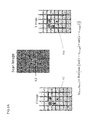
- FIG. 3B shows a second example of a reference pattern that may be used in a page-velocity estimation method according to an example of the invention
- FIG. 4 is a flow diagram illustrating a page-velocity estimation method according to an example of the invention.
- FIG. 5 is a flow diagram illustrating an example of a crossing-point detection process that may be used in the method of FIG. 4 ;
- FIG. 6 is a flow diagram illustrating an example of a crossing-point matching process that may be used in the method of FIG. 4 ;
- FIG. 7 is a flow diagram illustrating an example of a process, that may be used in the method of FIG. 4 , for estimating page velocity based on displacements between points in a reference pattern and points in a scan image generated by imaging the reference pattern;
- FIGS. 8A and 8B are diagrams illustrating an example of a process employed by a processor to find, on two double grey-level images, a set of pixels having the closest grey level to certain line coordinates;
- FIG. 10 is a diagram illustrating smoothing of result data
- FIG. 11 is a schematic representation of an imaging device that can implement page-velocity estimation methods according to an example of the invention.
- FIG. 1 is a schematic representation of certain components in one example of printer 1 in which the page velocity estimation method of the present example is employed.
- the printer 1 includes a page transport mechanism 3 , 3 ′ (here illustrated in a highly simplified form consisting of two pairs of rollers) for transporting individual pages P from a supply zone 4 through the printer 1 .
- the printer 1 further includes a writing module 6 for creating markings on a page P as it is transported through a printing zone in the printer 1 .
- the writing module 6 may use any convenient technology for creating markings on the page P including but not limited to ink jet printing, laser printing, offset printing, and so on.
- the in-line sensing unit 8 is a TDI unit and includes a multi-line array of contiguous sensors each line of sensors being positioned to image a line extending at least the whole width of a page P.
- the array may include a large number of individual sensors (e.g. of the order of thousands of individual sensors) in the case of a large-format commercial printing device.
- the signals from the different lines of sensors are averaged to produce image data for a line of the scan image.
- the printer 1 further includes a processor 10 connected to the transport mechanism 3 , 3 ′, to the writing module 6 and to the sensing unit 8 , via respective connections 11 , 12 and 13 .
- the processor 10 is arranged to control operation of the printer 1 and, in particular, to control feeding of pages through the printer 1 by the transport mechanism 3 , 3 ′, printing on pages by the writing module 6 and scanning of pages by the sensing unit 8 .
- the processor 10 may supply printing data (based on a digital representation of a target image) to the writing module 6 via the connection 12 .
- the processor 10 may be connected to a control unit C which supplies digital representations of target images to be printed by the printer 1 .
- the control unit C may form part of another device including but not limited to a portable or desktop computer, a personal digital assistant, a mobile telephone, a digital camera, and so on.
- the processor may be arranged to print target images based on digital representations supplied from a recording medium (not shown), e.g. a disc, a flash memory, and so on.
- the processor 10 in printer 1 is configured to perform a number of diagnostic and/or calibration functions.
- the processor 10 may be configured to compare a scan image of a given page P with a digital representation of a target image that was intended for printing on page P. Discrepancies between the scan image and the target image may provide information enabling the processor 10 to diagnose malfunctions and/or defects in the operation of the printer 1 and may allow the processor 10 to perform control to implement remedial action (see below).
- the processor 10 is arranged to construct the scan image based on a number of assumptions, notably, assuming that each page P is transported through the printing zone at a constant linear velocity in a direction D parallel to the lengthwise direction of the page (this corresponds to the y direction in the plane of the page). More particularly, in this example the processor 10 is arranged to position the line images generated by the sensing unit 8 in successive detection periods at respective positions that are spaced apart from each other in the y direction (in the scan image plane) by a distance that depends on the time interval between successive detection periods and on the nominal page velocity through the printing zone.
- the nominal page velocity is set so that the line images generated for successive detection periods are positioned one pixel apart in the scan image (i.e. the nominal page velocity is set to make a continuous scan image). For example, if successive detection periods are 1/1600 second apart the page velocity may be set to 1600 pixels per second so that the adjacent line images in the scan image may be positioned 1 pixel apart in the direction of page travel (here the y direction).
- the processor 10 translates each line image produced by the sensing unit 8 in a given detection period into a line of pixels whose positions in the x direction in the scan image are based on the positions of the sensors in the sensing array.
- FIG. 2 illustrates an example of a case where distortion arises in a scan image relative to the original image on a page P imaged by the scanning unit 8 of printer 1 .
- the original image on the page P includes dots arranged in rows across the page width, the rows are parallel to each other and the spacing between rows is uniform.
- the page velocity varies as the page P is transported past the sensing unit 8 of printer 1 so that the scan image does not faithfully reproduce the positions of the dots as in the original image.
- the scan image still shows rows of dots extending across the page width but the spacing between the rows is no longer uniform.
- the spacing d between dots in the same line of the scan image i.e. dots imaged during the same detection period
- the processor 10 may not be able to find a match in the reference image to the pixel intensities occurring along a line in the scan image. Further, in such a case the processor 10 may increase the size of the region in the scan image that is used in the estimation process but this leads to a loss in precision of the velocity estimate.
- the printer 1 is operable in a page-velocity estimation mode in which the processor 10 implements a page velocity estimation method that makes use of a reference pattern 20 to enable an estimate to be made of the relative velocity of the page relative to the scanning unit 8 during the imaging process.
- the page velocity estimation mode may be set explicitly for the printer 1 , for example by a user operating a control element (not shown), or selecting a menu option, provided for this purpose on the printer 1 .
- the printer may be arranged to enter page velocity estimation mode in some other manner, for example automatically when the printer implements a calibration method or diagnostic method.
- a page bearing a reference pattern 20 is transported past the in-line sensing unit 8 of the printer 1 : the reference pattern may be a pre-existing pattern that is already present on the page P when the page enters the printing zone, or the processor may be arranged to control the writing module 6 to print the reference pattern 20 on a blank page based on a digital representation of the reference pattern.
- the processor 10 is supplied with a digital representation of the reference pattern 20 used in page-velocity estimation mode.
- the in-line sensing unit 8 images the reference pattern 20 as the page is transported through the printer 1 and the processor 10 is arranged to produce an estimate of page velocity by processing image data generated by the sensing unit 8 and a digital representation of the reference pattern that was imaged to produce the image data.
- the reference pattern may be a grid pattern 20 a as illustrated in FIG. 3A , formed by plural lines that extend parallel to the page length direction and intersect plural lines extending in the page width direction, the intersecting lines being perpendicular to each other. Other forms of reference pattern may be used, as discussed below.
- FIG. 4 is a flow diagram illustrating steps in one example of page-velocity estimation method according to the invention.
- the processor 10 generates a scan image of the reference pattern imaged by the sensing unit 8 .
- the processor 10 implements processing of the scan image data to detect positions of crossing points in the scan image, that is, the positions in the scan image plane of points where perpendicular lines intersect.
- the processor 10 implements processing to match specific crossing points that have been detected in the scan image to crossing points in a digital representation of the reference pattern.
- step S 404 of the method the processor 10 performs processing to determine relationships between positions of given crossing points in the scan image and the positions of matched crossing points in the reference pattern.
- page velocity is estimated in a method which involves determining the registration between pixels in the scan image and points on the imaged substrate by finding points in the scan image where perpendicular lines cross each other and matching the locations of these detected crossing points to positions of crossing points in a reference image.
- Crossing points of this kind have characteristic features and it is possible to find the locations of such crossing points in the scan image accurately even in cases where the scan image is produced by a low-cost scanner having a relatively low signal-to-noise ratio.
- the page-velocity estimation method of this example produces accurate page velocity estimates even when low-cost scanning units are used to produce the scan image, thus enabling more reliable page transportation estimation, scanner calibration and image registration.
- Reference patterns using other dispositions of crossing points may also be used in the present example page-velocity estimation method, provided that such reference patterns include plural crossing points each formed of intersecting perpendicular lines.
- Methods according to examples of the invention may employ different reference patterns having crossing points formed from line portions of different sizes and/or having crossing points that are spaced relatively closer or further apart from each other.
- the reference pattern includes numerous crossing points spaced close to one another this tends to improve the accuracy of detection of deviations of the page velocity from the nominal value.
- the component elements in the reference pattern are physically small it is possible to include a relatively large number of these components in a small space.
- Crossing points can be formed small in the reference pattern and yet they are highly detectible: a cross pattern gives high measurement accuracy (in the directions corresponding to the constituent line portions) as a function of the dimensions of those line portions.
- the maximum permissible distance between crossing points in the reference pattern depends on the nominal page velocity and the period of time over which it is desired to detect velocity changes.
- the minimum permissible distance between crossing points in the reference patterns may be set based on the size of convolution kernels that may be used for detection of crossing points in a scan image of the reference pattern produced by the sensing unit (see below). In an example of the method wherein nominal page velocity was 1600 pixels per second it was found that the accuracy of the page velocity estimates improved when both the lengths of the line portions corresponding to the convolution kernels and the minimum spacing between neighbouring crossing points in the reference pattern were 50 pixels or greater.
- processor 10 may implement to perform step S 402 of FIG. 4 to determine the locations, in the scan image, of places where perpendicular lines cross each other will now be described. An overview of the example method will be given before discussing steps therein with reference to the flow diagram of FIG. 5 .
- the processor 10 first computes convolution products. More particularly, the processor 10 computes a given convolution product by first convolving the scan image with a first kernel (that corresponds to a first straight line portion) to produce a first convolution result, then convolving the scan image with a second kernel (that corresponds to a second straight line portion perpendicular to the first straight line portion) to produce a second convolution result, and then multiplying the first and second convolution results to produce a convolution product.
- the convolution product contains peaks of intensity at locations in the scan image plane that correspond to crossing points that are formed from line portions oriented in the same directions as the first and second straight line portions of the convolution kernels.
- each peak of intensity coincides with the point of intersection of the lines forming a crossing point.
- the processor 10 may be arranged to detect the locations, in the scan image plane, of the centres of these intensity peaks and to register these locations as the centres of crossing points in the scan image.
- the processor 10 When the processor 10 performs the example method to determine locations of crossing points in a scan image of a reference pattern of the types illustrated in FIGS. 3A and 3B , where each crossing point is formed from line portions that extend in the page length and page width directions, it may be expected that the scan image will contain crossing points formed from line portions that extend in the vertical and horizontal directions in the plane of the scan image (assuming that the page bearing the reference pattern travelled past the scanning unit 8 in the lengthwise or widthwise direction of the page). Thus, the locations of the crossing points may be found in the scan image using convolution kernels that correspond to straight line portions oriented in the vertical and horizontal directions in the scan image plane.
- the processor 10 may be arranged to compute plural convolution products for a given scan image, and in the computation of each convolution product the processor may employ kernels that correspond to first and second straight line portions that are in a slightly different orientation in the scan image plane as compared to the orientations used in the computations of the other convolution products (whilst still being perpendicular to each other). The processor 10 may then be arranged to identify which of the convolution products contains peaks of maximum intensity (that is, peaks of intensity greater than that of peaks in the other convolution products).
- the identified convolution product should correspond to the case where the orientations of the straight line portions of the convolution kernels best match with the orientations of the lines forming the crossing points in the scan image and, thus, the orientation of the straight line portions in these convolution kernels provides the processor 10 with information regarding the likely skew angle of the page bearing the reference pattern as that page was transported relative to the scanning unit 8 .
- the processor 10 may be arranged not only to determine page skew based on the identified maximum-peak-intensity convolution product but also to identify the locations of crossing points in the scan image by processing the identified maximum-peak-intensity convolution product preferentially rather than processing other convolution products. This improves the accuracy of the crossing-point locations determined by the professor 10 .
- step S 503 of this example method the processor 10 next performs a convolution between the scan image data and a kernel that corresponds to a line segment oriented at angle ⁇ +90° relative to the vertical in the scan image, producing a result designated CIhk. It will be understood that the line segments used in the convolutions of steps S 502 and S 503 are perpendicular to each other.
- step S 504 of the example method the processor 10 multiplies together the results of the convolution processes of steps S 502 and S 503 to give a product designated Pk.
- step S 505 of FIG. 5 the processor 10 checks whether the counting variable k has reached a predetermined maximum value k max . If the counting variable k has not yet reached the maximum value then the processor increments the counting variable k by 1 and increases angle ⁇ by an increment ⁇ (step S 506 of FIG. 5 ) then repeats the steps S 502 to S 505 . It will be understood that the incrementing of the count variable k allows the orientation of the line segment used in the convolution process of step S 502 to be gradually shifted from ⁇ 0 to ⁇ 0 +( ⁇ k max ), in steps of ⁇ degrees.
- Steps S 508 and S 509 of FIG. 5 illustrate one example of a technique that may be used for determining the locations of the centres of the intensity peaks in the synthetic image.
- the processor 10 converts the two-dimensional synthetic image data into a binary image, i.e. an image in which each pixel takes one of only two values (corresponding either to black or white).
- a convenient technique for performing the conversion to a binary image consists in defining a local threshold value and assigning black or white values to pixels of the synthetic image depending on whether or not their value exceeds the local threshold value (step S 508 in FIG. 5 ).
- the processor 10 implements a recursive search procedure in which a crossing point C(n,m) in the scan image that has already been matched to a crossing point (n,m) in the reference pattern serves as a jumping off point for defining a search region in the scan image where the processor will look for a neighbouring crossing point, notably where the processor will look for a crossing point corresponding to (n+1,m) or (n,m+1) in the reference pattern.
- the page bearing the reference pattern was supposed to move in the page-length direction relative to the sensing unit during the imaging process.
- a first step S 601 the processor 10 locates, in the scan image, the crossing point that is located closest to the top left-hand corner of the scan image plane.
- This crossing point shall be designated C(0,0).
- the processor is configured to assume that crossing point C(0,0) in the scan image is an image of a crossing point (0,0) that is located at the top left-hand corner in the reference pattern.
- step S 602 of the FIG. 6 method the processor registers crossing point C(0,0) in the scan image as a match to crossing point (0,0) in the reference pattern.
- step S 603 the processor 10 sets coordinates (n,m) to the value (1,0); this defines a crossing point (1,0) in the reference pattern as a target for which the processor 10 will now look for a match in the scan image. It will be noted that the crossing point (1,0) in the reference pattern, which is the next target for matching, is one of the nearest neighbours of the crossing point (0,0) in the reference image which was matched in the preceding step of the method.
- step S 605 the processor defines a search region centred on the predicted position of C(1,0) and checks whether any of the crossing points that have been identified in the scan image occur within this search region.
- the size of the search region is d N by d M , centred on the predicted location of C(1,0).
- step S 607 finds in step S 607 that n ⁇ n max then the value of n is increased by one in step S 608 and the flow returns to step S 604 so that the processor can search for a crossing point in the scan image that matches to the next crossing point to the right.
- step S 609 a check is made in step S 609 whether the value of m has reached a maximum value m max , i.e. the processor checks whether the matching process has reached the bottom of the page/image.
- step S 609 If the processor finds in step S 609 that m ⁇ m max then the value of m is increased by one in step S 610 —so that the processor can search for a crossing point in the scan image that matches to a crossing point in the next row down the reference pattern—and the value of n is re-set to 0 so that the processor will search for a crossing point in the scan image that matches to the left-hand crossing point in this next row down the reference pattern.
- the processor continues implementing the loops S 604 -S 609 via S 608 and S 610 to perform the recursive search process systematically searching for crossing points in the scan image that match to the crossing points positioned left-to-right in the rows of the reference pattern and in the different rows from top-to-bottom of the reference pattern.
- the search directions may be modified if the start point of the matching process is not the top left-hand corner.
- the processor 10 After the processor 10 has searched for a match for crossing point (n max ,m max ) of the reference pattern the results of steps S 607 and S 609 of FIG. 6 will both be “yes” and the matching process comes to an end. By this time the processor has generated a list of crossing points in the scan image that match to respective specific crossing points in the reference pattern.
- the differences between the locations of crossing points in the scan image plane and the locations of the matched crossing points in the reference pattern plane encode information regarding how the page velocity has varied during the imaging process.
- the locations of the crossing points in the scan image according to the coordinate system of the scan image plane can be determined, and the locations of the crossing points in the reference pattern according to the coordinate system of the reference pattern are already known (from the digital representation of the reference pattern). Accordingly, by suitable processing the processor 10 can extract information regarding how the page velocity has varied during the imaging process from the relationships between the locations of crossing points in the scan image plane and the locations of the matched crossing points in the reference pattern plane.
- the processor 10 may determine relationships between pixels in the scan image and points in the reference pattern that were imaged to generate the points in the scan image, implementing step S 404 of FIG. 4 , shall now be described.
- the processor 10 is arranged to calculate non-linear transformation parameters relating the crossing points' locations in the scan image to their locations in the reference pattern.
- the non-linear transformation parameters are calculated making use of the relative spatial positions of the matched crossing points in the scanned and reference images.
- a displacement between a given crossing point in the reference pattern and the matched crossing point in the scan image can arise from a combination of different translational and rotational movements.
- a point (y,x) in the reference pattern may be shifted to a location (y′,x′) in the scan image by either of the following:
- the calculations applied by the processor 10 are based on certain assumptions. Firstly, it is assumed that for small areas in the reference pattern and scan image:
- the matrix of coefficients (a1 a2 a6 a3 a4 a8) in relation (12) takes the place of matrix R above
- the second matrix to the right of the equals sign in relation (12) takes the place of matrix S above
- the processor 10 may determine the inverse transformations needed to transform the coordinates (x′,y′) of points in the reference pattern plane to coordinates (x,y) of corresponding points in the scan image plane, as follows.
- ⁇ ⁇ A ( a ⁇ ⁇ 3 ⁇ a ⁇ ⁇ 5 a ⁇ ⁇ 7 + a ⁇ ⁇ 1 ⁇ a ⁇ ⁇ 6 a ⁇ ⁇ 7 )
- the processor 10 can determine values for the coefficients a1 to a8 using the coordinates of matched crossing points as described above, the processor 10 can perform transformations from coordinates (x′,y′) in the reference pattern to coordinates in the scan image (x,y) using the coefficient values and using relations (18) and (14) above. Moreover, the (x,y) coordinates in the scan image that corresponds to given (x′,y′) coordinates in the reference pattern can be determined to sub-pixel accuracy.
- step S 701 of FIG. 7 the processor identifies positions of points in the reference pattern that correspond to equal scan time lines (in other words, points in the reference pattern that were imaged at the same time).
- step S 702 of FIG. 7 the processor then computes estimates of page velocity based on the positions of pixels in the reference pattern that were imaged at the same time, and based on knowledge of the time when those pixels were imaged.
- FIGS. 8A and 8B illustrate how the processor finds—on the two double grey-level images—the set of pixels having the closest grey level to the line coordinate (y and x).
- the processor 10 For a given pixel (x r ,y r ) in the scan image (notably a pixel that is on a target equal-scan-time line), the processor 10 searches for a common pixel location (i,j) in the Y and X grey-level images where the grey levels, in the respective grey-level images, are as close as possible to the coordinate values (x r ,y r ). To do this, the processor 10 predicts a location PV in the Y image where it might be expected that the grey level will correspond to x r and predicts a location PW in the X image where it might be expected that the grey level will correspond to y r (in one example PV and PW may be set equal to (x r ,y r )).
- the grey levels at the predicted points PV, PW may not, after all, be the values that correspond to x r and y r so, in each of the grey-level images, a search is performed in a search region around the predicted point, looking in the two images for a common pixel location where the grey levels are as close as possible to x r and y r .
- the location of this common pixel corresponds—to the nearest pixel—to the pixel location (x r ′,y r ′) in the reference image that gave rise to the pixel (x r ,y r ) in the scan image.
- FIG. 9 illustrates how the processor uses bilinear interpolation, using the neighbours of the common pixel found by the method of FIGS. 8A and 8B , to find the locations (to sub-pixel precision) of points in the reference pattern that correspond to the equal scan-time lines.
- the formulae used in the bilinear interpolation are shown in FIG. 9 .
- the processor 10 may compute values for page velocity from the equal scan time line data (step S 702 in FIG. 7 ).
- the computed velocity values may include values v x corresponding to translational velocity in the x direction, values v y corresponding to translational velocity in the y direction, and values w corresponding to rotational velocity in the plane of the page.
- the processor 10 may compute plural sets of velocity values for the page, and each set of velocity values may relate to a short time interval during the imaging of the reference pattern, for example a time interval between two successive detection periods (i.e. a time interval between generation of two successive line images by the in-line scanning unit 8 ).
- the result data may be smoothed as illustrated in FIG. 10 using Savitzky-Golay convolution and based on assumptions that, in a short time, v x and v y are constant, and x 0 and y 0 are constant, and any acceleration derives from change in the rotational velocity w.
- Vx and v y are calculated according to the neighbour scan time lines found as discussed above. Local calculations are used for each area, computing QS T (SS T ) ⁇ 1 as described.
- FIG. 10 shows relations that derive from the assumption of constant velocity over a small area in the image (in which the w values are extracted from processing of previous stages described above), and relations that derive from the assumption of constant acceleration over a small area.
- the processor 10 may be configured to use the above example method to estimate plural sets of page velocity values v x , v y and w, each set of values being applicable during a different time interval occurring during the imaging process. If these time intervals are spaced regularly over the imaging period then the processor generates page velocity data that represents a profile of how the page velocity varied during the imaging process.
- the processor 10 When the processor 10 is arranged to compute sets of velocity estimates for a small number of time intervals during the imaging process this has the advantage of reducing the computational load on the processor 10 .
- the estimated velocity values can be used to diagnose and/or correct problems in a mechanism which transports the substrate relative to the sensing unit or which transports the sensing unit relative to the substrate.
- the estimated velocity values may enable a processor associated with the scanning unit to identify regions in the scan image where the relative velocity of displacement between the substrate and the sensing unit is stable and/or close to a nominal direction and magnitude. Such regions may then be used by the processor in preference to other regions when the processor performs functions such as calibration that involve processing of scan image data.
- the processor 10 of the printing device 1 of FIG. 1 may be arranged to use page-velocity estimates produced by implementing the above-described page-velocity estimation methods in a diagnosis method that diagnoses imperfections in the page transport mechanism 3 , 3 ′ that transports pages past the scanning unit 8 . Based on the page velocity estimates, the processor 10 may diagnose a particular imperfection in the page transport mechanism 3 , 3 ′. The processor 10 may be arranged to output information about the result of the diagnosis, for example so that the information can be logged, displayed to a user, and so on. The processor 10 may be arranged to implement remedial action to correct the diagnosed imperfection. Some examples of such remedial action will be given below but it is to be understood that the invention is not limited to these examples.
- the processor 10 may determine, based on the page velocity estimates, that there is a periodic variation in the magnitude of the velocity at which the page transport mechanism 3 , 3 ′ feeds pages past the scanning unit 8 , or there is a systematic deviation from the nominal magnitude of page velocity.
- the processor 10 may be arranged to implement remedial action by appropriate control of a servo mechanism (not shown) that drives the page transport mechanism 3 , 3 ′, notably control to adjust the magnitude of the page-feed speed to counteract the diagnosed periodic variation or systematic deviation from nominal speed.
- the processor may use page velocity estimation methods according to examples of the invention to determine the maximum image correlation length, that is, the maximum area of the image where there is no difference between the pattern on the imaged substrate and the scan image.
- an imaging device 101 according to one example of the invention will now be described with reference to FIG. 11 .
- the imaging device 101 is a flat-bed scanner, but the invention is not limited to imaging devices of this type.
- a base portion 102 of the scanner provides a transparent surface 103 for reception of a page P to be imaged.
- a lid portion 104 of the scanner 101 is supported by side portions 104 and can be raised and lowered to enable pages to be placed on and removed from the transparent surface 103 .
- the scanner 101 includes an in-line scanning unit 106 that is mounted for movement in a direction S from one end of the surface 103 to the other so that it can image the whole surface of a page P that is present on the transparent surface 103 , and for return in the reverse direction.
- the in-line scanning unit 106 carries a light source 108 to provide light to illuminate the surface of the page P facing the transparent surface 103 .
- the flat-bed scanner 101 illustrated in FIG. 11 includes a processor 110 arranged to control the components of the scanner 101 and to receive scan image data from the sensing unit 106 .
- the processor 110 of the imaging device 101 of FIG. 11 may be arranged to communicate with an external device C, for example to transmit to C image data generated by the sensing unit 106 .
- the processor 110 of the imaging device 101 of FIG. 11 may be arranged to implement any of the page-velocity estimation methods described above.
- the processor 110 may be arranged to perform the selected page-velocity estimation method by loading an appropriate application program or routines, for example from a memory (not shown) associated with the imaging device 101 , of from any other convenient source (uploading via a network, loading from a recording medium, and so on).
- the processor 110 of the imaging device 101 of FIG. 11 may be arranged to use page-velocity estimates produced by implementing the above-described page-velocity estimation methods in calibration methods that calibrate the scanning unit 106 .
- the processor 110 may be arranged (as mentioned above in connection with the processor 10 of the printing device 1 ) to select particular regions of the scan image for use in a calibration process: these may be image regions where the processor 110 has determined there will be no difference between the scan image and the original pattern on the substrate.
- page-velocity estimation methods may be used to provide page-velocity information for use in other calibration methods including but not limited to:
Landscapes
- Image Processing (AREA)
Abstract
Description
-
- the invention is not limited to the case where the method is performed in a printer or in another apparatus having a function of printing or otherwise recording a pattern on a substrate; the method may be performed in general in any apparatus where an in-line sensing device performs line-based imaging of patterns on a substrate as a relative displacement occurs between a sensing unit of the imaging device and the substrate, for example, in a scanner or other imaging device;
- the invention is not limited to use of an on-board processor; the processor may be in a separate device that receives various signals from the apparatus that incorporates the sensing unit that images the substrate;
- the invention is not limited to the case where the substrate consists of individual pages or sheets; methods according to examples of the invention may be applied irrespective of the form the substrate takes including but not limited to: a sheet or page, a continuous or semi-continuous web, and so on, moreover the material from which the substrate is formed is not particularly limited; and
- the invention is not limited to the case where the substrate is transported relative to the sensing unit; the sensing unit may be transported relative to the substrate, or the relative displacement may result from motion both of the substrate and of the sensing unit.
θ=μ+2σ
where μ is the mean value taken by the pixels in a small area local to the subject pixel, and σ is the standard deviation of the values taken by the pixels in this small area local to the subject pixel. This amounts to searching in the synthetic image for local maxima. In the present example, a pixel in the synthetic image is converted to a white pixel in the binary image if the intensity of this pixel in the synthetic image is greater than θ, otherwise the pixel is converted to a black pixel in the binary image. The binary image produced by this technique contains regions where white pixels are connected together in blob-shaped regions, on a black background. In the method according to the present example, where the binary image contains blob-shaped regions where white pixels are connected together, a list of the connected pixels can be generated in a simple manner by making use of a function designated “bwlabel” provided in the numerical programming environment MATLAB developed by The MathWorks Inc.
-
- a first rotation of the page around a centre of rotation (a,b) by a first angle, or
- a translation of the page in a first direction, followed by a different rotation of the page around a centre of rotation (c,d).
Moreover, in principle a movement caused by a translation followed by a rotation does not produce the same displacement as a rotation followed by a translation. Accordingly, a strategy is needed in order to be able to disentangle rotational and translational movements of the page.
-
- all the points in the small area are imaged at approximately the same time so that the displacement of a point in this small area that results from a translation followed by a rotation is approximately the same as the displacement the point experiences resulting from a rotation followed by a translation,
- the orientation angle of the page is constant when the small area is imaged (i.e. any rotation of the page during imaging of the small area is a rotation through a small angle, such that the sine of the angle approximates to the angle itself and the cosine of the angle approximates to 1),
- points in the small area that are at different positions in the x-direction (perpendicular to the nominal direction of page advance) are sufficiently close together that they are imaged by the in-
line sensing unit 8 during a common detection interval and, thus, the page velocity is the same when all these points were imaged, - points in the small area that are at different positions in the y-direction (parallel to the nominal direction of page advance) are sufficiently close together that they are imaged by the in-
line sensing unit 8 during detection intervals that are close together in time and, thus, the page velocity is approximately the same when all these points were imaged, and thus - it can be assumed that the page velocity is constant during imaging of the small area.
Secondly, it is assumed that displacement of the page P is displacement of a rigid body, i.e. it is assumed that the dimensions of the page do not change during the imaging process (any potential folding or kinking of the page is disregarded).
y′=y+(x−x 0)(wt+Ø)+v y t+y c (1)
x′=(y−y 0)(−wt−Ø)+x+v x t+x c (2)
where the point in question is imaged at a time t, (x0,y0) are the coordinates in the scan image plane of the centre of rotation of rotational movement at time t, w is the page's rotational velocity at time t, vy is the page's translational velocity in the y direction at time t, vx is the page's translational velocity in the x direction at time t1, xc is the shift in the x-direction of the point's position between the reference pattern and the scan image, yc is the shift in the y-direction of the point's position between the reference pattern and the scan image, and Ø is the rotational angle, that is the angle of the page at time t (relative to the nominal page orientation).
y′=y+(x−x 0)Ø+(x−x 0)wyc+v y yc+y c (3)
x′=(y−y 0)(−Ø)+(y−y 0)(−wyc)+x+v x yc+x c (4)
y′=cwyx+(1−cwx 0 +cv y)y+Øx+(Øx 0 +y c) (5)
x′=−cwy 2+(−Ø+cv x +cwy 0)y+x+(Øy 0 +x c) (6)
and using symbols a1 to a8 to replace the coefficients of the different terms in relations (5) and (6), relations (5) and (6) can be rewritten as relations (7) and (8) below:
y′=a1yx+a2y+a3x+a4 (7)
x′=a5y 2 +a6y+a7x+a8 (8)
However, a comparison of relations (5) and (7) above with relations (6) and (8) shows that a1=−a5. Taking this fact into account, relations (9) and (10) can be combined into relation (11) below.
QS T =RSS T and QS T(SS T)−1 =R
where ST is the transform of matrix S and (SST)−1 is the inverse of (SST). Thus, the matrix R can be found by computing QST (SST)−1. If the matrix to the left of the equals sign in relation (12) takes the place of matrix Q above, the matrix of coefficients (a1 a2 a6 a3 a4 a8) in relation (12) takes the place of matrix R above, and the second matrix to the right of the equals sign in relation (12) takes the place of matrix S above, it will be seen that the matrix of coefficients (a1 a2 a6 a3 a4 a8) can be determined by computing QST (SST)−1.
a1yx+a2y−y′+a3x+a4=0 (13)
and relation (8) above may be rewritten as relation (14) below:
Substituting the right-hand side of relation (14) for parameter x in relation (13) yields relation (15) below:
and this may be rewritten as relation (16) below:
which is a quadratic equation. Solving this quadratic equation for y yields relation (18) below:
-
- The
processor 10 builds two double grey level images according to location (y and x) found in the previous stage. In each of these images the color corresponds to pixel location in the scan image. - The processor extracts sets of constant-y lines' coordinates (equal scan-time lines).
- For each of the equal scan-time lines, the processor finds—on the two double grey-level images—the set of pixels having the closest grey level to the line coordinate (y and x).
- Using bilinear interpolation, the processor finds the locations (to sub-pixel precision) of points in the reference pattern that correspond to equal scan-time lines.
- The
y′=y+(x−x 0)(Ø+wΔt)+v y Δt+y c (19)
x′=(y−y 0)(−Ø−wΔt)+x+v x Δt+x c (20)
where Δt corresponds to the interval between the scan times of two equal-scan-time lines in the scan image (which may be separated from each other by one or more than one lines in the scan image). It will be seen that relations (19) and (20) resemble relations (3) and (4) above. Coordinate data relating to the whole of an equal scan time line can be transformed according to relations (21) and (22) below:
where ay=1, by=(Ø+wΔt), and cy=vyΔt+yc−x0(Ø+wΔt) and
where ax=1, bx=−(Ø+wΔt), and cx=vxΔt+xc+y0(Ø+wΔt)
b yT+Δt −b yT=(Ø+wΔt)−(Ø+0w)=wΔt (24)
c yT+Δt −c yT =v y Δt+y c −x 0(Ø+wΔt)−(
c xT+Δt −c xT =v x Δt+x c +y 0(Ø+wΔt)−(
It will be seen that page velocity values vx, vy and w appear in the results. These are estimates of velocity values applicable during the interval from t=T to t=T+Δt (which may be the interval between successive scan times or a somewhat longer interval).
Claims (16)
Priority Applications (1)
| Application Number | Priority Date | Filing Date | Title |
|---|---|---|---|
| US13/872,299 US9315047B2 (en) | 2013-04-29 | 2013-04-29 | Velocity estimation methods, and imaging devices and printing devices using the methods |
Applications Claiming Priority (1)
| Application Number | Priority Date | Filing Date | Title |
|---|---|---|---|
| US13/872,299 US9315047B2 (en) | 2013-04-29 | 2013-04-29 | Velocity estimation methods, and imaging devices and printing devices using the methods |
Publications (2)
| Publication Number | Publication Date |
|---|---|
| US20140320565A1 US20140320565A1 (en) | 2014-10-30 |
| US9315047B2 true US9315047B2 (en) | 2016-04-19 |
Family
ID=51788901
Family Applications (1)
| Application Number | Title | Priority Date | Filing Date |
|---|---|---|---|
| US13/872,299 Expired - Fee Related US9315047B2 (en) | 2013-04-29 | 2013-04-29 | Velocity estimation methods, and imaging devices and printing devices using the methods |
Country Status (1)
| Country | Link |
|---|---|
| US (1) | US9315047B2 (en) |
Cited By (1)
| Publication number | Priority date | Publication date | Assignee | Title |
|---|---|---|---|---|
| US20200210792A1 (en) * | 2017-09-26 | 2020-07-02 | Hp Indigo B.V. | Adjusting a colour in an image |
Families Citing this family (4)
| Publication number | Priority date | Publication date | Assignee | Title |
|---|---|---|---|---|
| JP5970970B2 (en) * | 2012-06-13 | 2016-08-17 | 富士通株式会社 | Image processing apparatus, method, and program |
| US11620811B2 (en) * | 2020-04-27 | 2023-04-04 | The Boeing Company | Automated measurement of positional accuracy in the qualification of high-accuracy plotters |
| CN115849113A (en) * | 2022-11-23 | 2023-03-28 | 宁德时代新能源科技股份有限公司 | Roller, spot inspection method and apparatus, web conveying apparatus, and medium |
| CN118151501B (en) * | 2024-05-11 | 2024-07-23 | 魅杰光电科技(上海)有限公司 | Overlay error measurement method, device and system based on optical flow method and storage medium |
Citations (8)
| Publication number | Priority date | Publication date | Assignee | Title |
|---|---|---|---|---|
| US6317219B1 (en) | 1997-09-29 | 2001-11-13 | Samsung Electronics Co., Ltd. | Method and apparatus for compensating for a distortion between blocks of a scanned image |
| US20050052704A1 (en) | 2003-08-14 | 2005-03-10 | Samsung Electronics Co., Ltd. | Image data compensation scanner, medium, and method |
| US20090317104A1 (en) * | 2007-06-21 | 2009-12-24 | Tsutomu Katoh | Image forming apparatus |
| US20100123752A1 (en) * | 2008-11-20 | 2010-05-20 | Xerox Corporation | Printhead Registration Correction System and Method for Use with Direct Marking Continuous Web Printers |
| US20110007371A1 (en) | 2008-12-17 | 2011-01-13 | Canon Kabushiki Kaisha | Measuring separation of patterns, and use thereof for determining printer characteristics |
| US20110316925A1 (en) * | 2010-06-28 | 2011-12-29 | Hirofumi Saita | Inkjet printing apparatus and printing method of inkjet printing apparatus |
| US20120206531A1 (en) | 2011-02-14 | 2012-08-16 | Xerox Corporation | Test pattern less perceptible to human observation and method of analysis of image data corresponding to the test pattern in an inkjet printer |
| US8363261B1 (en) | 2008-08-13 | 2013-01-29 | Marvell International Ltd. | Methods, software, circuits and apparatuses for detecting a malfunction in an imaging device |
-
2013
- 2013-04-29 US US13/872,299 patent/US9315047B2/en not_active Expired - Fee Related
Patent Citations (8)
| Publication number | Priority date | Publication date | Assignee | Title |
|---|---|---|---|---|
| US6317219B1 (en) | 1997-09-29 | 2001-11-13 | Samsung Electronics Co., Ltd. | Method and apparatus for compensating for a distortion between blocks of a scanned image |
| US20050052704A1 (en) | 2003-08-14 | 2005-03-10 | Samsung Electronics Co., Ltd. | Image data compensation scanner, medium, and method |
| US20090317104A1 (en) * | 2007-06-21 | 2009-12-24 | Tsutomu Katoh | Image forming apparatus |
| US8363261B1 (en) | 2008-08-13 | 2013-01-29 | Marvell International Ltd. | Methods, software, circuits and apparatuses for detecting a malfunction in an imaging device |
| US20100123752A1 (en) * | 2008-11-20 | 2010-05-20 | Xerox Corporation | Printhead Registration Correction System and Method for Use with Direct Marking Continuous Web Printers |
| US20110007371A1 (en) | 2008-12-17 | 2011-01-13 | Canon Kabushiki Kaisha | Measuring separation of patterns, and use thereof for determining printer characteristics |
| US20110316925A1 (en) * | 2010-06-28 | 2011-12-29 | Hirofumi Saita | Inkjet printing apparatus and printing method of inkjet printing apparatus |
| US20120206531A1 (en) | 2011-02-14 | 2012-08-16 | Xerox Corporation | Test pattern less perceptible to human observation and method of analysis of image data corresponding to the test pattern in an inkjet printer |
Non-Patent Citations (2)
| Title |
|---|
| Michael T. Snella, Drift Correction for Scanning-Electron Microscopy submitted to the Department of Electrical Engineering and Computer Science in partial fullfillment of the requirements for the degree of Master of Engineering in Electrical Engineering and Computer Science at the Massachusetts Institute of Technology, Sep. 2010 (92 pages). |
| Oren Haik et al., Superresolution reconstruction of a video captured by a vibrated time delay and integration camera, Journal of Electronic Imaging 15(2), 023006 (Apr.-Jun. 2006) (12 pages). |
Cited By (2)
| Publication number | Priority date | Publication date | Assignee | Title |
|---|---|---|---|---|
| US20200210792A1 (en) * | 2017-09-26 | 2020-07-02 | Hp Indigo B.V. | Adjusting a colour in an image |
| US10878300B2 (en) * | 2017-09-26 | 2020-12-29 | Hp Indigo B.V. | Adjusting a colour in an image |
Also Published As
| Publication number | Publication date |
|---|---|
| US20140320565A1 (en) | 2014-10-30 |
Similar Documents
| Publication | Publication Date | Title |
|---|---|---|
| US9315047B2 (en) | Velocity estimation methods, and imaging devices and printing devices using the methods | |
| US9848098B2 (en) | Image forming apparatus capable of correcting image formation position | |
| US7567267B2 (en) | System and method for calibrating a beam array of a printer | |
| US8384911B2 (en) | Measurement device and measurement method | |
| EP2588836B1 (en) | Three-dimensional measurement apparatus, three-dimensional measurement method, and storage medium | |
| US20110149331A1 (en) | Dynamic printer modelling for output checking | |
| JP5493105B2 (en) | Object dimension measuring method and object dimension measuring apparatus using range image camera | |
| JPH06238952A (en) | Method for printing image in specific positional relation to preprinted register mark | |
| US20090003729A1 (en) | Fiducial artifact detection and compensation algorithm | |
| CN110823124A (en) | Optical displacement meter | |
| US20040120603A1 (en) | Enhancing the resolution of measurement systems employing image capturing systems to measure lengths | |
| US20070247681A1 (en) | Method for correcting scanner non-uniformity | |
| US7577288B2 (en) | Sample inspection apparatus, image alignment method, and program-recorded readable recording medium | |
| JP7309897B2 (en) | Multi-camera imaging system using laser beams | |
| US7547903B2 (en) | Technique to remove sensing artifacts from a linear array sensor | |
| US20240119583A1 (en) | Inspection system for print medium, control method, and storage medium | |
| US20220396034A1 (en) | Method of determining printer properties of an fff printer | |
| JP5642605B2 (en) | Inspection apparatus, program, and image alignment method | |
| KR20140113449A (en) | Drawing data generating method, drawing method, drawing data generating apparatus and drawing apparatus | |
| US11108916B2 (en) | Calibration target shift compensation | |
| JP2011151548A (en) | Method for calibrating flat bed scanner | |
| US11601568B2 (en) | Image reading apparatus, control method, and product for adjusting a correcting value for connected image data from line sensors based on measured skew during document conveyance | |
| KR100872103B1 (en) | Method and apparatus for determining angular pose of an object | |
| KR101261353B1 (en) | Plotting point data acquisition method and device, plotting method and device | |
| JP6580407B2 (en) | POSITION MEASUREMENT DEVICE, DATA CORRECTION DEVICE, POSITION MEASUREMENT METHOD, AND DATA CORRECTION METHOD |
Legal Events
| Date | Code | Title | Description |
|---|---|---|---|
| AS | Assignment |
Owner name: HEWLETT-PACKARD INDIGO B.V., NETHERLANDS Free format text: ASSIGNMENT OF ASSIGNORS INTEREST;ASSIGNORS:ITAN, LIRON;HAIK, OREN;PERRY, ODED;AND OTHERS;REEL/FRAME:030313/0878 Effective date: 20130425 |
|
| STCF | Information on status: patent grant |
Free format text: PATENTED CASE |
|
| FEPP | Fee payment procedure |
Free format text: MAINTENANCE FEE REMINDER MAILED (ORIGINAL EVENT CODE: REM.); ENTITY STATUS OF PATENT OWNER: LARGE ENTITY |
|
| LAPS | Lapse for failure to pay maintenance fees |
Free format text: PATENT EXPIRED FOR FAILURE TO PAY MAINTENANCE FEES (ORIGINAL EVENT CODE: EXP.); ENTITY STATUS OF PATENT OWNER: LARGE ENTITY |
|
| STCH | Information on status: patent discontinuation |
Free format text: PATENT EXPIRED DUE TO NONPAYMENT OF MAINTENANCE FEES UNDER 37 CFR 1.362 |
|
| FP | Expired due to failure to pay maintenance fee |
Effective date: 20200419 |