US9313675B2 - Telecommunications network node configuration - Google Patents
Telecommunications network node configuration Download PDFInfo
- Publication number
- US9313675B2 US9313675B2 US13/522,088 US201013522088A US9313675B2 US 9313675 B2 US9313675 B2 US 9313675B2 US 201013522088 A US201013522088 A US 201013522088A US 9313675 B2 US9313675 B2 US 9313675B2
- Authority
- US
- United States
- Prior art keywords
- nodes
- cluster
- configuration
- frontier
- region
- Prior art date
- Legal status (The legal status is an assumption and is not a legal conclusion. Google has not performed a legal analysis and makes no representation as to the accuracy of the status listed.)
- Active, expires
Links
Images


Classifications
-
- H—ELECTRICITY
- H04—ELECTRIC COMMUNICATION TECHNIQUE
- H04W—WIRELESS COMMUNICATION NETWORKS
- H04W24/00—Supervisory, monitoring or testing arrangements
- H04W24/04—Arrangements for maintaining operational condition
-
- H—ELECTRICITY
- H04—ELECTRIC COMMUNICATION TECHNIQUE
- H04W—WIRELESS COMMUNICATION NETWORKS
- H04W16/00—Network planning, e.g. coverage or traffic planning tools; Network deployment, e.g. resource partitioning or cells structures
- H04W16/18—Network planning tools
-
- H—ELECTRICITY
- H04—ELECTRIC COMMUNICATION TECHNIQUE
- H04W—WIRELESS COMMUNICATION NETWORKS
- H04W84/00—Network topologies
- H04W84/02—Hierarchically pre-organised networks, e.g. paging networks, cellular networks, WLAN [Wireless Local Area Network] or WLL [Wireless Local Loop]
- H04W84/04—Large scale networks; Deep hierarchical networks
- H04W84/042—Public Land Mobile systems, e.g. cellular systems
- H04W84/045—Public Land Mobile systems, e.g. cellular systems using private Base Stations, e.g. femto Base Stations, home Node B
Definitions
- the present invention relates to telecommunications, in particular to configuring nodes in a telecommunications network.
- Decentralised algorithms for self-configuring of nodes in networks suffer from the risk that they may not converge to usable solutions. This is particularly so in large networks having many interacting nodes.
- the configuration of a network node for example a base station for cellular communications or an optical switch, is dependent on the configuration of a neighbouring network node, and vice versa.
- a network node changes its configuration, in the sense of changing a property or characteristic of the network node, this triggers neighbouring nodes to change theirs, which causes their neighbouring network nodes to change theirs, and so on.
- This is a problem that can cause a lot of disruption in the network, and may even cause a catastrophic failure if the disruption is severe and propagates throughout the network.
- a central control has a good picture of the overall system and can therefore decide on a good network configuration, for example as regards implementing self-configuring algorithms in network nodes, and so implement that configuration in a well-controlled manner.
- centralised approaches suffer scalability issues in that they are difficult to apply to a large scale network, for example to a rapidly changing network with a large number of nodes, such as femtocell deployments.
- An example of the present invention is a method of configuring nodes of a telecommunications network, in which nodes react to changes in configuration of at least one of their respective neighbour nodes.
- the method includes the steps of:
- Preferred embodiments of the present invention partition the network into clusters and implement configuration of the nodes in the boundary region.
- the nodes in the boundary region limit, to within a cluster, the propagation of changes due to each node adapting its setting in response to a change in a corresponding setting of a neighbouring node.
- oscillations and failures may propagate through a cluster but be prevented from continuing into a further cluster.
- hardware can be selected appropriately to perform the computational tasks involved.
- FIG. 1 is a diagram illustrating known propagation of cell coverage changes through a distributed cellular network (PRIOR ART),
- FIG. 2 is a diagram illustrating known oscillations in cell coverage optimisation in the distributed cellular network shown in FIG. 1 (PRIOR ART),
- FIG. 3 is a diagram illustrating a network of clusters of cells according to a first embodiment of the invention
- FIG. 4 is a diagram illustrating in-cluster optimisation of cell coverage in the network shown in FIG. 3 .
- FIG. 5 is a diagram illustrating cell coverage in the network at a later stage in which frontiers between clusters start to be identified
- FIG. 6 is a diagram illustrating cell coverage in the network at a later stage at which frontiers between clusters become outlined
- FIG. 7 is a diagram illustrating cell coverage in the network at a later stage at which frontiers become better defined by boundary optimisation
- FIG. 8 is a diagram illustrating the resultant cell coverage in the network
- FIG. 9 is a diagram illustrating the cell coverage optimisation process from the perspective of an individual cell in the network shown in FIG. 3 .
- FIG. 10 is a diagram illustrating a network according to a second embodiment of the invention in which clusters overlap.
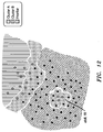
- FIG. 12 is a diagram illustrating a network according to a fourth embodiment of the invention, in which a few cells of a cluster, those cells forming a boundary region only, lie within another cluster.
- network node optimisation As an example of network node optimisation, the inventors considered cell coverage optimisation specifically in femtocell deployments, in other words where the netwrk nodes are femtocell base stations. The inventors considered cell coverage optimisation as an example because it is easy to visualise. Of course, other properties or attributes of nodes may be optimised in addition or instead.
- FIG. 1 shows three neighbouring femtocells (A,B, and C) at four sequential instances in time (steps i, ii, iii, and iv). For example, as shown in FIG.
- FemtocellA decreasing its coverage causes its neighbour FemtocellB to increase its coverage (step iii) in consequence so as to fill a coverage gap.
- FemtocellC causes FemtocellC to decrease (step iv) its coverage area.
- Such changes in coverage can lead to temporary conditions where quality of service is reduced and control signalling (as opposed to user traffic) is increased.
- coverage optimisation we again consider coverage optimisation as an example because it is easily visualised.
- DSLAM Digital Subscriber Line Access Multiplier
- boundary optimisation cell coverage areas of femtocells at the frontiers become fixed such that disruptions and perturbations in cell coverage areas of femtocells within a cluster are contained within that cluster.
- femtocell base stations (a few of which are denoted 2 for ease of understanding) are each connected via respective Digital Subscriber Line (xDSL) connections, in other words, Internet backhaul connections, to a Digital Subsciber Line Access Multiplier (DSLAM) shared with other femtocells. All the femtocells connected to the same DSLAM form a cluster.
- xDSL Digital Subscriber Line
- DSLAM Digital Subsciber Line Access Multiplier
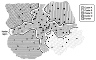
- femto in clusterA is shown as a black triangle
- a femto in clusterB is shown as a white-centred circle
- a femto in clusterC is shown as a black square
- a femto in clusterD is shown by a black circle.
- the DSLAMs are connected together in a Metropolitan Access Network (MAN) that includes a central office 4 having backbone connection 6 to the rest of the telecommunications world (not shown). Information is exchanged between DSLAMs via the MAN.
- MAN Metropolitan Access Network
- each cluster independently starts its own femto coverage area optimisation process.
- the optimisation process uses genetic programming, as is known from, for example, the paper by Ho L T W, Ashraf I, and Claussen H entitled “Evolving Femtocell Coverage Optimisation Algorithms Using Genetic Programming” in Proc. IEEE PIMRC 9, Sep. 2009, and more generally the book by John Koza “Genetic Programming: On the Programming of Computers by Means of Natural Selection, MIT Press, 1992.
- each cluster has no knowledge of its respective neighbours so a frontier between clusters is not defined, and hence can be considered as merely virtual.
- the optimisation within each cluster is aimed at maximising overall coverage within each cluster area and identifying the frontiers, as explained in relation to FIGS. 5 and 6 below.
- each femto 2 has an associated femtocell coverage area, a few of which are indicated by the reference numeral 10 for ease of understanding.
- adjacent clusters will overlap in their coverage area so as to define a respective frontier 12 .
- FIGS. 5 and 6 where optimisation of coverage areas in clusterA and ClusterB has the effect of filling the area 8 in FIG. 5 where there is no coverage, so as to give the coverage shown in FIG. 6 including defining the frontier between clusterA and clusterB.
- the frontier definition process is by feedback information from mobile user terminals.
- a mobile user terminal senses it is in the overlapping coverage area of two overlapping femtocells but those two femtocells are connected to different Digital Subscriber Line Access Multipliers (DSLAMs), in other words the two femtos are in different clusters, then the mobile user terminal informs the two femtos of this situation.
- the two femtos each forwards this information to its respective DSLAM, where the information is used to update a database table identifying femtos at the frontier.
- DSLAM Digital Subscriber Line Access Multipliers
- the DSLAM of each cluster removes the femtos that are identified as being at along frontier from the within cluster cell coverage optimisation process. In this within-cluster process, their coverage areas are then considered to be steady rather than variable. Accordingly when a change or perturbation in cell sizes propagates through a cluster, these femtos at the frontier have steady coverage areas so act to inhibit or prevent the change or perturbation moving into a neighbouring cluster.
- the cells along the frontier with a neighbouring cluster are optimised as to their cell coverage without further considering the rest of the femtos in their respective clusters. This is to provide maximum coverage in the frontier region only.
- dashed lines is shown merely to indicate the frontier region edges, such femtos between a frontier (solid line) and frontier region edge (dashed line) are considered at the respective frontier for cell coverage optimisation purposes.
- the optimisation process uses genetic programming, as is known from, for example, the paper by Ho L T W, Ashraf I, and Claussen H entitled “Evolving Femtocell Coverage Optimisation Algorithms Using Genetic Programming” in Proc. IEEE PIMRC 9, Sep. 2009, and more generally the book by John Koza “Genetic Programming: On the Programming of Computers by Means of Natural Selection, MIT Press, 1992.
- alternative methodologies to genetic programming are used, such as Reinforcement Learning and Neuro-fuzzy logic.
- two or more methodologies are used in combination.
- This optimisation process is performed by the Digital Subscriber Line Access Multiplier (DSLAM) elected to do that for each frontier.
- DSLAM Digital Subscriber Line Access Multiplier
- this process can be performed in a distributed manner by the relevant femtos.
- this optimisation process is performed by an external entity, for example a computational element.
- FIG. 8 The result of boundary optimisation is shown in FIG. 8 for comparison with FIG. 7 . It will be seen for example that coverage gaps along the frontier have been closed.
- the maximum number of femtos that may be in the cluster is known in advance. Accordingly, the maximum number of femtos in the frontier region is limited as is the computational complexity in reaching a convergent solution.
- the computational hardware for the inner and boundary optimisations may be optimised in terms of speed, power consumption, size etc for these processes at the scale of the numbers of femtos involved.
- the computational hardware is located in the DSLAMs.
- the hardware is distributed in the femtos.
- the hardware is in an external entity (e.g. a computational element).
- step a upon booting up (step a), the femto is automatically included in the inner optimisation process (step b) which deals with power hence coverage area of femtos within the cluster.
- the femto is given a status of “normal” for this purpose.
- a query is then made as to whether (step c) the femtocell is in a frontier region. This query is made upon every algorithm iteration (In an alternative embodiment, the query could be made every time frame).
- the query could be made every time frame.
- the status of the femto is changed (step e) to “frontier”.
- step h the “frontier”-status femto is still a part of the inner optimisation process (step h) its power level and hence coverage area is set (step g) for that purpose as being steady.
- step f the “frontier”-status femto is included in the boundary optimisation process (step f), which does not consider the non-frontier region femtos.
- the effect of introducing frontiers that prevent all nodes in a network from being reconfigured when a change occurs in one cluster may mean that a theoretical optimum global coverage configuration may not be achievable in consequence.
- the deviation from this ideal may be measured or evaluated and may be used as a parameter in clustering and optimisation methods.
- DSLAMs Digital Subscriber Line Access Multipliers
- An alternative is to instead do this in a distributed manner.
- Another alternative is for an external entity, for example, a computational element, to do this.
- femtos were considered as clustered by being connected to the same DSLAM.
- other groupings are possible, such as grouping femtos according to their paging area codes.
- boundary optimisation and within cluster optimisation may depend on the given scenario and constraints. For example, in some other embodiments, for example if femtos are topology-aware such that the femtos at frontiers are identified without within cluster optimisation, then boundary optimisation is performed before within cluster optimisation. In some other embodiments (not shown) for example in critical applications where femtos need setup times that are minimised, the boundary optimisation and within cluster optimisation are performed in parallel.
- clusters can slightly overlap. This may occur in, for example, in real xDSL deployments with regions served by different Digital Subscriber Line Access Multipliers (DSLAMs) somewhat overlapping.
- DSLAMs Digital Subscriber Line Access Multipliers
- the method as described in relation to FIGS. 3 to 8 applies except that a thicker frontier region results.
- some other scenarios are where some femtocell base stations belong to a first cluster, lie within a second cluster, detached from the main first cluster.
- a substantial number of femtos from clusterA lying within clusterB can be considered as an “island” having both cells in an inner region 14 and in a frontier region.
- the inner region is identified for example from information std in a topology record table in the network.
- a within-region optimisation (within-cluster type optimisation) is performed.
- a boundary optimisation is performed.
- a smaller number of femtos from clusterA lying within clusterB can be considered as an “atoll” having a frontier region 18 only.
- atoll having a frontier region 18 only.
- program storage devices e.g., digital data storage media, which are machine or computer readable and encode machine-executable or computer-executable programs of instructions, wherein said instructions perform some or all of the steps of said above-described methods.
- the program storage devices may be, e.g., digital memories, magnetic storage media such as a magnetic disks and magnetic tapes, hard drives, or optically readable digital data storage media.
- Some embodiments involve computers programmed to perform said steps of the above-described methods.
Landscapes
- Engineering & Computer Science (AREA)
- Computer Networks & Wireless Communication (AREA)
- Signal Processing (AREA)
- Mobile Radio Communication Systems (AREA)
Abstract
Description
Claims (15)
Applications Claiming Priority (4)
| Application Number | Priority Date | Filing Date | Title |
|---|---|---|---|
| EP10290033.9 | 2010-01-18 | ||
| EP10290033 | 2010-01-18 | ||
| EP10290033A EP2346209B1 (en) | 2010-01-18 | 2010-01-18 | Management of configuration changes in clustered network nodes |
| PCT/EP2010/007773 WO2011085785A1 (en) | 2010-01-18 | 2010-12-16 | Management of configuration changes in clustered network nodes |
Publications (2)
| Publication Number | Publication Date |
|---|---|
| US20130053046A1 US20130053046A1 (en) | 2013-02-28 |
| US9313675B2 true US9313675B2 (en) | 2016-04-12 |
Family
ID=42227685
Family Applications (1)
| Application Number | Title | Priority Date | Filing Date |
|---|---|---|---|
| US13/522,088 Active 2031-08-28 US9313675B2 (en) | 2010-01-18 | 2010-12-16 | Telecommunications network node configuration |
Country Status (6)
| Country | Link |
|---|---|
| US (1) | US9313675B2 (en) |
| EP (1) | EP2346209B1 (en) |
| JP (1) | JP5367183B2 (en) |
| KR (1) | KR101398408B1 (en) |
| CN (1) | CN102714605B (en) |
| WO (1) | WO2011085785A1 (en) |
Families Citing this family (4)
| Publication number | Priority date | Publication date | Assignee | Title |
|---|---|---|---|---|
| CN104581748B (en) * | 2013-10-09 | 2018-10-12 | 中国移动通信集团设计院有限公司 | A kind of method and apparatus identifying scene within a wireless communication network |
| JP6581529B2 (en) * | 2016-03-11 | 2019-09-25 | 株式会社Nttドコモ | Management device |
| CN106370444B (en) * | 2016-08-16 | 2017-07-07 | 深圳高速工程检测有限公司 | Diagnosing structural damage method and structure based on information fusion damages diagnostic system |
| CN110519821B (en) * | 2019-09-09 | 2023-10-10 | 贵州电网有限责任公司 | Method for selecting wireless sensor network cluster head of intelligent power distribution network |
Citations (9)
| Publication number | Priority date | Publication date | Assignee | Title |
|---|---|---|---|---|
| WO2002080458A1 (en) | 2001-03-30 | 2002-10-10 | Nokia Corporation | Method for configuring a network by defining clusters |
| US20040229621A1 (en) * | 2003-05-16 | 2004-11-18 | International Business Machines Corporation | Method and apparatus for load sharing in wireless access networks based on dynamic transmission power adjustment of access points |
| US20050289228A1 (en) | 2004-06-25 | 2005-12-29 | Nokia Inc. | System and method for managing a change to a cluster configuration |
| EP1830515A1 (en) | 2004-12-06 | 2007-09-05 | Huawei Technologies Co., Ltd. | A method for transferring the network management configuration information between the element management systems |
| EP1848159A1 (en) | 2005-02-07 | 2007-10-24 | Huawei Technologies Co., Ltd. | A method for the local sub-network discovering the destination border object of the corresponding sub-network and the device thereof |
| US20080064361A1 (en) * | 2006-09-08 | 2008-03-13 | Telefonaktiebolaget Lm Ericsson (Publ) | Non-homogenous telecommunications base stations |
| US20080096556A1 (en) * | 2004-10-27 | 2008-04-24 | Fujitsu Limited | Wireless base station and mobile station |
| US20090131049A1 (en) * | 2007-06-21 | 2009-05-21 | Airwalk Communications, Inc. | System, method, and computer-readable medium for user equipment handoff within an ip-femtocell network |
| US20110275397A1 (en) * | 2009-01-23 | 2011-11-10 | Telefonaktiebolaget Lm Ericsson (Publ) | Uplink Reference Signal Allocation and Assignment for Cell Clusters |
Family Cites Families (2)
| Publication number | Priority date | Publication date | Assignee | Title |
|---|---|---|---|---|
| JPH06268574A (en) * | 1993-03-11 | 1994-09-22 | Hitachi Ltd | Cellular mobile communications system |
| FR2828622B1 (en) * | 2001-08-10 | 2003-12-12 | Radiotelephone Sfr | PLANNING LOCATION AREAS |
-
2010
- 2010-01-18 EP EP10290033A patent/EP2346209B1/en active Active
- 2010-12-16 WO PCT/EP2010/007773 patent/WO2011085785A1/en not_active Ceased
- 2010-12-16 CN CN201080061808.0A patent/CN102714605B/en active Active
- 2010-12-16 JP JP2012549262A patent/JP5367183B2/en not_active Expired - Fee Related
- 2010-12-16 KR KR1020127021422A patent/KR101398408B1/en not_active Expired - Fee Related
- 2010-12-16 US US13/522,088 patent/US9313675B2/en active Active
Patent Citations (9)
| Publication number | Priority date | Publication date | Assignee | Title |
|---|---|---|---|---|
| WO2002080458A1 (en) | 2001-03-30 | 2002-10-10 | Nokia Corporation | Method for configuring a network by defining clusters |
| US20040229621A1 (en) * | 2003-05-16 | 2004-11-18 | International Business Machines Corporation | Method and apparatus for load sharing in wireless access networks based on dynamic transmission power adjustment of access points |
| US20050289228A1 (en) | 2004-06-25 | 2005-12-29 | Nokia Inc. | System and method for managing a change to a cluster configuration |
| US20080096556A1 (en) * | 2004-10-27 | 2008-04-24 | Fujitsu Limited | Wireless base station and mobile station |
| EP1830515A1 (en) | 2004-12-06 | 2007-09-05 | Huawei Technologies Co., Ltd. | A method for transferring the network management configuration information between the element management systems |
| EP1848159A1 (en) | 2005-02-07 | 2007-10-24 | Huawei Technologies Co., Ltd. | A method for the local sub-network discovering the destination border object of the corresponding sub-network and the device thereof |
| US20080064361A1 (en) * | 2006-09-08 | 2008-03-13 | Telefonaktiebolaget Lm Ericsson (Publ) | Non-homogenous telecommunications base stations |
| US20090131049A1 (en) * | 2007-06-21 | 2009-05-21 | Airwalk Communications, Inc. | System, method, and computer-readable medium for user equipment handoff within an ip-femtocell network |
| US20110275397A1 (en) * | 2009-01-23 | 2011-11-10 | Telefonaktiebolaget Lm Ericsson (Publ) | Uplink Reference Signal Allocation and Assignment for Cell Clusters |
Non-Patent Citations (1)
| Title |
|---|
| International Search Report for PCT/EP2010/007773 dated Apr. 15, 2011. |
Also Published As
| Publication number | Publication date |
|---|---|
| JP2013517721A (en) | 2013-05-16 |
| EP2346209A1 (en) | 2011-07-20 |
| CN102714605B (en) | 2014-12-03 |
| JP5367183B2 (en) | 2013-12-11 |
| CN102714605A (en) | 2012-10-03 |
| US20130053046A1 (en) | 2013-02-28 |
| KR101398408B1 (en) | 2014-05-27 |
| WO2011085785A1 (en) | 2011-07-21 |
| EP2346209B1 (en) | 2013-03-20 |
| KR20120109632A (en) | 2012-10-08 |
Similar Documents
| Publication | Publication Date | Title |
|---|---|---|
| Aliu et al. | A survey of self organisation in future cellular networks | |
| Sun et al. | An intelligent SDN framework for 5G heterogeneous networks | |
| US11844143B2 (en) | Dynamic cell boundary roaming management using client feedback | |
| US20220311671A1 (en) | Network intent synthesis | |
| Qiu et al. | Demand‐aware resource allocation for ultra‐dense small cell networks: an interference‐separation clustering‐based solution | |
| Kim et al. | Alpha-optimal user association and cell load balancing in wireless networks | |
| US9313675B2 (en) | Telecommunications network node configuration | |
| Arslan et al. | SDoff: A software-defined offloading controller for heterogeneous networks | |
| Syed-Yusof et al. | Software-defined networking (SDN) and 5G network: The role of controller placement for scalable control plane | |
| Yang et al. | Energy saving in cellular networks by dynamic RS–BS association and BS switching | |
| Shahid et al. | A docitive Q‐learning approach towards joint resource allocation and power control in self‐organised femtocell networks | |
| CN109863820A (en) | System and method for scalable radio network slicing | |
| Du et al. | Data-driven deployment and cooperative self-organization in ultra-dense small cell networks | |
| Banerjee et al. | On the implementation of cognitive autonomous networks | |
| CN116232923A (en) | Model training method and device, network traffic prediction method and device | |
| US9319892B2 (en) | Dynamic management of small cells for optimizing the energy consumption of a network | |
| WO2015036085A1 (en) | Energy saving | |
| Bartoli et al. | AI based network and radio resource management in 5G HetNets | |
| Daher et al. | Softwarized and distributed learning for SON management systems | |
| EP2779756A1 (en) | Control of user equipment to base station association to optimise network capacity utilisation | |
| Mwanje et al. | Fluid capacity for energy saving management in multi-layer ultra-dense 4G/5G cellular networks | |
| Sedlacek et al. | Analysis of neighbourhood relations for femtocell networks | |
| Cabuk et al. | Analysis of movement-based connectivity restoration problem in wireless ad-hoc and sensor networks | |
| Valente Klaine | Self-organization for 5g and beyond mobile networks using reinforcement learning | |
| EP4555764A1 (en) | Method and system to coordinate agents and avoid conflicts |
Legal Events
| Date | Code | Title | Description |
|---|---|---|---|
| AS | Assignment |
Owner name: ALCATEL LUCENT, FRANCE Free format text: ASSIGNMENT OF ASSIGNORS INTEREST;ASSIGNORS:CHERUBINI, DAVIDE;ROUZBEH, RAZAVI;HO, LESTER TSE WEE;AND OTHERS;SIGNING DATES FROM 20120905 TO 20120906;REEL/FRAME:029142/0219 |
|
| AS | Assignment |
Owner name: CREDIT SUISSE AG, NEW YORK Free format text: SECURITY AGREEMENT;ASSIGNOR:LUCENT, ALCATEL;REEL/FRAME:029821/0001 Effective date: 20130130 Owner name: CREDIT SUISSE AG, NEW YORK Free format text: SECURITY AGREEMENT;ASSIGNOR:ALCATEL LUCENT;REEL/FRAME:029821/0001 Effective date: 20130130 |
|
| AS | Assignment |
Owner name: ALCATEL LUCENT, FRANCE Free format text: RELEASE BY SECURED PARTY;ASSIGNOR:CREDIT SUISSE AG;REEL/FRAME:033868/0555 Effective date: 20140819 |
|
| STCF | Information on status: patent grant |
Free format text: PATENTED CASE |
|
| MAFP | Maintenance fee payment |
Free format text: PAYMENT OF MAINTENANCE FEE, 4TH YEAR, LARGE ENTITY (ORIGINAL EVENT CODE: M1551); ENTITY STATUS OF PATENT OWNER: LARGE ENTITY Year of fee payment: 4 |
|
| MAFP | Maintenance fee payment |
Free format text: PAYMENT OF MAINTENANCE FEE, 8TH YEAR, LARGE ENTITY (ORIGINAL EVENT CODE: M1552); ENTITY STATUS OF PATENT OWNER: LARGE ENTITY Year of fee payment: 8 |