US9312075B1 - High voltage tantalum anode and method of manufacture - Google Patents
High voltage tantalum anode and method of manufacture Download PDFInfo
- Publication number
- US9312075B1 US9312075B1 US14/479,689 US201414479689A US9312075B1 US 9312075 B1 US9312075 B1 US 9312075B1 US 201414479689 A US201414479689 A US 201414479689A US 9312075 B1 US9312075 B1 US 9312075B1
- Authority
- US
- United States
- Prior art keywords
- tantalum
- pellet
- powder
- agglomerated
- ranging
- Prior art date
- Legal status (The legal status is an assumption and is not a legal conclusion. Google has not performed a legal analysis and makes no representation as to the accuracy of the status listed.)
- Ceased
Links
Images


Classifications
-
- H—ELECTRICITY
- H01—ELECTRIC ELEMENTS
- H01G—CAPACITORS; CAPACITORS, RECTIFIERS, DETECTORS, SWITCHING DEVICES, LIGHT-SENSITIVE OR TEMPERATURE-SENSITIVE DEVICES OF THE ELECTROLYTIC TYPE
- H01G9/00—Electrolytic capacitors, rectifiers, detectors, switching devices, light-sensitive or temperature-sensitive devices; Processes of their manufacture
- H01G9/004—Details
- H01G9/04—Electrodes or formation of dielectric layers thereon
- H01G9/048—Electrodes or formation of dielectric layers thereon characterised by their structure
- H01G9/052—Sintered electrodes
- H01G9/0525—Powder therefor
-
- B—PERFORMING OPERATIONS; TRANSPORTING
- B22—CASTING; POWDER METALLURGY
- B22F—WORKING METALLIC POWDER; MANUFACTURE OF ARTICLES FROM METALLIC POWDER; MAKING METALLIC POWDER; APPARATUS OR DEVICES SPECIALLY ADAPTED FOR METALLIC POWDER
- B22F1/00—Metallic powder; Treatment of metallic powder, e.g. to facilitate working or to improve properties
- B22F1/14—Treatment of metallic powder
- B22F1/148—Agglomerating
-
- B—PERFORMING OPERATIONS; TRANSPORTING
- B22—CASTING; POWDER METALLURGY
- B22F—WORKING METALLIC POWDER; MANUFACTURE OF ARTICLES FROM METALLIC POWDER; MAKING METALLIC POWDER; APPARATUS OR DEVICES SPECIALLY ADAPTED FOR METALLIC POWDER
- B22F3/00—Manufacture of workpieces or articles from metallic powder characterised by the manner of compacting or sintering; Apparatus specially adapted therefor ; Presses and furnaces
- B22F3/24—After-treatment of workpieces or articles
-
- H—ELECTRICITY
- H01—ELECTRIC ELEMENTS
- H01G—CAPACITORS; CAPACITORS, RECTIFIERS, DETECTORS, SWITCHING DEVICES, LIGHT-SENSITIVE OR TEMPERATURE-SENSITIVE DEVICES OF THE ELECTROLYTIC TYPE
- H01G9/00—Electrolytic capacitors, rectifiers, detectors, switching devices, light-sensitive or temperature-sensitive devices; Processes of their manufacture
- H01G9/0029—Processes of manufacture
- H01G9/0032—Processes of manufacture formation of the dielectric layer
-
- H—ELECTRICITY
- H01—ELECTRIC ELEMENTS
- H01G—CAPACITORS; CAPACITORS, RECTIFIERS, DETECTORS, SWITCHING DEVICES, LIGHT-SENSITIVE OR TEMPERATURE-SENSITIVE DEVICES OF THE ELECTROLYTIC TYPE
- H01G9/00—Electrolytic capacitors, rectifiers, detectors, switching devices, light-sensitive or temperature-sensitive devices; Processes of their manufacture
- H01G9/004—Details
- H01G9/02—Diaphragms; Separators
-
- H—ELECTRICITY
- H01—ELECTRIC ELEMENTS
- H01G—CAPACITORS; CAPACITORS, RECTIFIERS, DETECTORS, SWITCHING DEVICES, LIGHT-SENSITIVE OR TEMPERATURE-SENSITIVE DEVICES OF THE ELECTROLYTIC TYPE
- H01G9/00—Electrolytic capacitors, rectifiers, detectors, switching devices, light-sensitive or temperature-sensitive devices; Processes of their manufacture
- H01G9/004—Details
- H01G9/04—Electrodes or formation of dielectric layers thereon
- H01G9/048—Electrodes or formation of dielectric layers thereon characterised by their structure
- H01G9/052—Sintered electrodes
-
- H—ELECTRICITY
- H01—ELECTRIC ELEMENTS
- H01G—CAPACITORS; CAPACITORS, RECTIFIERS, DETECTORS, SWITCHING DEVICES, LIGHT-SENSITIVE OR TEMPERATURE-SENSITIVE DEVICES OF THE ELECTROLYTIC TYPE
- H01G9/00—Electrolytic capacitors, rectifiers, detectors, switching devices, light-sensitive or temperature-sensitive devices; Processes of their manufacture
- H01G9/004—Details
- H01G9/08—Housing; Encapsulation
- H01G9/10—Sealing, e.g. of lead-in wires
-
- H—ELECTRICITY
- H01—ELECTRIC ELEMENTS
- H01G—CAPACITORS; CAPACITORS, RECTIFIERS, DETECTORS, SWITCHING DEVICES, LIGHT-SENSITIVE OR TEMPERATURE-SENSITIVE DEVICES OF THE ELECTROLYTIC TYPE
- H01G9/00—Electrolytic capacitors, rectifiers, detectors, switching devices, light-sensitive or temperature-sensitive devices; Processes of their manufacture
- H01G9/145—Liquid electrolytic capacitors
-
- B—PERFORMING OPERATIONS; TRANSPORTING
- B22—CASTING; POWDER METALLURGY
- B22F—WORKING METALLIC POWDER; MANUFACTURE OF ARTICLES FROM METALLIC POWDER; MAKING METALLIC POWDER; APPARATUS OR DEVICES SPECIALLY ADAPTED FOR METALLIC POWDER
- B22F3/00—Manufacture of workpieces or articles from metallic powder characterised by the manner of compacting or sintering; Apparatus specially adapted therefor ; Presses and furnaces
- B22F3/24—After-treatment of workpieces or articles
- B22F2003/241—Chemical after-treatment on the surface
- B22F2003/242—Coating
-
- B—PERFORMING OPERATIONS; TRANSPORTING
- B22—CASTING; POWDER METALLURGY
- B22F—WORKING METALLIC POWDER; MANUFACTURE OF ARTICLES FROM METALLIC POWDER; MAKING METALLIC POWDER; APPARATUS OR DEVICES SPECIALLY ADAPTED FOR METALLIC POWDER
- B22F2998/00—Supplementary information concerning processes or compositions relating to powder metallurgy
- B22F2998/10—Processes characterised by the sequence of their steps
-
- B—PERFORMING OPERATIONS; TRANSPORTING
- B22—CASTING; POWDER METALLURGY
- B22F—WORKING METALLIC POWDER; MANUFACTURE OF ARTICLES FROM METALLIC POWDER; MAKING METALLIC POWDER; APPARATUS OR DEVICES SPECIALLY ADAPTED FOR METALLIC POWDER
- B22F2999/00—Aspects linked to processes or compositions used in powder metallurgy
-
- B—PERFORMING OPERATIONS; TRANSPORTING
- B22—CASTING; POWDER METALLURGY
- B22F—WORKING METALLIC POWDER; MANUFACTURE OF ARTICLES FROM METALLIC POWDER; MAKING METALLIC POWDER; APPARATUS OR DEVICES SPECIALLY ADAPTED FOR METALLIC POWDER
- B22F5/00—Manufacture of workpieces or articles from metallic powder characterised by the special shape of the product
Definitions
- the present invention generally relates to a valve metal anode for a capacitor, and more particularly, to an electrolytic capacitor comprising an anode formed from a pressed pellet of tantalum fibers.
- the tantalum fiber pellet is sintered and then anodized into a high voltage anode at formation voltages up to 550V.
- tantalum capacitor Development of powders suitable for making a tantalum capacitor has been a focus of both capacitor producers and tantalum processors. Historically, the intent has been to delineate requirements for tantalum powder that will result in capacitors having reliable performance, particularly in demanding high voltage applications such as cardiac defibrillation. It is understood that demanding applications, such as cardiac defibrillation, require tantalum powders having suitable surface area, high purity, uniform feature size, optimized shrinkage, favorable flowability and pressability, and green pellet strength.
- Wet tantalum capacitors have been used in implantable cardiac defibrillators as the output energy storage capacitor for delivering the therapeutic electrical shock to the heart to stop a defibrillation event. These shocks are generally delivered at voltages ranging from approximately 650 volts to 950 volts. To achieve therapy delivery at such high voltage levels, between three and four tantalum capacitors are typically used in the output stage of the defibrillator.
- one purpose of this invention is to develop a manufacturing process for tantalum anodes that are suitable for building an electrolytic capacitor for incorporation into a cardiac defibrillator.
- the manufacturing processes include pressing, sintering and forming steps. It is also the purpose of this invention to fabricate a tantalum anode that is capable of being formed at higher voltages than is currently known in the prior art.
- An anode for high voltage applications such as described within must also have a pore structure and internal surface area that allows for low ESR and high capacitance.
- ESR is related to energy loss. It is also known that for a capacitor, energy loss during charging and discharging impacts capacitor efficiency. Hence, a lower ESR of an anode made in accordance with the present invention improves the efficiency of the capacitor. This is of significance in cardiac defibrillation as discharge of the capacitor delivers the energy needed to return the heart to normal rhythm.
- the improved efficiency achieved by the present invention enables delivery of energy and higher voltages, and allows for smaller batteries to be used in implantable defibrillators due to less energy being required to charge the capacitors. Improvement in the capacitance per unit volume of an anode of the present invention allows more charge to be stored per unit volume, resulting in a capacitor that stores more energy per unit volume.
- tantalum powders When tantalum powders are formed into a porous anode body and then sintered for use in an electrolytic capacitor, it is known that the resultant anode capacitance is proportional to the specific surface area of the sintered porous body. The greater the specific surface area after sintering, the greater the anode capacitance ( ⁇ FV/g) is. Since the anode capacitance ( ⁇ FV/g) of a tantalum pellet is a function of the specific surface area of the sintered powder, one way to achieve a greater net surface area is by increasing the quantity (grams) of powder per pellet. However, with this approach cost and size increase considerably. Consequently, cost and size considerations dictate that tantalum powder development focus on means to increase the specific surface area of the powder itself.
- Prior art methods for increasing the specific surface area of tantalum powder include flattening the powder particles into a flake shape or spherical granulation to produce ovular particle shapes.
- U.S. Pat. No. 4,940,490 to Fife et al. U.S. Pat. No. 5,211,741 to Fife and U.S. Pat. No. 5,580,367 to Fife disclose flaked tantalum powders and methods for making the flaked powders.
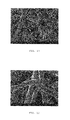
- FIG. 1 is an SEM photograph at 5,000 ⁇ showing flake tantalum particles according to the prior art.
- FIG. 2 is an SEM photograph at 1,000 ⁇ showing EB melt tantalum particles according to the prior art.
- FIG. 3 is an SEM photograph at 5,000 ⁇ showing a sodium reduced NH-175 tantalum powder agglomerate according to the prior art.
- Purity of the powder is another important consideration. Metallic and non-metallic contamination tends to degrade the dielectric oxide film in tantalum capacitors. While high sintering temperatures serve to remove some volatile contaminants, not all may be removed sufficiently, resulting in sites having high DC leakage. High DC leakage is known to contribute to premature electrical failures, particularly in high voltage applications. Further, high sintering temperatures tend to shrink the porous anode body, thereby reducing its net specific surface area and thus the capacitance of the resulting capacitor. Therefore, minimizing loss of specific surface area under sintering conditions, i.e., shrinkage, is necessary in order to produce high ⁇ FV/g tantalum capacitors.
- Flowability of tantalum powder and green strength are also important characteristics for a capacitor producer. Not only does flowability provide for efficient pellet production, it provides for high volume, automated pellet production. Flowability of agglomerated tantalum powder is even more essential to production efficiency and proper operation of automatic pellet presses. Sufficient green strength permits handling and transport of a pressed product, e.g., pellet, without excessive breakage or pellet damage (detectable and undetectable) that could affect production reject rates and finished product performance.
- a tantalum fiber of a strictly controlled diameter such that sufficient metal remains after formation to provide a conductive matrix behind the dielectric oxide. Because of the tightly controlled fiber diameter according to the present invention, fiber diameter can be minimized to a greater extent than with other prior art powder types. By minimizing fiber diameter while ensuring that tantalum is not totally consumed during formation, the dielectric surface area can be maximized without isolating dielectric area due to loss of tantalum substrate.
- a tantalum anode according to the present invention is distinguishable from the prior art. Regardless whether the tantalum is of a flake or spherical shape manufactured by the beam melt (QR-3 powder) or sodium reduction processes (NH-175 powder), the present invention uniquely discloses the pressing and sintering of an agglomerate of tantalum fibers having a tightly controlled aspect ratio. The result is an electrode pellet having a dual morphology and that is capable of being anodized into a capacitor anode at formation voltages up to 550V.
- anodes having high per unit surface area must be fabricated.
- High surface area anodes must also have pore structures that allow for good internal cooling during anode formation, and have lower ESR both during formation and subsequently while in use in the finished capacitor.
- the use of tantalum anodes made from tantalum fibers according to the present invention improves on these issues.
- the diameter of the tantalum fibers used to generate the finished pellet is tightly controlled.
- the tantalum fibers are divided into desired lengths (up to 50 microns) to form a randomly oriented, porous powder (primary powder).
- the primary powder is subsequently subjected to an agglomeration process to thereby form an agglomerated powder of the tantalum fibers.
- An exemplary agglomeration process is described in U.S. Pat. No. 5,217,526 to Fife wherein tantalum fibers of the primary powder are heat treated at 1,000° C. for 30 minutes.
- the random agglomerate structure is stabilized by fiber-to-fiber bonding (sintering).
- the resulting agglomerated powder has very narrow particle and pore size distribution.
- the agglomerated powder can be pressed into a pellet of a desired shape comprising the tantalum fibers of the tightly controlled diameter used to make the primary powder, but with a pellet structure provided with larger sized pores provided by the agglomeration of the primary powder.
- This so called “dual morphology” or dual porosity pellet structure allows for better electrolyte penetration. Better electrolyte penetration aids in both cooling of the pellet during formation as well as lowering the ESR of the pellet when used as an anode in a capacitor.
- FIG. 1 is an SEM photograph at 5,000 ⁇ showing flake tantalum particles according to the prior art.
- FIG. 2 is an SEM photograph at 1,000 ⁇ showing EB melt tantalum particles according to the prior art.
- FIG. 3 is an SEM photograph at 5.000 ⁇ showing a sodium reduced tantalum powder agglomerate according to the prior art.
- FIG. 4A is a transverse cross section of a primary billet 10 used in the production of tantalum fibers.
- FIG. 4B is a cutaway view of the primary billet 10 shown in FIG. 4A revealing the longitudinal disposition of the billet components.
- FIG. 5 is a schematic depiction of the transverse cross section of the secondary billet 22 used to make tantalum fibers.
- FIG. 6 is a schematic depiction showing a cylindrical body containing a plurality of tantalum fibers.
- FIGS. 7 and 8 are SEM photographs at 70 ⁇ and 500 ⁇ , respectively, showing the present tantalum powder as coarse agglomerate with high surface area and small pore structure.
- FIGS. 9 and 10 are SEM photographs at 1,000 ⁇ and 2,000 ⁇ , respectively, showing the present tantalum powder having a relatively uniform fiber diameter.
- FIG. 11 is an SEM photograph at 4,000 ⁇ showing the present tantalum powder having good random 3-D fiber orientation.
- FIG. 12 is an SEM photograph at 10,000 ⁇ showing the present tantalum powder having good uniform inter-particle spacing.
- FIG. 13 is an SEM photograph at 25 ⁇ showing the pore structure of a pellet pressed from a tantalum powder according to the present invention.
- FIG. 14 is an SEM photograph at 200 ⁇ showing the pore structure of a pellet pressed from a tantalum powder according to the present invention.
- FIG. 15 is a perspective view of a capacitor 100 according to the present invention.
- FIG. 16 is a perspective view of a dual anode/cathode assembly for the capacitor 100 shown in FIG. 15 .
- a fiber is a very fine thread or threadlike tantalum filament of indefinite length.
- a primary powder is a mass of loose tantalum fibers.
- An agglomerated powder is a mass of primary powders which have been bonded together through an agglomeration process by heating the primary powder under chemically non-reactive conditions to a temperature sufficient to form stabilized fiber-to-fiber bonding.
- the resulting tantalum bodies consist essentially of short relatively uniform diameter tantalum fibers, bonded and randomly oriented in a substantially non-aligned, porous array.
- the process for manufacturing tantalum fibers for fabricating a tantalum anode that are useful for building capacitors begins as a primary billet 10 comprising tantalum rods 12 that have been inserted into holes 14 drilled longitudinally into a copper matrix 16 .
- copper separates the tantalum rods 12 from each other.
- the rods 12 run longitudinally through the body of the billet and are substantially uniform in diameter and aligned in parallel.
- a copper nose 18 and tail 20 are welded onto the primary billet 10 , and the billet is then evacuated and sealed.
- the primary billet. 10 may optionally be hot or cold isostatically pressed in order to collapse any void space, thereby promoting filament uniformity.
- the primary billet 10 containing the tantalum rods 12 in a copper matrix 16 is extruded at elevated temperature at a diameter reduction ratio of approximately 6:1.
- the resulting rod is cropped and then drawn down to restack diameter.
- Annealing may optionally be performed during drawing should the wire become too stiff or breakage occurs.
- Annealing temperatures for tantalum are typically in the range of 900° C.
- the composite wire is cut into lengths for assembly into a secondary billet 22 ( FIG. 5 ).
- the sub-elements 24 made from the primary billet are stacked together with copper rods.
- the copper rods are used to form a copper core 26 and an outer annulus 28 .
- the core 26 and the outer annulus 28 make leaching of the final composite less difficult.
- An outer tantalum sheet 30 covers the assembly of sub-elements and copper rods.
- the sheet 30 is the same length as the rods and it completely surrounds the filament array. Outside the cylinder of tantalum sheet is an outer copper can 32 .
- the secondary billet 22 is assembled, a nose and tail (not shown) are welded into place, and the billet is evacuated and sealed.
- the sealed billet is optionally prepared for extrusion by hot or cold isostatic pressing in order to collapse any void space within the billet and to promote filament uniformity. After isostatic pressing, the secondary billet is machined to fit the extrusion liner. The billet is then extruded at elevated temperature at a diameter reduction ratio of 6:1.
- the extruded rod is cropped, and the rod is then drawn to a diameter where the tantalum filament diameter is 5 microns or less. Again, annealing steps may be employed if necessary. At final size, the composite tantalum wire is cut into short lengths as required.
- the cut sections are immersed in a solution of nitric acid and water, and for a period of time sufficient for the acid to fully leach out the copper core 26 and outer annulus 28 , leaving copper tantalum filaments and the tantalum sheath 32 behind. Since the tantalum filaments are comparatively tightly spaced, the copper core 26 and annulus 28 etch away much more rapidly than the copper separating the filaments. As a result, the acid eventually surrounds the annulus of tantalum filaments, and then attacks the filament matrix from all directions, rather than just from the ends of the cut sections.
- the total leaching time depend primarily upon the composite wire diameter and length, with smaller diameters and greater lengths requiring longer times.
- tantalum filaments ⁇ 5 micron diameter
- the tube 36 is removed, leaving the tantalum filaments 34 behind.
- the tantalum fibers are of an optimum diameter range of 0.5 ⁇ m to 2.5 ⁇ m. That the tantalum filaments are of a strictly controlled diameter range is important for fabrication of an anode according to the present invention. Not only must the tantalum filaments be of a prescribed diameter, the above preparation process provides filaments of a narrow length range and high purity substantially free of copper.
- FIGS. 7 to 12 are SEM photographs at various magnifications showing tantalum fibers according to the present invention.
- the thusly produced tantalum fibers allow for the generation of anodes having a dual morphology.
- This dual morphology provides a higher surface area material compared to prior art powders.
- the term “dual morphology” means there are two pore structures within the pressed tantalum anode pellet.
- an agglomerated powder is formed by subjecting the primary powder to an agglomeration process.
- the tantalum fibers of the primary powder are heat treated at 1,000° C. for 30 minutes. This serves to stabilize the agglomerate structure through fiber-to-fiber bonding (sintering).
- exemplary agglomerating processes are described U.S. Pat. No. 4,017,302 to Bates et al. and U.S. Pat. No. 5,217,526 to Fife.
- agglomeration serves to bond the primary powders together into bodies consisting essentially of the short (5 ⁇ m to 50 ⁇ m) tantalum fibers, bonded and randomly oriented in a substantially non-aligned, porous array.
- the tight diameter distribution of the tantalum fibers in the agglomerated powder provides a relatively high surface area that is optimally suited to provide high capacitance per unit volume of a pressed pellet.
- the relatively small pores in the primary powder cause higher ESR than is desirable.
- the agglomerated powder compensates for this by providing more open pore structure than in the primary powder when used to manufacture an anode pellet.
- the dual morphology or dual porosity is the result of the porosity between the individual tantalum fibers making up the agglomerate powder and the larger secondary porosity formed between the agglomerated powder in the body of the anode.
- a diameter is defined as a straight line passing from side to side of a tantalum fiber, through its center.
- the tantalum agglomerate of a pore size from about 2 ⁇ m to about 3 ⁇ m comprising a random distribution of fibers of a diameter of from about 0.5 ⁇ m to about 2.5 ⁇ m and of a length of from about 5 ⁇ m to about 50 ⁇ m is pressed into a pellet of a desired shape.
- the pellet contains thousands of the tantalum agglomerates (a plurality).
- the pressed anode pellet has a relatively larger pore structure with lower resistance pathways within. Moreover, this open, lower resistance structure allows for better cooling of the anode pellet during the anode formation process avoiding the issues associated with prior art tantalum anode formation.
- a “pellet”, as the term is used herein, is a porous mass, body or structure comprised of agglomerated tantalum powder having the size and shape characteristics set forth in Table 1. Green strength is a measure of a pellet's mechanical strength prior to sintering. The term “pressability” describes the ability of a tantalum powder to be pressed into a pellet. Tantalum powder that can be formed into pellets that retain their shape with sufficient green strength to withstand ordinary processing and manufacturing conditions without significant breakage have good pressability.
- FIGS. 13 and 14 are photographs showing that the present uniformly-shaped tantalum fibers of the primary and agglomerated powders are suitable for forming pellet structures having relatively low compaction densities.
- the tantalum fibers deform under smaller forces and interlock with adjacent fibers to provide pellets with improved green strength.
- the high green strength also has an added benefit of permitting an agglomerate with little to no fines ( ⁇ 200 mesh) material.
- fine material often represents 50% or more of the overall powder volume. In those instances, the fine powder particulate fills the spaces between the pores and serve to densify the anode structure.
- the fibrous powder allows for an agglomerate particle having a narrow size distribution with few to none little fines that when pressed under relatively low force and then sintered, provides an open network of pores throughout the anode.
- the green tantalum structure is sintered by heating to form a coherent body.
- Sintering is a high temperature process by which two fibers touching each other at a point contact coalesce or are fused together.
- neck growth at the point contact grows to create a new grain boundary. With sufficient time, the contacting surfaces will eventually coalesce into a single large contact or contact neck.
- An exemplary sintering protocol is described in U.S. Pat. No. 6,965,510 to Liu at al, which is assigned to the assignee of the present invention and incorporated herein by reference.
- the '510 Liu et al. patent describes sintering a pressed valve metal pellet at a relatively high temperature, but for a relatively short time.
- anodizing electrolyte is described in U.S. Pat. No. 6,231,993 to Stephenson et al., which is assigned to the assignee of the present invention and incorporated herein by reference.
- An exemplary anodizing electrolyte useful with the formation protocols described in the '993 patent consists of, by volume: about 55% ethylene glycol, about 44.9% to about 43.5% deionized water and about 0.1% to about 1.5% H 3 PO 4 .
- Such an electrolyte has a conductivity of about 2,500 ⁇ S to about 2,600 ⁇ S at 40° C.
- the conductivity of the formation electrolyte can be increased to thereby reduce heat generation inside the anode pellet by using an aqueous electrolyte of H 3 PO 4 having a conductivity up to about 20,000 ⁇ S 40° C.
- U.S. Pat. No. 7,727,372 to Liu et al describes subjecting the tantalum body to a current that decreases over time, a formation voltage that increases over time to a level below the voltage from the power supply and a power level that is self-adjusted to a level that decreases excessive heating in the structure.
- a preferred formation voltage range is at least 200 V up to 550V.
- a more preferred range is from 235 V to 480 V.
- a most preferred formation voltage range is at least 300 V-up to 550 V.
- a unimodal agglomerated powder with limited particle size distribution has multiple advantages in the formation of a high voltage tantalum anode.
- a limited particle distribution provides interstitial gaps between the particles that promotes electrolyte flow and cooling of the anode during formation steps. Maintaining a low internal anode temperature during formation is critical for inhibiting growth of crystalline tantalum oxide.
- a highly porous structure allows for increased formation currents and rates, which increases production throughput and lessens the entrapment of undesirable electrolyte constituents.
- the porous anode network improves conductivity within the final assembled wet capacitor. The resistance (ESR) within the capacitor is reduced by the low anode density and open pores. This lower resistance results in higher efficiencies.
- Table 4 below demonstrates the difference in performance properties of anodes from the prior art QR-3 tantalum powder in comparison to tantalum fibers according to the present invention.
- the capacitor 100 comprises at least two anodes of an anode active material and a cathode of a cathode active material housed inside a hermetically sealed casing 102 .
- the capacitor electrodes are operatively associated with each other by a working electrolyte (not shown) contained inside the casing.
- the casing 102 comprises first and second metal casing members 104 and 106 .
- the metal casing portions 104 , 106 are preferably selected from the group consisting of tantalum, titanium, nickel, molybdenum, niobium, cobalt, stainless steel, tungsten, platinum, palladium, gold, silver, copper, chromium, vanadium, aluminum, zirconium, hafnium, zinc, iron, and mixtures and alloys thereof.
- the casing portions 104 , 106 have a thickness of about 0.001 to about 0.015 inches.
- First casing member 104 is of a drawn metal structure comprising a first face wall 108 joined to a surrounding side wall 110 extending to an edge 112 . Additionally, casing portion 104 can be of a machined construction or be formed by a metal injection molding process. Second casing member 106 is in the shape of a plate and comprises a second face wall 114 having a surrounding edge 116 . The casing members 104 and 106 are hermetically sealed together by welding the overlapping edges 112 and 116 where they contact each other.
- the weld 118 is provided by any conventional means; however, a preferred method is by laser welding.
- a feedthrough 120 electrically insulates an anode terminal wire 122 from the casing 12 .
- the terminal wire 122 extends from within the casing 102 to the outside thereof.
- the location of a hole 124 in the surrounding side wall 110 of the casing member 104 into which the feedthrough 120 is mounted is preferably offset towards the front edge 112 or towards the face wall 108 in order to align with an embedded wire of one of the anodes, as will be described subsequently.
- Feedthrough 120 is a glass to metal seal (GTMS) comprising a ferrule 126 defining an internal cylindrical through bore or passage of constant inside diameter.
- GTMS glass to metal seal
- An insulative glass 128 provides a hermetic seal between the bore of the ferrule 126 and the anode terminal wire 122 passing therethrough.
- the terminal wire 122 has a J-shaped interior portion 130 for connection to one or more anode wires within casing 102 .
- the glass 128 is, for example, ELAN® type 88 or MANSOLTM type 88.
- Capacitor 100 further comprises an anode assembly two or more anodes made as previously described and connected to the terminal wire 122 of feedthrough 120 within the casing 102 .
- the anode assembly includes a first anode pellet 132 and a second anode pellet 134 .
- the first anode pellet 132 comprises an inner major face wall 136 and an outer major face wall 138 , both extending to a surrounding edge 140 .
- the second anode pellet 134 comprises an inner major face wall 142 and an outer major face wall 144 , both extending to a surrounding edge 146 .
- An anode wire 148 that is partially embedded in the first anode pellet 132 has a distal end 148 A that is electrically connected to the J-shaped interior portion 130 of the terminal wire 122 .
- the anode wire 148 is preferably of tantalum.
- the tantalum anode pellets 132 and 134 are sintered under a vacuum at high temperatures and then anodized in a suitable electrolyte.
- the anodizing electrolyte fills the pores of the tantalum pellets 132 , 134 and a continuous dielectric oxide is formed thereon. In that manner, the anode pellets 132 , 134 and extending wire 148 are provided with a dielectric oxide layer formed to a desired working or formation voltage.
- a second U-shaped wire has an end portion 150 A embedded in the first pellet 132 and a second end portion 1505 embedded in the second pellet 134 .
- the second wire has an exposed U-shaped portion 150 C.
- the U-shaped anode wire is not directly connected to the terminal wire 122 or to the wire 148 of anode pellet 132 . Instead, it connects directly to the first and second anode pellets 132 , 134 , and continuity to the embedded wire 148 is through the active material of the first anode pellet 132 . In this manner, the anode pellets 132 and 134 are connected to terminal wire 122 in series.
- the dielectric oxide is removed from the wire.
- the wire 148 is subsequently connected to an anode lead 122 supported in an insulative glass of the glass-to-metal seal 120 (GTMS). Laser welding secures the wire 122 and lead 148 together.
- the wire 148 and connected lead 122 are then re-anodized.
- the U-shaped anode wire bridging between anode pellets 132 , 134 and the feedthrough of wire 122 including its J-shaped portion 130 joined to the distal end 148 A of wire 148 is enclosed and immobilized within a molded polymer (not shown).
- the various anode wires, whether embedded or not, are preferably positioned near the central regions of the respective anode pellets 132 and 134 , i.e., equidistant from the inner and outer face walls of the pellets.
- the cathode Of capacitor 100 comprises cathode active material supported by and in contact with the face walls of the casing members 102 and 104 . More particularly, cathode active material contacts the inner surfaces of the respective casing face walls 108 and 114 in a pattern that generally mirrors the shape of the anode pellets 132 and 134 .
- the cathode active material has a thickness of about a few hundred Angstroms to about 0.1 millimeters and is either directly coated on the inner surfaces of the face walls 108 , 114 or it is coated on a conductive substrate (not shown) supported on and in electrical contact with the inner surfaces thereof.
- cathode active material is positioned intermediate the anodes 132 and 134 .
- the intermediate cathode active material is supported on opposed surfaces of a cathode current collector 152 , preferably in the form of a foil. That way, the cathode current collector 152 having opposed first and second major faces provided with cathode active material thereon is positioned opposite the first and second anodes 132 and 134 , thereby forming an anode-cathode assembly.
- a tab 152 A is provided on current collector 152 for tack welding to the inner surface of the face wall 108 , surrounding side wall 110 of casing member 104 , or to the second face wall 114 .
- the tab 152 A is bent approximately perpendicular to the respective surrounding edges 140 and 146 of anode pellets 132 and 134 to position it for welding to side wall 110 .
- the casing 102 comprising members 104 , 106 serves as the cathode terminal.
- the face walls 108 , 114 of the casing portions 132 , 134 may be of an anodized-etched conductive material, have a sintered active material with or without oxide contacted thereto, be contacted with a double layer capacitive material, for example a finely divided carbonaceous material such as graphite, activated carbon, carbon or platinum black, a redox, pseudocapacitive or an under potential material, or be an electroactive conducting polymer such as polyaniline, polypyrrole, polythiophene, polyacetylene, and mixtures thereof.
- a finely divided carbonaceous material such as graphite, activated carbon, carbon or platinum black
- a redox, pseudocapacitive or an under potential material or be an electroactive conducting polymer such as polyaniline, polypyrrole, polythiophene, polyacetylene, and mixtures thereof.
- the redox or cathode active material includes an oxide of a first metal, the nitride of the first metal, the carbon nitride of the first metal, and/or the carbide of the first metal, the oxide, nitride, carbon nitride and carbide having pseudocapacitive properties.
- the first metal is preferably selected from the group consisting of ruthenium, cobalt, manganese, molybdenum, tungsten, tantalum, iron, niobium, iridium, titanium, zirconium, hafnium, rhodium, vanadium, osmium, palladium, platinum, nickel, and lead.
- a pad printing process as described in U.S. Pat. No. 7,116,547 is preferred for making such a coating.
- An ultrasonically generated aerosol as described in U.S. Pat. Nos. 5,894,403, 5,920,455, 6,224,985, and 6,468,605, all to Shah et al., is also a suitable deposition method. These are assigned to the assignee of the present invention and incorporated herein by reference.
- the capacitor 100 preferably comprises separators of electrically insulative material that completely surround and envelop the anode pellets 132 , 134 .
- a first separator 154 encloses the first anode 132 and a second separator 156 encloses the second anode pellet 134 .
- the separators 154 , 156 may be formed as pouches that enclose the respective anode pellets 132 , 134 .
- separator 154 is sealed at a flap 158 of material that extends around the majority of the perimeter of anode pellet 132 except at the feedthrough wire 148 A and embedded wire 150 A.
- separator pouch 156 is sealed at a flap 160 of material that extends around the majority of the perimeter of anode pellet 134 with anode wire 1505 extending therefrom.
- the individual sheets of separator material are closed at flaps 158 and 160 by a process such as ultrasonic welding, or heat sealing.
- the separators 154 and 156 prevent an internal electrical short circuit between the anode and cathode active materials in the assembled capacitor and have a degree of porosity sufficient to allow ion flow therethrough during the charge and discharge of the capacitor 100 .
- Illustrative separator materials include woven and non-woven fabrics of polyolefinic fibers including polypropylene and polyethylene or fluoropolymeric fibers including polyvinylidene fluoride, polytetrafluoroethylene, and polyethylenechlorotrifluoroethylene laminated or superposed with a polyolefinic or fluoropolymeric microporous film, non-woven glass, glass fiber materials and ceramic materials.
- Additional separator materials may include films of poly sulfone and polyester, for example, polyethylene terephthalate.
- Suitable microporous films include a polyethylene membrane commercially available under the designation SOLUPOR® (DMS Solutech), a polytetrafluoroethylene membrane commercially available under the designation ZITEX® (Chemplast Inc.) or EXCELLEPATOR® (W. L. Gore and Associates), a polypropylene membrane commercially available under the designation CELGARD® (Celanese Plastic Company, Inc.), and a membrane commercially available under the designation DEXIGLAS® (C. H. Dexter, Div., Dexter Corp.). Cellulose based separators are also useful.
- the separator 18 can be treated to improve its wettability, as is well known by those skilled in the art.
- a preferred separator structure 18 comprises a non-woven layer of polyethylene or polypropylene, a microporous layer of polyethylene or polypropylene, and, possibly a third layer of polyethylene or polypropylene, which is also non-woven. Regardless its material of construction, the separator must be protected from the heat generated when casing portion 104 is secured to casing portion 106 by weld 118 .
- the void volume in casing 102 is filled with a working electrolyte (not shown) through a fill opening 162 .
- This hole is then welded closed to complete the sealing process.
- a suitable working electrolyte for the capacitor 10 is described in U.S. Pat. No. 6,219,222 to Shah et al., which includes a mixed solvent of water and ethylene glycol having an ammonium salt dissolved therein.
- U.S. Pat. No. 6,687,117 to Liu and U.S. Patent Application Pub. No. 2003/0090857 describe other electrolytes for the present capacitor 100 .
- the electrolyte of the latter publication comprises water, a water-soluble inorganic and/or organic acid and/or salt, and a water-soluble nitro-aromatic compound while the former relates to an electrolyte having de-ionized water, an organic solvent, isobutyric acid and a concentrated ammonium salt.
- capacitor 100 has been described as comprising cathode current collector 152 supporting cathode active material on its opposite major sides and positioned intermediate the parallel connected anodes 132 and 134 that is by way of example.
- a capacitor according to the present invention can further have three or more to “n” anodes connected in parallel with each other by bridging U-shaped anode wires ( 150 A, 150 B and 150 C).
- cathode active material supported on the inner surfaces of the casing walls 108 , 114 and facing the first and the n th anodes.
- the uniqueness of the present invention is the ability to press an anode pellet having good integrity, good pore structure and that is capable of being formed at high voltages. Resultant from this is the ability to design and fabricate capacitors with higher voltages vs. the prior art. That is because the anodes of the present invention have higher energy density and substantially low ESR in comparison to those made according to the prior art. This is achieved by the present invention through the use of the starting tantalum fiber material and the specific processing that creates this anodized anode body.
Landscapes
- Engineering & Computer Science (AREA)
- Power Engineering (AREA)
- Microelectronics & Electronic Packaging (AREA)
- Manufacturing & Machinery (AREA)
- Mechanical Engineering (AREA)
- Powder Metallurgy (AREA)
- Fixed Capacitors And Capacitor Manufacturing Machines (AREA)
Abstract
Description
| TABLE 1 | |||
| Primary Powder (Fiber) | |||
| Fiber Diameter | 0.5-2.5 μm | ||
| Fiber Length | 5-50 μm | ||
| L/D Aspect Ratio | 2-100 | ||
| (Preferred Range) | 10-40 | ||
| Agglomerated Particle | |||
| Agglomerate Density | 1.5-4.5 g/cc | ||
| (Preferred Range) | 2.5-3.5 g/cc | ||
| Agglomerate Dia. Distribution | d50: 200-500 μm | ||
| d10: 74 μm | |||
| d90: 1,000 μm | |||
| Agglomerate Pore Size | d50: 1-5 μm | ||
| (Preferred Range) | d50: 2-3 μm | ||
| Agglomerate Pore Distribution | d10: 0.5 μm | ||
| d90: 20 μm | |||
| TABLE 2 |
| Pellet Pressing Conditions |
| Pressed Density | 3-8 | g/cc | ||
| (Preferred Range) | 4-6.5 | g/cc | ||
| TABLE 3 | |||
| Pellet Sintering Conditions | |||
| Sinter Temperature | 1,200-2,200° C. | ||
| (Preferred Range) | 1,500-1,850° C. | ||
| Sinter Time | 0.1-120 minutes | ||
| (Preferred Range) | 1-10 minutes | ||
| Vacuum Level | <1 × 10⁻⁴ Torr (Argon) | ||
| (Preferred Range) | <1 × 10⁻⁵ Torr (Argon) | ||
| Sintered Pellet | |||
| Sintered Density | 4-9 g/cc | ||
| (Preferred Range) | 5-8 g/cc | ||
| Pellet Pore Size | Inter granule d50: 1-5 μm | ||
| (Preferred Range) | Intra granule d50: 30-80 μm | ||
| Inter Granule Pore | |||
| Distribution | d10: 0.5-2 μm | ||
| d90: 3-10 μm | |||
| Intra Granule Pore | |||
| Distribution | d10: 20-40 μm | ||
| d90: 60-100 μm | |||
| TABLE 4 | |||||||
| 37C AC | |||||||
| Volume | Charge | Cap | 37C ESR | Eout1 | |||
| Powder | (cc) | Wt | (microF) | (Ohms) | (J) | J/cc | J/g |
| Fiber | 0.866 | 5.5 | 120.86 | 6.84 | 9.33 | 10.76 | 1.70 |
| Fiber | 0.873 | 5.5 | 123.20 | 6.91 | 9.48 | 10.86 | 1.72 |
| QR-3 | 0.859 | 6.5 | 94.74 | 6.23 | 7.05 | 8.21 | 1.08 |
| Flake | |||||||
| QR-3 | 0.854 | 6.5 | 94.68 | 6.57 | 7.06 | 8.27 | 1.09 |
| Flake | |||||||
Claims (18)
Priority Applications (4)
| Application Number | Priority Date | Filing Date | Title |
|---|---|---|---|
| US14/479,689 US9312075B1 (en) | 2013-09-06 | 2014-09-08 | High voltage tantalum anode and method of manufacture |
| US15/095,196 US9633796B2 (en) | 2013-09-06 | 2016-04-11 | High voltage tantalum anode and method of manufacture |
| US15/596,784 USRE47560E1 (en) | 2013-09-06 | 2017-05-16 | Method for manufacturing a high voltage tantalum anode |
| US16/381,423 USRE48439E1 (en) | 2013-09-06 | 2019-04-11 | High voltage tantalum anode and method of manufacture |
Applications Claiming Priority (2)
| Application Number | Priority Date | Filing Date | Title |
|---|---|---|---|
| US201361874573P | 2013-09-06 | 2013-09-06 | |
| US14/479,689 US9312075B1 (en) | 2013-09-06 | 2014-09-08 | High voltage tantalum anode and method of manufacture |
Related Child Applications (2)
| Application Number | Title | Priority Date | Filing Date |
|---|---|---|---|
| US15/095,196 Continuation-In-Part US9633796B2 (en) | 2013-09-06 | 2016-04-11 | High voltage tantalum anode and method of manufacture |
| US15/596,784 Reissue USRE47560E1 (en) | 2013-09-06 | 2017-05-16 | Method for manufacturing a high voltage tantalum anode |
Publications (1)
| Publication Number | Publication Date |
|---|---|
| US9312075B1 true US9312075B1 (en) | 2016-04-12 |
Family
ID=55643278
Family Applications (2)
| Application Number | Title | Priority Date | Filing Date |
|---|---|---|---|
| US14/479,689 Ceased US9312075B1 (en) | 2013-09-06 | 2014-09-08 | High voltage tantalum anode and method of manufacture |
| US15/596,784 Active USRE47560E1 (en) | 2013-09-06 | 2017-05-16 | Method for manufacturing a high voltage tantalum anode |
Family Applications After (1)
| Application Number | Title | Priority Date | Filing Date |
|---|---|---|---|
| US15/596,784 Active USRE47560E1 (en) | 2013-09-06 | 2017-05-16 | Method for manufacturing a high voltage tantalum anode |
Country Status (1)
| Country | Link |
|---|---|
| US (2) | US9312075B1 (en) |
Cited By (7)
| Publication number | Priority date | Publication date | Assignee | Title |
|---|---|---|---|---|
| EP3166117A1 (en) | 2015-10-30 | 2017-05-10 | Greatbatch Ltd. | High voltage dual anode tantalum capacitor with facing casing clamshells contacting an intermediate partition |
| EP3171378A1 (en) | 2015-11-20 | 2017-05-24 | Greatbatch Ltd. | High voltage capacitor having a dual tantalum anode/cathode current collector electrode assembly housed in a dual separator envelope design |
| US9721730B1 (en) | 2017-03-03 | 2017-08-01 | Greatbatch Ltd. | Capacitor having multiple anodes housed in a stacked casing |
| US9875855B2 (en) | 2015-10-30 | 2018-01-23 | Greatbatch Ltd. | High voltage tantalum capacitor with improved cathode/separator design and method of manufacture |
| US20180047515A1 (en) * | 2016-08-12 | 2018-02-15 | Composite Materials Technology, Inc. | Electrolytic capacitor and method for improved electrolytic capacitor anodes |
| US10230110B2 (en) | 2016-09-01 | 2019-03-12 | Composite Materials Technology, Inc. | Nano-scale/nanostructured Si coating on valve metal substrate for LIB anodes |
| EP3863034A2 (en) | 2020-01-17 | 2021-08-11 | Greatbatch Ltd. | Segmented conformal anode for a capacitor |
Citations (53)
| Publication number | Priority date | Publication date | Assignee | Title |
|---|---|---|---|---|
| US2277687A (en) | 1939-05-24 | 1942-03-31 | Joseph B Brennan | Electrolytic device |
| US2278161A (en) | 1939-10-02 | 1942-03-31 | Joseph B Brennan | Electrolytic device and method of making same |
| US2299667A (en) | 1939-10-25 | 1942-10-20 | Aerovox Corp | Electrolytic cell |
| US2310932A (en) | 1938-11-30 | 1943-02-16 | Brennan | Electrolytic device |
| US2616165A (en) | 1947-01-18 | 1952-11-04 | Everett D Mccurdy | Electrode for electrolytic devices and methods of making same |
| US3277564A (en) | 1965-06-14 | 1966-10-11 | Roehr Prod Co Inc | Method of simultaneously forming a plurality of filaments |
| US3379000A (en) | 1965-09-15 | 1968-04-23 | Roehr Prod Co Inc | Metal filaments suitable for textiles |
| US3394213A (en) | 1964-03-02 | 1968-07-23 | Roehr Prod Co Inc | Method of forming filaments |
| US3418106A (en) | 1968-01-31 | 1968-12-24 | Fansteel Inc | Refractory metal powder |
| US3473915A (en) | 1968-08-30 | 1969-10-21 | Fansteel Inc | Method of making tantalum metal powder |
| US3567407A (en) | 1966-06-27 | 1971-03-02 | Whittaker Corp | Composite materials |
| US3698863A (en) | 1970-01-29 | 1972-10-17 | Brunswick Corp | Fibrous metal filaments |
| US3740834A (en) | 1971-11-15 | 1973-06-26 | Norton Co | Capacitor with fibered valve metal anode |
| US3742369A (en) | 1969-03-13 | 1973-06-26 | R Douglass | Capacitor with fibered valve metal anode |
| US4017302A (en) | 1976-02-04 | 1977-04-12 | Fansteel Inc. | Tantalum metal powder |
| US4441927A (en) * | 1982-11-16 | 1984-04-10 | Cabot Corporation | Tantalum powder composition |
| US4502884A (en) | 1983-10-27 | 1985-03-05 | Cabot Corporation | Method for producing fiber-shaped tantalum powder and the powder produced thereby |
| US4578738A (en) | 1983-11-11 | 1986-03-25 | Leszlauer Zoltan | Anode structure for electrolytic fibre capacitors and method for manufacturing the same |
| US4722756A (en) * | 1987-02-27 | 1988-02-02 | Cabot Corp | Method for deoxidizing tantalum material |
| US4940490A (en) | 1987-11-30 | 1990-07-10 | Cabot Corporation | Tantalum powder |
| US5034857A (en) | 1989-10-06 | 1991-07-23 | Composite Materials Technology, Inc. | Porous electrolytic anode |
| US5211741A (en) | 1987-11-30 | 1993-05-18 | Cabot Corporation | Flaked tantalum powder |
| US5217526A (en) | 1991-05-31 | 1993-06-08 | Cabot Corporation | Fibrous tantalum and capacitors made therefrom |
| US5245514A (en) | 1992-05-27 | 1993-09-14 | Cabot Corporation | Extruded capacitor electrode and method of making the same |
| US5284531A (en) | 1992-07-31 | 1994-02-08 | Cabot Corporation | Cylindrical metal fibers made from tantalum, columbium, and alloys thereof |
| US5448447A (en) * | 1993-04-26 | 1995-09-05 | Cabot Corporation | Process for making an improved tantalum powder and high capacitance low leakage electrode made therefrom |
| US5580367A (en) | 1987-11-30 | 1996-12-03 | Cabot Corporation | Flaked tantalum powder and method of using same flaked tantalum powder |
| US5869196A (en) | 1996-12-20 | 1999-02-09 | Composite Material Technology, Inc. | Constrained filament electrolytic anode and process of fabrication |
| US5894403A (en) | 1997-05-01 | 1999-04-13 | Wilson Greatbatch Ltd. | Ultrasonically coated substrate for use in a capacitor |
| US5920455A (en) | 1997-05-01 | 1999-07-06 | Wilson Greatbatch Ltd. | One step ultrasonically coated substrate for use in a capacitor |
| US5926362A (en) | 1997-05-01 | 1999-07-20 | Wilson Greatbatch Ltd. | Hermetically sealed capacitor |
| US6687117B2 (en) | 2002-01-31 | 2004-02-03 | Wilson Greatbatch Technologies, Inc. | Electrolytes for capacitors |
| US20040244185A1 (en) | 2000-03-21 | 2004-12-09 | Composite Materials Technology, Inc. | Production of electrolytic capacitors and superconductors |
| US6859353B2 (en) | 2002-12-16 | 2005-02-22 | Wilson Greatbatch Technologies, Inc. | Capacitor interconnect design |
| US6965510B1 (en) | 2003-12-11 | 2005-11-15 | Wilson Greatbatch Technologies, Inc. | Sintered valve metal powders for implantable capacitors |
| US7012799B2 (en) | 2004-04-19 | 2006-03-14 | Wilson Greatbatch Technologies, Inc. | Flat back case for an electrolytic capacitor |
| US7072171B1 (en) | 2006-02-13 | 2006-07-04 | Wilson Greatbatch Technologies, Inc. | Electrolytic capacitor capable of insertion into the vasculature of a patient |
| US7092242B1 (en) | 2005-09-08 | 2006-08-15 | Greatbatch, Inc. | Polymeric restraints for containing an anode in an electrolytic capacitor from high shock and vibration conditions |
| US7116547B2 (en) | 2003-08-18 | 2006-10-03 | Wilson Greatbatch Technologies, Inc. | Use of pad printing in the manufacture of capacitors |
| US7271994B2 (en) | 2005-06-08 | 2007-09-18 | Greatbatch Ltd. | Energy dense electrolytic capacitor |
| US20070214857A1 (en) | 2006-03-17 | 2007-09-20 | James Wong | Valve metal ribbon type fibers for solid electrolytic capacitors |
| US7286336B2 (en) | 2004-05-14 | 2007-10-23 | Greatbatch Ltd. | Plasma treatment of anodic oxides for electrolytic capacitors |
| US7342774B2 (en) | 2002-11-25 | 2008-03-11 | Medtronic, Inc. | Advanced valve metal anodes with complex interior and surface features and methods for processing same |
| US20080072407A1 (en) | 2006-09-26 | 2008-03-27 | James Wong | Methods for fabrication of improved electrolytic capacitor anode |
| US7483260B2 (en) | 2006-12-22 | 2009-01-27 | Greatbatch Ltd. | Dual anode capacitor with internally connected anodes |
| US7666247B2 (en) | 2005-09-29 | 2010-02-23 | Ningxia Orient Tantalum Industry Co., Ltd. | Methods for spherically granulating and agglomerating metal particles, and the metal particles prepared thereby, anodes made from the metal patricles |
| US7679885B2 (en) * | 2006-05-05 | 2010-03-16 | Cabot Corporation | Tantalum powder and methods of manufacturing same |
| US7727372B2 (en) | 2004-12-06 | 2010-06-01 | Greatbatch Ltd. | Anodizing valve metals by self-adjusted current and power |
| US7813107B1 (en) | 2007-03-15 | 2010-10-12 | Greatbatch Ltd. | Wet tantalum capacitor with multiple anode connections |
| US7837743B2 (en) | 2007-09-24 | 2010-11-23 | Medtronic, Inc. | Tantalum anodes for high voltage capacitors employed by implantable medical devices and fabrication thereof |
| US7879217B2 (en) | 2005-12-02 | 2011-02-01 | Greatbatch Ltd. | Method of forming valve metal anode pellets for capacitors using forced convection of liquid electrolyte during anodization |
| US7983022B2 (en) | 2008-03-05 | 2011-07-19 | Greatbatch Ltd. | Electrically connecting multiple cathodes in a case negative multi-anode capacitor |
| US8081419B2 (en) | 2007-10-17 | 2011-12-20 | Greatbatch Ltd. | Interconnections for multiple capacitor anode leads |
Family Cites Families (7)
| Publication number | Priority date | Publication date | Assignee | Title |
|---|---|---|---|---|
| US3540114A (en) | 1967-11-21 | 1970-11-17 | Brunswick Corp | Method of forming fine filaments |
| US3800414A (en) | 1970-05-13 | 1974-04-02 | Air Reduction | Method of fabricating a hollow composite superconducting structure |
| US4674009A (en) | 1985-12-23 | 1987-06-16 | Supercon, Inc. | Tantalum capacitor lead wire |
| US6576038B1 (en) | 1998-05-22 | 2003-06-10 | Cabot Corporation | Method to agglomerate metal particles and metal particles having improved properties |
| US6231993B1 (en) | 1998-10-01 | 2001-05-15 | Wilson Greatbatch Ltd. | Anodized tantalum pellet for an electrolytic capacitor |
| US6554884B1 (en) | 2000-10-24 | 2003-04-29 | H.C. Starck, Inc. | Tantalum and tantalum nitride powder mixtures for electrolytic capacitors substrates |
| US7256982B2 (en) | 2003-05-30 | 2007-08-14 | Philip Michael Lessner | Electrolytic capacitor |
-
2014
- 2014-09-08 US US14/479,689 patent/US9312075B1/en not_active Ceased
-
2017
- 2017-05-16 US US15/596,784 patent/USRE47560E1/en active Active
Patent Citations (61)
| Publication number | Priority date | Publication date | Assignee | Title |
|---|---|---|---|---|
| US2310932A (en) | 1938-11-30 | 1943-02-16 | Brennan | Electrolytic device |
| US2277687A (en) | 1939-05-24 | 1942-03-31 | Joseph B Brennan | Electrolytic device |
| US2278161A (en) | 1939-10-02 | 1942-03-31 | Joseph B Brennan | Electrolytic device and method of making same |
| US2299667A (en) | 1939-10-25 | 1942-10-20 | Aerovox Corp | Electrolytic cell |
| US2616165A (en) | 1947-01-18 | 1952-11-04 | Everett D Mccurdy | Electrode for electrolytic devices and methods of making same |
| US3394213A (en) | 1964-03-02 | 1968-07-23 | Roehr Prod Co Inc | Method of forming filaments |
| US3277564A (en) | 1965-06-14 | 1966-10-11 | Roehr Prod Co Inc | Method of simultaneously forming a plurality of filaments |
| US3379000A (en) | 1965-09-15 | 1968-04-23 | Roehr Prod Co Inc | Metal filaments suitable for textiles |
| US3567407A (en) | 1966-06-27 | 1971-03-02 | Whittaker Corp | Composite materials |
| US3418106A (en) | 1968-01-31 | 1968-12-24 | Fansteel Inc | Refractory metal powder |
| US3473915A (en) | 1968-08-30 | 1969-10-21 | Fansteel Inc | Method of making tantalum metal powder |
| US3742369A (en) | 1969-03-13 | 1973-06-26 | R Douglass | Capacitor with fibered valve metal anode |
| US3698863A (en) | 1970-01-29 | 1972-10-17 | Brunswick Corp | Fibrous metal filaments |
| US3740834A (en) | 1971-11-15 | 1973-06-26 | Norton Co | Capacitor with fibered valve metal anode |
| US4017302A (en) | 1976-02-04 | 1977-04-12 | Fansteel Inc. | Tantalum metal powder |
| US4441927A (en) * | 1982-11-16 | 1984-04-10 | Cabot Corporation | Tantalum powder composition |
| US4502884A (en) | 1983-10-27 | 1985-03-05 | Cabot Corporation | Method for producing fiber-shaped tantalum powder and the powder produced thereby |
| US4578738A (en) | 1983-11-11 | 1986-03-25 | Leszlauer Zoltan | Anode structure for electrolytic fibre capacitors and method for manufacturing the same |
| US4722756A (en) * | 1987-02-27 | 1988-02-02 | Cabot Corp | Method for deoxidizing tantalum material |
| US5211741A (en) | 1987-11-30 | 1993-05-18 | Cabot Corporation | Flaked tantalum powder |
| US4940490A (en) | 1987-11-30 | 1990-07-10 | Cabot Corporation | Tantalum powder |
| US5580367A (en) | 1987-11-30 | 1996-12-03 | Cabot Corporation | Flaked tantalum powder and method of using same flaked tantalum powder |
| US5034857A (en) | 1989-10-06 | 1991-07-23 | Composite Materials Technology, Inc. | Porous electrolytic anode |
| US5217526A (en) | 1991-05-31 | 1993-06-08 | Cabot Corporation | Fibrous tantalum and capacitors made therefrom |
| US5306462A (en) | 1991-05-31 | 1994-04-26 | Cabot Corporation | Fibrous tantalum and capacitors made therefrom |
| US5245514A (en) | 1992-05-27 | 1993-09-14 | Cabot Corporation | Extruded capacitor electrode and method of making the same |
| US5284531A (en) | 1992-07-31 | 1994-02-08 | Cabot Corporation | Cylindrical metal fibers made from tantalum, columbium, and alloys thereof |
| US5448447A (en) * | 1993-04-26 | 1995-09-05 | Cabot Corporation | Process for making an improved tantalum powder and high capacitance low leakage electrode made therefrom |
| US5869196A (en) | 1996-12-20 | 1999-02-09 | Composite Material Technology, Inc. | Constrained filament electrolytic anode and process of fabrication |
| US5920455A (en) | 1997-05-01 | 1999-07-06 | Wilson Greatbatch Ltd. | One step ultrasonically coated substrate for use in a capacitor |
| US5926362A (en) | 1997-05-01 | 1999-07-20 | Wilson Greatbatch Ltd. | Hermetically sealed capacitor |
| US6224985B1 (en) | 1997-05-01 | 2001-05-01 | Wilson Greatbatch Ltd. | One step ultrasonically coated substrate for use in a capacitor |
| US6334879B1 (en) | 1997-05-01 | 2002-01-01 | Wilson Greatbatch Ltd. | Method for providing a hermetically sealed capacitor |
| US6468605B2 (en) | 1997-05-01 | 2002-10-22 | Wilson Greatbatch Ltd. | Method for providing a one step ultrasonically coated substrate |
| US5894403A (en) | 1997-05-01 | 1999-04-13 | Wilson Greatbatch Ltd. | Ultrasonically coated substrate for use in a capacitor |
| US7146709B2 (en) | 2000-03-21 | 2006-12-12 | Composite Materials Technology, Inc. | Process for producing superconductor |
| US20040244185A1 (en) | 2000-03-21 | 2004-12-09 | Composite Materials Technology, Inc. | Production of electrolytic capacitors and superconductors |
| US20090044398A1 (en) | 2000-03-21 | 2009-02-19 | James Wong | Production of electrolytic capacitors and superconductors |
| US7480978B1 (en) | 2000-03-21 | 2009-01-27 | Composite Materials Technology, Inc. | Production of electrolytic capacitors and superconductors |
| US6687117B2 (en) | 2002-01-31 | 2004-02-03 | Wilson Greatbatch Technologies, Inc. | Electrolytes for capacitors |
| US7342774B2 (en) | 2002-11-25 | 2008-03-11 | Medtronic, Inc. | Advanced valve metal anodes with complex interior and surface features and methods for processing same |
| US6859353B2 (en) | 2002-12-16 | 2005-02-22 | Wilson Greatbatch Technologies, Inc. | Capacitor interconnect design |
| US7116547B2 (en) | 2003-08-18 | 2006-10-03 | Wilson Greatbatch Technologies, Inc. | Use of pad printing in the manufacture of capacitors |
| US6965510B1 (en) | 2003-12-11 | 2005-11-15 | Wilson Greatbatch Technologies, Inc. | Sintered valve metal powders for implantable capacitors |
| US7012799B2 (en) | 2004-04-19 | 2006-03-14 | Wilson Greatbatch Technologies, Inc. | Flat back case for an electrolytic capacitor |
| US7286336B2 (en) | 2004-05-14 | 2007-10-23 | Greatbatch Ltd. | Plasma treatment of anodic oxides for electrolytic capacitors |
| US7727372B2 (en) | 2004-12-06 | 2010-06-01 | Greatbatch Ltd. | Anodizing valve metals by self-adjusted current and power |
| US7271994B2 (en) | 2005-06-08 | 2007-09-18 | Greatbatch Ltd. | Energy dense electrolytic capacitor |
| US7092242B1 (en) | 2005-09-08 | 2006-08-15 | Greatbatch, Inc. | Polymeric restraints for containing an anode in an electrolytic capacitor from high shock and vibration conditions |
| US7666247B2 (en) | 2005-09-29 | 2010-02-23 | Ningxia Orient Tantalum Industry Co., Ltd. | Methods for spherically granulating and agglomerating metal particles, and the metal particles prepared thereby, anodes made from the metal patricles |
| US7879217B2 (en) | 2005-12-02 | 2011-02-01 | Greatbatch Ltd. | Method of forming valve metal anode pellets for capacitors using forced convection of liquid electrolyte during anodization |
| US8313621B2 (en) | 2005-12-02 | 2012-11-20 | Greatbatch Ltd. | Valve metal anode pellets for capacitors formed using forced convection of liquid electrolyte during anodization |
| US7072171B1 (en) | 2006-02-13 | 2006-07-04 | Wilson Greatbatch Technologies, Inc. | Electrolytic capacitor capable of insertion into the vasculature of a patient |
| US20070214857A1 (en) | 2006-03-17 | 2007-09-20 | James Wong | Valve metal ribbon type fibers for solid electrolytic capacitors |
| US7679885B2 (en) * | 2006-05-05 | 2010-03-16 | Cabot Corporation | Tantalum powder and methods of manufacturing same |
| US20080072407A1 (en) | 2006-09-26 | 2008-03-27 | James Wong | Methods for fabrication of improved electrolytic capacitor anode |
| US7483260B2 (en) | 2006-12-22 | 2009-01-27 | Greatbatch Ltd. | Dual anode capacitor with internally connected anodes |
| US7813107B1 (en) | 2007-03-15 | 2010-10-12 | Greatbatch Ltd. | Wet tantalum capacitor with multiple anode connections |
| US7837743B2 (en) | 2007-09-24 | 2010-11-23 | Medtronic, Inc. | Tantalum anodes for high voltage capacitors employed by implantable medical devices and fabrication thereof |
| US8081419B2 (en) | 2007-10-17 | 2011-12-20 | Greatbatch Ltd. | Interconnections for multiple capacitor anode leads |
| US7983022B2 (en) | 2008-03-05 | 2011-07-19 | Greatbatch Ltd. | Electrically connecting multiple cathodes in a case negative multi-anode capacitor |
Cited By (15)
| Publication number | Priority date | Publication date | Assignee | Title |
|---|---|---|---|---|
| US9875855B2 (en) | 2015-10-30 | 2018-01-23 | Greatbatch Ltd. | High voltage tantalum capacitor with improved cathode/separator design and method of manufacture |
| EP3166117A1 (en) | 2015-10-30 | 2017-05-10 | Greatbatch Ltd. | High voltage dual anode tantalum capacitor with facing casing clamshells contacting an intermediate partition |
| US9978528B2 (en) | 2015-11-20 | 2018-05-22 | Greatbatch Ltd. | High voltage capacitor having a dual tantalum anode/cathode current collector electrode assembly housed in a dual separator envelope design |
| EP3171378A1 (en) | 2015-11-20 | 2017-05-24 | Greatbatch Ltd. | High voltage capacitor having a dual tantalum anode/cathode current collector electrode assembly housed in a dual separator envelope design |
| US20180047515A1 (en) * | 2016-08-12 | 2018-02-15 | Composite Materials Technology, Inc. | Electrolytic capacitor and method for improved electrolytic capacitor anodes |
| WO2018031943A1 (en) | 2016-08-12 | 2018-02-15 | Composite Materials Technology, Inc. | Electrolytic capacitor and method for improved electrolytic capacitor anodes |
| US10192688B2 (en) | 2016-08-12 | 2019-01-29 | Composite Material Technology, Inc. | Electrolytic capacitor and method for improved electrolytic capacitor anodes |
| CN109715320A (en) * | 2016-08-12 | 2019-05-03 | 复合材料技术公司 | Electrolytic capacitor and the method for improving electrolytic capacitor anode |
| EP3496884A4 (en) * | 2016-08-12 | 2020-09-23 | COMPOSITE MATERIALS TECHNOLOGY, Inc. | ELECTROLYTE CAPACITOR AND PROCESS FOR IMPROVED ELECTROLYTE CAPACITOR ANODES |
| EP3895832A1 (en) * | 2016-08-12 | 2021-10-20 | COMPOSITE MATERIALS TECHNOLOGY, Inc. | Electrolytic capacitor and method for improved electrolytic capacitor anodes |
| US10230110B2 (en) | 2016-09-01 | 2019-03-12 | Composite Materials Technology, Inc. | Nano-scale/nanostructured Si coating on valve metal substrate for LIB anodes |
| USRE49419E1 (en) | 2016-09-01 | 2023-02-14 | Composite Materials Technology, Inc. | Nano-scale/nanostructured Si coating on valve metal substrate for lib anodes |
| US9721730B1 (en) | 2017-03-03 | 2017-08-01 | Greatbatch Ltd. | Capacitor having multiple anodes housed in a stacked casing |
| EP3863034A2 (en) | 2020-01-17 | 2021-08-11 | Greatbatch Ltd. | Segmented conformal anode for a capacitor |
| US11217397B2 (en) | 2020-01-17 | 2022-01-04 | Greatbatch Ltd. | Segmented conformal anode for a capacitor |
Also Published As
| Publication number | Publication date |
|---|---|
| USRE47560E1 (en) | 2019-08-06 |
Similar Documents
| Publication | Publication Date | Title |
|---|---|---|
| USRE47560E1 (en) | Method for manufacturing a high voltage tantalum anode | |
| US7983022B2 (en) | Electrically connecting multiple cathodes in a case negative multi-anode capacitor | |
| KR100290995B1 (en) | Extruded Capacitor Electrode and Manufacturing Method Thereof | |
| EP1568052B1 (en) | High energy-density electrolytic capacitor apparatus and method of fabricating an advanced valve metal anode | |
| US8687347B2 (en) | Planar anode for use in a wet electrolytic capacitor | |
| US6965510B1 (en) | Sintered valve metal powders for implantable capacitors | |
| JP5259603B2 (en) | Method for producing improved electrolytic capacitor anode | |
| US9633796B2 (en) | High voltage tantalum anode and method of manufacture | |
| US9875855B2 (en) | High voltage tantalum capacitor with improved cathode/separator design and method of manufacture | |
| CN105609314B (en) | Gas-tight seal capacitor for implantable medical device | |
| US9514886B1 (en) | Cryogenic grinding of tantalum for use in capacitor manufacture | |
| USRE48439E1 (en) | High voltage tantalum anode and method of manufacture | |
| KR20090082125A (en) | Cylindrical Battery Can for Manufacturing Battery and Method for Manufacturing the Same | |
| US8673025B1 (en) | Wet electrolytic capacitor and method for fabricating of improved electrolytic capacitor cathode | |
| KR102291207B1 (en) | Negative electrode structure for a secondary battery, a negative electrode comprising the same, a secondary battery comprising the same and a manufacturing method | |
| US10192688B2 (en) | Electrolytic capacitor and method for improved electrolytic capacitor anodes | |
| KR102557102B1 (en) | Anode electrode structure for secondary battery, an anode including the same and the manufacturing method | |
| JP2010129196A (en) | Method of manufacturing alkaline dry cell | |
| HK1168192B (en) | Planar anode for use in a wet electrolytic capacitor | |
| JP2009141044A (en) | Solid electrolytic capacitor element and production method thereof |
Legal Events
| Date | Code | Title | Description |
|---|---|---|---|
| AS | Assignment |
Owner name: GREATBATCH LTD., NEW YORK Free format text: ASSIGNMENT OF ASSIGNORS INTEREST;ASSIGNORS:LIU, YANMING;MUFFOLETTO, BARRY C.;HAHL, JASON T.;REEL/FRAME:033688/0957 Effective date: 20140827 |
|
| AS | Assignment |
Owner name: MANUFACTURERS AND TRADERS TRUST COMPANY, NEW YORK Free format text: SECURITY INTEREST;ASSIGNORS:GREATBATCH, INC.;GREATBATCH LTD.;ELECTROCHEM SOLUTIONS, INC.;AND OTHERS;REEL/FRAME:036980/0482 Effective date: 20151027 |
|
| STCF | Information on status: patent grant |
Free format text: PATENTED CASE |
|
| CC | Certificate of correction | ||
| RF | Reissue application filed |
Effective date: 20170516 |
|
| IPR | Aia trial proceeding filed before the patent and appeal board: inter partes review |
Free format text: TRIAL NO: IPR2017-01441 Opponent name: COMPOSITE MATERIALS TECHNOLOGY, INC. Effective date: 20170516 |
|
| AS | Assignment |
Owner name: MICRO POWER ELECTRONICS, INC., NEW YORK Free format text: RELEASE BY SECURED PARTY;ASSIGNOR:MANUFACTURERS AND TRADERS TRUST COMPANY (AS ADMINISTRATIVE AGENT);REEL/FRAME:060938/0069 Effective date: 20210903 Owner name: PRECIMED INC., NEW YORK Free format text: RELEASE BY SECURED PARTY;ASSIGNOR:MANUFACTURERS AND TRADERS TRUST COMPANY (AS ADMINISTRATIVE AGENT);REEL/FRAME:060938/0069 Effective date: 20210903 Owner name: GREATBATCH-GLOBE TOOL, INC., NEW YORK Free format text: RELEASE BY SECURED PARTY;ASSIGNOR:MANUFACTURERS AND TRADERS TRUST COMPANY (AS ADMINISTRATIVE AGENT);REEL/FRAME:060938/0069 Effective date: 20210903 Owner name: NEURONEXUS TECHNOLOGIES, INC., NEW YORK Free format text: RELEASE BY SECURED PARTY;ASSIGNOR:MANUFACTURERS AND TRADERS TRUST COMPANY (AS ADMINISTRATIVE AGENT);REEL/FRAME:060938/0069 Effective date: 20210903 Owner name: ELECTROCHEM SOLUTIONS, INC., NEW YORK Free format text: RELEASE BY SECURED PARTY;ASSIGNOR:MANUFACTURERS AND TRADERS TRUST COMPANY (AS ADMINISTRATIVE AGENT);REEL/FRAME:060938/0069 Effective date: 20210903 Owner name: GREATBATCH LTD., NEW YORK Free format text: RELEASE BY SECURED PARTY;ASSIGNOR:MANUFACTURERS AND TRADERS TRUST COMPANY (AS ADMINISTRATIVE AGENT);REEL/FRAME:060938/0069 Effective date: 20210903 Owner name: GREATBATCH, INC., NEW YORK Free format text: RELEASE BY SECURED PARTY;ASSIGNOR:MANUFACTURERS AND TRADERS TRUST COMPANY (AS ADMINISTRATIVE AGENT);REEL/FRAME:060938/0069 Effective date: 20210903 Owner name: GREATBATCH, INC., NEW YORK Free format text: RELEASE OF SECURITY INTEREST;ASSIGNOR:MANUFACTURERS AND TRADERS TRUST COMPANY (AS ADMINISTRATIVE AGENT);REEL/FRAME:060938/0069 Effective date: 20210903 Owner name: GREATBATCH LTD., NEW YORK Free format text: RELEASE OF SECURITY INTEREST;ASSIGNOR:MANUFACTURERS AND TRADERS TRUST COMPANY (AS ADMINISTRATIVE AGENT);REEL/FRAME:060938/0069 Effective date: 20210903 Owner name: ELECTROCHEM SOLUTIONS, INC., NEW YORK Free format text: RELEASE OF SECURITY INTEREST;ASSIGNOR:MANUFACTURERS AND TRADERS TRUST COMPANY (AS ADMINISTRATIVE AGENT);REEL/FRAME:060938/0069 Effective date: 20210903 Owner name: NEURONEXUS TECHNOLOGIES, INC., NEW YORK Free format text: RELEASE OF SECURITY INTEREST;ASSIGNOR:MANUFACTURERS AND TRADERS TRUST COMPANY (AS ADMINISTRATIVE AGENT);REEL/FRAME:060938/0069 Effective date: 20210903 Owner name: GREATBATCH-GLOBE TOOL, INC., NEW YORK Free format text: RELEASE OF SECURITY INTEREST;ASSIGNOR:MANUFACTURERS AND TRADERS TRUST COMPANY (AS ADMINISTRATIVE AGENT);REEL/FRAME:060938/0069 Effective date: 20210903 Owner name: PRECIMED INC., NEW YORK Free format text: RELEASE OF SECURITY INTEREST;ASSIGNOR:MANUFACTURERS AND TRADERS TRUST COMPANY (AS ADMINISTRATIVE AGENT);REEL/FRAME:060938/0069 Effective date: 20210903 Owner name: MICRO POWER ELECTRONICS, INC., NEW YORK Free format text: RELEASE OF SECURITY INTEREST;ASSIGNOR:MANUFACTURERS AND TRADERS TRUST COMPANY (AS ADMINISTRATIVE AGENT);REEL/FRAME:060938/0069 Effective date: 20210903 |
|
| AS | Assignment |
Owner name: MICRO POWER ELECTRONICS, INC., NEW YORK Free format text: RELEASE BY SECURED PARTY;ASSIGNOR:MANUFACTURERS AND TRADERS TRUST COMPANY (AS ADMINISTRATIVE AGENT);REEL/FRAME:061659/0858 Effective date: 20210903 Owner name: PRECIMED INC., NEW YORK Free format text: RELEASE BY SECURED PARTY;ASSIGNOR:MANUFACTURERS AND TRADERS TRUST COMPANY (AS ADMINISTRATIVE AGENT);REEL/FRAME:061659/0858 Effective date: 20210903 Owner name: GREATBATCH-GLOBE TOOL, INC., NEW YORK Free format text: RELEASE BY SECURED PARTY;ASSIGNOR:MANUFACTURERS AND TRADERS TRUST COMPANY (AS ADMINISTRATIVE AGENT);REEL/FRAME:061659/0858 Effective date: 20210903 Owner name: NEURONEXUS TECHNOLOGIES, INC., NEW YORK Free format text: RELEASE BY SECURED PARTY;ASSIGNOR:MANUFACTURERS AND TRADERS TRUST COMPANY (AS ADMINISTRATIVE AGENT);REEL/FRAME:061659/0858 Effective date: 20210903 Owner name: ELECTROCHEM SOLUTIONS, INC., NEW YORK Free format text: RELEASE BY SECURED PARTY;ASSIGNOR:MANUFACTURERS AND TRADERS TRUST COMPANY (AS ADMINISTRATIVE AGENT);REEL/FRAME:061659/0858 Effective date: 20210903 Owner name: GREATBATCH LTD., NEW YORK Free format text: RELEASE BY SECURED PARTY;ASSIGNOR:MANUFACTURERS AND TRADERS TRUST COMPANY (AS ADMINISTRATIVE AGENT);REEL/FRAME:061659/0858 Effective date: 20210903 Owner name: GREATBATCH, INC., NEW YORK Free format text: RELEASE BY SECURED PARTY;ASSIGNOR:MANUFACTURERS AND TRADERS TRUST COMPANY (AS ADMINISTRATIVE AGENT);REEL/FRAME:061659/0858 Effective date: 20210903 Owner name: GREATBATCH, INC., NEW YORK Free format text: RELEASE OF SECURITY INTEREST;ASSIGNOR:MANUFACTURERS AND TRADERS TRUST COMPANY (AS ADMINISTRATIVE AGENT);REEL/FRAME:061659/0858 Effective date: 20210903 Owner name: GREATBATCH LTD., NEW YORK Free format text: RELEASE OF SECURITY INTEREST;ASSIGNOR:MANUFACTURERS AND TRADERS TRUST COMPANY (AS ADMINISTRATIVE AGENT);REEL/FRAME:061659/0858 Effective date: 20210903 Owner name: ELECTROCHEM SOLUTIONS, INC., NEW YORK Free format text: RELEASE OF SECURITY INTEREST;ASSIGNOR:MANUFACTURERS AND TRADERS TRUST COMPANY (AS ADMINISTRATIVE AGENT);REEL/FRAME:061659/0858 Effective date: 20210903 Owner name: NEURONEXUS TECHNOLOGIES, INC., NEW YORK Free format text: RELEASE OF SECURITY INTEREST;ASSIGNOR:MANUFACTURERS AND TRADERS TRUST COMPANY (AS ADMINISTRATIVE AGENT);REEL/FRAME:061659/0858 Effective date: 20210903 Owner name: GREATBATCH-GLOBE TOOL, INC., NEW YORK Free format text: RELEASE OF SECURITY INTEREST;ASSIGNOR:MANUFACTURERS AND TRADERS TRUST COMPANY (AS ADMINISTRATIVE AGENT);REEL/FRAME:061659/0858 Effective date: 20210903 Owner name: PRECIMED INC., NEW YORK Free format text: RELEASE OF SECURITY INTEREST;ASSIGNOR:MANUFACTURERS AND TRADERS TRUST COMPANY (AS ADMINISTRATIVE AGENT);REEL/FRAME:061659/0858 Effective date: 20210903 Owner name: MICRO POWER ELECTRONICS, INC., NEW YORK Free format text: RELEASE OF SECURITY INTEREST;ASSIGNOR:MANUFACTURERS AND TRADERS TRUST COMPANY (AS ADMINISTRATIVE AGENT);REEL/FRAME:061659/0858 Effective date: 20210903 |