US9311543B2 - System and method for recognizing speed limit sign using front camera - Google Patents
System and method for recognizing speed limit sign using front camera Download PDFInfo
- Publication number
- US9311543B2 US9311543B2 US14/267,338 US201414267338A US9311543B2 US 9311543 B2 US9311543 B2 US 9311543B2 US 201414267338 A US201414267338 A US 201414267338A US 9311543 B2 US9311543 B2 US 9311543B2
- Authority
- US
- United States
- Prior art keywords
- traffic sign
- image
- detector
- region
- sign
- Prior art date
- Legal status (The legal status is an assumption and is not a legal conclusion. Google has not performed a legal analysis and makes no representation as to the accuracy of the status listed.)
- Active
Links
Images


Classifications
-
- G06K9/00818—
-
- G—PHYSICS
- G06—COMPUTING OR CALCULATING; COUNTING
- G06V—IMAGE OR VIDEO RECOGNITION OR UNDERSTANDING
- G06V10/00—Arrangements for image or video recognition or understanding
- G06V10/70—Arrangements for image or video recognition or understanding using pattern recognition or machine learning
- G06V10/764—Arrangements for image or video recognition or understanding using pattern recognition or machine learning using classification, e.g. of video objects
-
- G—PHYSICS
- G06—COMPUTING OR CALCULATING; COUNTING
- G06F—ELECTRIC DIGITAL DATA PROCESSING
- G06F18/00—Pattern recognition
- G06F18/20—Analysing
- G06F18/24—Classification techniques
- G06F18/241—Classification techniques relating to the classification model, e.g. parametric or non-parametric approaches
- G06F18/2411—Classification techniques relating to the classification model, e.g. parametric or non-parametric approaches based on the proximity to a decision surface, e.g. support vector machines
-
- G06K9/6269—
-
- G—PHYSICS
- G06—COMPUTING OR CALCULATING; COUNTING
- G06V—IMAGE OR VIDEO RECOGNITION OR UNDERSTANDING
- G06V20/00—Scenes; Scene-specific elements
- G06V20/50—Context or environment of the image
- G06V20/56—Context or environment of the image exterior to a vehicle by using sensors mounted on the vehicle
- G06V20/58—Recognition of moving objects or obstacles, e.g. vehicles or pedestrians; Recognition of traffic objects, e.g. traffic signs, traffic lights or roads
- G06V20/582—Recognition of moving objects or obstacles, e.g. vehicles or pedestrians; Recognition of traffic objects, e.g. traffic signs, traffic lights or roads of traffic signs
-
- G—PHYSICS
- G06—COMPUTING OR CALCULATING; COUNTING
- G06F—ELECTRIC DIGITAL DATA PROCESSING
- G06F18/00—Pattern recognition
- G06F18/20—Analysing
- G06F18/21—Design or setup of recognition systems or techniques; Extraction of features in feature space; Blind source separation
- G06F18/214—Generating training patterns; Bootstrap methods, e.g. bagging or boosting
Definitions
- Exemplary embodiments of the present invention relate to a system and method for recognizing a speed limit sign using a front camera, and more particularly, to a speed limit sign recognition system and method using a front camera which can track a traffic sign continuously appearing in images which are obtained by a photographing speed limit sign located in front of a driver using a camera mounted on the front of the vehicle, recognize an internal numeral of the traffic sign, and inform the driver of an actual limit speed through the recognized numeral.
- Intelligent vehicles employ systems, such as a Driver Assistance System (DAS), a Lane Detection Warning (LDW), a High Beam Assist (HBA), a Forward Collision Warning (FCW), and the like, for the purpose of providing drivers with “safety” and “convenience”.
- DAS Driver Assistance System
- LW Lane Detection Warning
- HBA High Beam Assist
- FCW Forward Collision Warning
- a technology to which a computer vision system is applied intends to synthesize, process, and apply the information on the environment of the vehicle through a camera, and thus many application, such as a lane departure warning, a distance control assist system, a pedestrian identification system, a parking assist system, a traffic sign recognition, and the like are made.
- the traffic sign recognition is one of important technologies which cannot be overlooked when safety is considered, but the traffic sign recognition has not made much progress as comparison with other technologies.
- the traffic sign recognition can have several types of traffic signs as the objects thereof, but a research on speed limit sign recognition thereof has been made relatively little against the importance thereof.
- the results of the conventional researches show a very high recognition rate with respect to triangular and circular traffic signs (except for a speed limit sign) according to the shapes of traffic signs, but show a relatively low recognition rate with respective to the speed limit sign.
- An object of the present invention is to provide a speed limit sign recognition system and method using a front camera which can track a traffic sign continuously appearing in images which are obtained by a photographing speed limit sign located in front of a vehicle using a camera mounted on the front of the vehicle, recognize an internal numeral of the traffic sign, and inform the driver of an actual limit speed through the recognized numeral.
- a method for recognizing a speed limit sign using a front camera includes: (a) acquiring a front image using a front camera; (b) detecting a traffic sign from the acquired front image; (c) recognizing an internal numeral in the detected traffic sign; (d) tracking a traffic sign continuously appearing in the front image, and eliminating a temporarily misrecognized object; and (e) determining a result of recognition on the recognized traffic sign.
- step (b) a Haar-Feature based Viola-Jones Adaptive Boosting (Adaboost) algorithm, which is used for object detection, may be used to detect the traffic sign.
- Adaboost Viola-Jones Adaptive Boosting
- the Haar-Feature based Viola-Jones Adaptive Boosting (Adaboost) algorithm may be configured to include a plurality of strong classifiers in a cascade structure, and to identify whether an input image is a traffic sign image (positive sample) obtained by adding one or two margin pixels to an extracted image and then performing normalization into 20 ⁇ 20, or a non-traffic sign image (negative sample) randomly extracted from an image which does not include an image.
- a traffic sign image positive sample
- a non-traffic sign image negative sample
- the Haar-Feature based Viola-Jones Adaptive Boosting (Adaboost) algorithm may include: a traffic sign training (sample training) step of training a detector using a traffic sign image (positive sample), which is an object to be actually recognized, and a non-traffic sign image (negative sample); and a scan-window search step of determining whether a sub-window, which is received using a scan-window search scheme with respect to a region of interest (ROI) of the front image, corresponds to an actual “traffic sign” or a “non-traffic sign”.
- a traffic sign training sample training
- a scan-window search step of determining whether a sub-window, which is received using a scan-window search scheme with respect to a region of interest (ROI) of the front image, corresponds to an actual “traffic sign” or a “non-traffic sign”.
- ROI region of interest
- the Haar-Feature based Viola-Jones Adaptive Boosting (Adaboost) algorithm may be configured to train the detector using the traffic sign image (positive sample) and the non-traffic sign image (negative sample) which are in a ratio of 1:2 in number.
- the Haar-Feature based Viola-Jones Adaptive Boosting (Adaboost) algorithm may be configured to train only for a part constituted by 20 horizontal and 10 vertical in an image normalized into 20 ⁇ 20 through a horizontal detector, or to train only for a part constituted by 10 horizontal and 20 vertical in an image normalized into 20 ⁇ 20 through a vertical detector.
- Haar-Feature based Viola-Jones Adaptive Boosting (Adaboost) algorithm may be to detect a region on which an overlap occurs by the horizontal detector and the vertical detector, as an actual “traffic sign” region.
- an actual limit speed may be calculated using a support vector machine (SVM) with respect to a region which is determined as a “traffic sign” region in a detection result of step (b).
- SVM support vector machine
- step (c) may include: a sample training step of detecting feature points using a traffic sign image (positive sample) and a non-traffic sign image (negative sample), training a recognizer with the feature points, and calculating a support vector; and a speed recognition step of calculating probabilities of belonging to traffic sign image categories with inner products between the calculated support vector and feature points of an input image, and recognizing a numeral of the greatest probability value as a speed.
- the traffic sign may be tracked according to template matching, the inside of a traffic sign recognized in an image of time “t” may be set as a template, a region of interest (ROI) in an image of time “t+1” may be limited on the basis of a moving speed of a corresponding vehicle, a tracker may be updated when a traffic sign exists in the limited region of interest, and a previous state may be maintained when a traffic sign does not exists in the limited region of interest.
- ROI region of interest
- step (e) may be to determine the traffic sign being currently recognized to have passed and to terminate tracking when the traffic sign has not been tracked during three or more frames, to accumulate probability values of the respective traffic signs which are outputted as the results of an SVM with respect to tracking-terminated objects, and to determine a traffic sign having the greatest probability value as a final result.
- a system for recognizing a speed limit sign includes: an image acquisition unit for acquiring a front image using a front camera; a traffic sign detector for detecting a traffic sign from the acquired front image using a Haar-Feature based Viola-Jones Adaptive Boosting (Adaboost) algorithm, which is used for object detection; a recognition unit for recognizing an internal numeral in the detected traffic sign; a tracking unit for tracking a traffic sign continuously appearing in the front image, and eliminating a temporarily misrecognized object; and a decision unit for determining a result of speed limit recognition on the recognized traffic sign.
- Adaboost Viola-Jones Adaptive Boosting
- the Haar-Feature based Viola-Jones Adaptive Boosting (Adaboost) algorithm may be configured to include a plurality of strong classifiers in a cascade structure, and to include: a traffic sign training (sample training) step of training the traffic sign detector using a traffic sign image (positive sample), which is an object to be actually recognized, and a non-traffic sign image (negative sample); and a scan-window search step of determining whether a sub-window, which is received using a scan-window search scheme with respect to a region of interest (ROI) of the front image, corresponds to an actual “traffic sign” or a “non-traffic sign”.
- a traffic sign training sample training
- ROI region of interest
- the traffic sign detector may be trained with the traffic sign image (positive sample) obtained by adding one or two margin pixels to an extracted image and then performing normalization into 20 ⁇ 20, and a non-traffic sign image (negative sample) randomly extracted from an image which does not include a traffic sign, the traffic sign image and the non-traffic sign image being in a ratio of 1:2 in number.
- the traffic sign detector may include: a horizontal detector which has been trained only for a part constituted by 20 horizontal and 10 vertical in an image normalized into 20 ⁇ 20; and a vertical detector which has been trained only for a part constituted by 10 horizontal and 20 vertical in an image normalized into 20 ⁇ 20, wherein a region on which an overlap occurs by the horizontal detector and the vertical detector may be detected as an actual “traffic sign” region.
- the recognition unit may calculate an actual limit speed using a support vector machine (SVM) with respect to a region which is determined as a “traffic sign” region in a detection result of the traffic sign detector, wherein the recognition unit may perform: a sample training step of detecting feature points using a traffic sign image (positive sample) and a non-traffic sign image (negative sample), training with the feature points, and calculating a support vector; and a speed recognition step of calculating probabilities of belonging to traffic sign image categories with inner products between the calculated support vector and feature points of an input image, and recognizing a numeral of the greatest probability value as a speed.
- SVM support vector machine
- the tracking unit may track the traffic sign according to template matching, set the inside of a traffic sign recognized in an image of time “t” as a template, limit a region of interest (ROI) in an image of time “t+1” on the basis of a moving speed of a corresponding vehicle, update tracking contents when a traffic sign exists in the limited region of interest, and maintain a previous state when a traffic sign does not exists in the limited region of interest.
- ROI region of interest
- the decision unit may determine the traffic sign being currently recognized to have passed and terminate tracking when the traffic sign has not been tracked during three or more frames, accumulate probability values of the respective traffic signs which are outputted as the results of an SVM with respect to tracking-terminated objects, and determine a traffic sign having the greatest probability value as a final result.
- a system for recognizing a speed limit sign includes: an image acquisition unit for acquiring a front image using a front camera; a traffic sign detector for training with a traffic sign image (positive sample), which is an object to be actually recognized, and a non-traffic sign image (negative sample) with respect to the acquired front image using a Haar-Feature based Viola-Jones Adaptive Boosting (Adaboost) algorithm, and determining whether a sub-window, which is received using a scan-window search scheme with respect to a region of interest (ROI) of the front image, corresponds to an actual “traffic sign” or a “non-traffic sign”; a recognition unit for recognizing an internal numeral using a support vector machine (SVM) with respect to a region which is determined as a “traffic sign” region in a detection result of the traffic sign detector, and calculating an actual limit speed; a tracking unit for tracking a traffic sign continuously appearing in the front image and eliminating a
- SVM support vector machine
- the traffic sign detector may include: a horizontal detector which has been trained only for a part constituted by 20 horizontal and 10 vertical in an image normalized into 20 ⁇ 20; and a vertical detector which has been trained only for a part constituted by 10 horizontal and 20 vertical in an image normalized into 20 ⁇ 20, wherein a region on which an overlap occurs by the horizontal detector and the vertical detector may be detected as an actual “traffic sign” region.
- FIG. 1 is a block diagram schematically illustrating the configuration of a speed limit sign recognition system according to an embodiment of the present invention
- FIG. 2 is a flowchart is an operational flowchart explaining a speed limit sign recognition method using a front camera according to an embodiment of the present invention
- FIG. 3 is a view illustrating an Adaboost-based object detection which is applied to the present invention.
- FIG. 4 is a view illustrating traffic sign images (positive samples) and non-traffic sign images (negative samples) according to an embodiment of the present invention
- FIG. 5 is a view explaining a horizontal detection and a vertical detector according to an embodiment of the present invention.
- FIG. 6 is a view showing an example of SVM-based recognition according to an embodiment of the present invention.
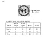
- FIG. 7 is a view illustrating a feature point detection region according to an embodiment of the present invention.
- FIG. 8 is a view illustrating a procedure of obtaining a result of recognition according to an embodiment of the present invention.
- FIG. 1 is a view schematically illustrating the configuration of a speed limit sign recognition system according to an embodiment of the present invention.
- a speed limit sign recognition system 100 includes an image acquisition unit 110 , a traffic sign detector 120 , a recognition unit 130 , a tracking unit 140 , and a decision unit 150 .
- the image acquisition unit 110 acquires a front image using a front camera.
- the traffic sign detector 120 detects a traffic sign from the acquired front image.
- the traffic sign detector 120 performs a detection operation on a traffic sign using a Haar-Feature based Viola-Jones Adaptive Boosting (Adaboost) algorithm, which is used for object detection.
- Adaboost Viola-Jones Adaptive Boosting
- the Adaptive Boosting algorithm includes a plurality of strong classifiers having a cascade structure, and is to identify whether an input image corresponds to a “traffic sign” or a “non-traffic sign”.
- the adaptive boosting algorithm includes: a traffic sign training (sample training) step of training the traffic sign detector using a traffic sign image (positive sample) of an actual recognition target, and a non-traffic sign image (negative sample); and a scan-window search step of determining whether a sub-window, which is received using a scan-window search scheme with respect to a region of interest (ROI) of a front image, corresponds to an actual “traffic sign” or a “non-traffic sign”.
- a traffic sign training sample training
- a scan-window search step of determining whether a sub-window, which is received using a scan-window search scheme with respect to a region of interest (ROI) of a front image, corresponds to an actual “traffic sign” or a “non-traffic sign”.
- ROI region of interest
- the traffic sign image (positive sample) is obtained by adding one or two margin pixels to an extracted image and then normalizing the image into a size of 20 ⁇ 20, and the non-traffic sign image (negative sample) is randomly extracted from an image which does not include a traffic sign.
- the traffic sign detector can be trained with traffic sign images (positive samples) and non-traffic sign images (negative samples) which are in a ratio of 1:2 in number.
- the traffic sign detector 120 may include a horizontal detector and a vertical detector.
- the horizontal detector has been trained only for a part constituted by 20 horizontal and 10 vertical in an image normalized into a size of 20 ⁇ 20
- the vertical detector has been trained only for a part constituted by 10 horizontal and 20 vertical in an image normalized into a size of 20 ⁇ 20.
- the traffic sign detector 120 detects a region on which an overlap occurs by the horizontal detector and the vertical detector, as an actual “traffic sign” region.
- the recognition unit 130 recognizes an internal numeral on the detected traffic sign.
- the recognition unit 130 calculates an actual limit speed using a support vector machine (SVM) with respect to a region which has been determined to be a “traffic sign” region as a detection result of the traffic sign detector.
- SVM support vector machine
- the recognition unit 130 performs: a sample training step of detecting feature points using a traffic sign image (positive sample) and a non-traffic sign image (negative sample), training with the feature points, and calculating a support vector; and a speed recognition step of calculating probabilities of belonging to the respective traffic sign image categories with inner products between the calculated support vector and feature points of an input image, and recognizing a numeral of the greatest probability value as a speed.
- a probability that an input image belongs to each traffic sign image category is calculated according to equation 1 below using a multi-SVM based on the radial basis kernel (RBF).
- k ( X i, X j ) exp( ⁇ X i ⁇ X j ⁇ 2 ) (1)
- the tracking unit 140 tracks a traffic sign which continuously appears in front images and eliminates a temporarily misrecognized object.
- the tracking unit 140 tracks a traffic sign according to template matching, sets the inside of a traffic sign recognized in an image of time “t”, as a template, limits a region of interest (ROI) in an image of time “t+1” on the basis of the moving speed of the corresponding vehicle, updates tracking contents when a traffic sign exists in the limited region of interest, and maintains a previous state when a traffic sign does not exists therein.
- ROI region of interest
- the decision unit 150 decides a result of the speed limit recognition with respect to the recognized traffic sign. In addition, the decision unit 150 determines a traffic sign to have passed and terminates the tracking when the traffic sign has not been tracked during three or more frames, accumulates probability values of the respective traffic signs which are outputted as the results of the SVM with respect to tracking-terminated objects, and determines a traffic sign having the greatest probability value as a final result.
- FIG. 2 is an operational flowchart explaining a speed limit sign recognition method using a front camera according to an embodiment of the present invention.
- the speed limit sign recognition system 100 first controls the image acquisition unit 110 to acquire a front image using a front camera in step S 210 .
- the traffic sign detector 120 detects a traffic sign from the acquired front image in step S 220 .
- the traffic sign detector 120 detects a traffic sign using a Haar-Feature based Viola-Jones Adaptive Boosting (Adaboost) algorithm used for object detection, as illustrated in FIG. 3 .
- FIG. 3 is a view illustrating Adaboost-based object detection which is applied to the present invention.
- the Adaptive Boosting algorithm includes a plurality of strong classifiers having a cascade structure, and is to identify whether an input image corresponds to a “traffic sign” or a “non-traffic sign”.
- the adaptive boosting algorithm includes: as illustrated in FIG. 4 , a traffic sign training (sample training) step of training the detector using a traffic sign image (positive sample) of an actual recognition target, and a non-traffic sign image (negative sample); and a scan-window search step of determining whether a sub-window, which is received using a scan-window search scheme with respect to a region of interest (ROI) of a front image, corresponds to an actual “traffic sign” or a “non-traffic sign”.
- FIG. 4 is a view illustrating traffic sign images (positive samples) and non-traffic sign images (negative samples) according to an embodiment of the present invention.
- traffic sign images (positive samples) have been obtained by adding one or two margin pixels to extracted images and then normalizing the respective images into a size of 20 ⁇ 20, and non-traffic sign images (negative samples) have been randomly extracted from images which do not include a traffic sign.
- 5,000 number of traffic sign images are used, and 10,000 number of non-traffic sign images are used according to each stage. Therefore, in order to acquire the best performance, it is preferred that the numbers of samples with respect to traffic sign images (positive samples) and non-traffic sign images (negative samples) are in a ratio of 1:2 in number.
- the minimum recognition rate is 99.5%
- the maximum misrecognition rate is 50%
- the number of training stages is 20.
- the minimum height of a traffic sign should be 1 m, and the maximum height thereof should be 5 m. Since traffic signs having a lower height than that stipulated in the laws can be easily found in normal construction sections, a region of interest (ROI) is set to include traffic signs having a height of at least 0.5 m and at most 5 m in consideration of the traffic signs of the construction sections. As a result of simulations with respect to multiple scale factors (1.1, 1.2. 1.3, 1.4), it was found that a scale factor of “1.2” is the most preferable in the scan-window search step.
- ROI region of interest
- the detector may include a horizontal detector and a vertical detector.
- FIG. 5 is a view explaining a horizontal detector and a vertical detector according to an embodiment of the present invention. That is to say, the horizontal detector has been trained only for a part constituted by 20 horizontal and 10 vertical in an image normalized into a size of 20 ⁇ 20, and the vertical detector has been trained only for a part constituted by 10 horizontal and 20 vertical in an image normalized into a size of 20 ⁇ 20.
- the traffic sign detector 120 detects a region on which an overlap occurs by the horizontal detector and the vertical detector, as an actual “traffic sign” region.
- the recognition unit 130 recognizes an internal numeral on the detected traffic sign in step S 230 .
- the recognition unit 130 calculates an actual limit speed using a support vector machine (SVM), as illustrated in FIG. 6 , with respect to a region which has been determined to be a “traffic sign” region as a detection result of the traffic sign detector 120 .
- SVM support vector machine
- FIG. 6 is a view showing an example of SVM-based recognition according to an embodiment of the present invention.
- the recognition unit 130 may perform: a sample training step of detecting feature points using a traffic sign image (positive sample) and a non-traffic sign image (negative sample), training with the feature points, and calculating a support vector; and a speed recognition step of calculating probabilities of belonging to the respective traffic sign image categories with inner products between the calculated support vector and feature points of an input image, and recognizing a numeral of the greatest probability value as a speed.
- the positive samples correspond to speed limit signs which are classified according to each category from 30 KPH to 110 KPH, and are normalized into images having a size of 50 ⁇ 50.
- the negative samples are configured with data misrecognized in a detection step.
- 30,000 number of positive samples are used wherein a balance between samples is not separately considered.
- FIG. 7 is a view illustrating a feature point detection region according to an embodiment of the present invention. Since all traffic signs include numeral “0” at the ends there, a remaining portion, except for a portion on which the numeral “0” is, is set as a region upon detection of feature points. In addition, a support vector to be actually used in recognition is calculated using a SVM.
- a probability that an input image belongs to each traffic sign image category is calculated according to equation 1 using a multi-SVM based on the radial basis kernel (RBF).
- FIG. 8 is a view illustrating a procedure of obtaining a result of recognition according to an embodiment of the present invention. As illustrated in FIG. 8 , when an image of a speed sign with “50” recorded thereon is classified, and it is calculated that the probability to correspond to zero “0” is 2%, the probability to correspond to speed “50” is 85%, the probability to correspond to speed “70” is 7%, and the probability to correspond to “No overtaking” is 6%, speed “50” having the greatest probability value is determined.
- the tracking unit 140 tracks a traffic sign which continuously appears in front images and eliminates a temporarily misrecognized object in step S 240 .
- the tracking unit 140 tracks a traffic sign according to template matching, sets the inside of a traffic sign recognized in an image of time “t”, as a template, limits a region of interest (ROI) in an image of time “t+1” on the basis of the moving speed of the corresponding vehicle, updates a tracker when a traffic sign exists in the limited region of interest, and maintains a previous state when a traffic sign does not exists therein.
- ROI region of interest
- the decision unit 150 decides a result of the speed limit recognition with respect to the recognized traffic sign in step S 250 .
- the decision unit 150 determines a traffic sign to have passed and terminates the tracking when the traffic sign has not been tracked during three or more frames, accumulates probability values of the respective traffic signs which are outputted as the results of the SVM with respect to tracking-terminated objects, and determines a traffic sign having the greatest probability value as a final result.
- a speed limit sign recognition system and method using a front camera which can track a traffic sign continuously appearing in images which are obtained by a photographing speed limit sign located in front of a vehicle using a camera mounted on the front of the vehicle, recognize an internal numeral of the traffic sign, and inform the driver of an actual limit speed through the recognized numeral.
- a traffic sign in an image obtained by photographing the front of a vehicle is twisted and is shown as an ellipse, it is possible to detect a speed limit sign, to extract a numeral in the traffic sign, and to recognize a limit speed.
- the present invention can be applied to a speed limit sign recognition system and method using a front camera for tracking a traffic sign continuously appearing in images which are obtained by a photographing speed limit sign located in front of a vehicle using a camera mounted on the front of the vehicle, recognizing an internal numeral of the traffic sign, and informing the driver of an actual limit speed through the recognized numeral.
Landscapes
- Engineering & Computer Science (AREA)
- Theoretical Computer Science (AREA)
- General Physics & Mathematics (AREA)
- Physics & Mathematics (AREA)
- Multimedia (AREA)
- Artificial Intelligence (AREA)
- Computer Vision & Pattern Recognition (AREA)
- Evolutionary Computation (AREA)
- Databases & Information Systems (AREA)
- Software Systems (AREA)
- Medical Informatics (AREA)
- General Health & Medical Sciences (AREA)
- Health & Medical Sciences (AREA)
- Computing Systems (AREA)
- Data Mining & Analysis (AREA)
- Life Sciences & Earth Sciences (AREA)
- Bioinformatics & Cheminformatics (AREA)
- Bioinformatics & Computational Biology (AREA)
- Evolutionary Biology (AREA)
- General Engineering & Computer Science (AREA)
- Image Analysis (AREA)
- Traffic Control Systems (AREA)
Abstract
Description
k(X i, X j)=exp(−γ∥X i −X j∥2) (1)
Claims (20)
Applications Claiming Priority (2)
| Application Number | Priority Date | Filing Date | Title |
|---|---|---|---|
| KR10-2014-0006039 | 2014-01-17 | ||
| KR1020140006039A KR101912914B1 (en) | 2014-01-17 | 2014-01-17 | Method and system for recognition of speed limit sign using front camera |
Publications (2)
| Publication Number | Publication Date |
|---|---|
| US20150206018A1 US20150206018A1 (en) | 2015-07-23 |
| US9311543B2 true US9311543B2 (en) | 2016-04-12 |
Family
ID=53545068
Family Applications (1)
| Application Number | Title | Priority Date | Filing Date |
|---|---|---|---|
| US14/267,338 Active US9311543B2 (en) | 2014-01-17 | 2014-05-01 | System and method for recognizing speed limit sign using front camera |
Country Status (2)
| Country | Link |
|---|---|
| US (1) | US9311543B2 (en) |
| KR (1) | KR101912914B1 (en) |
Cited By (4)
| Publication number | Priority date | Publication date | Assignee | Title |
|---|---|---|---|---|
| US20170217435A1 (en) * | 2016-01-30 | 2017-08-03 | Bendix Commercial Vehicle Systems Llc | System and Method for Providing a Speed Warning and Speed Control |
| CN107133568A (en) * | 2017-03-31 | 2017-09-05 | 浙江零跑科技有限公司 | A kind of speed limit prompting and hypervelocity alarm method based on vehicle-mounted forward sight camera |
| US20200192398A1 (en) * | 2018-12-14 | 2020-06-18 | Waymo Llc | Detecting Unfamiliar Signs |
| US10990835B2 (en) * | 2017-01-25 | 2021-04-27 | Wuhan Jimu Intelligent Technology Co., Ltd. | Road sign recognition method and system |
Families Citing this family (15)
| Publication number | Priority date | Publication date | Assignee | Title |
|---|---|---|---|---|
| SG11201704076YA (en) * | 2014-11-18 | 2017-06-29 | Agency Science Tech & Res | Method and device for traffic sign recognition |
| US10586102B2 (en) * | 2015-08-18 | 2020-03-10 | Qualcomm Incorporated | Systems and methods for object tracking |
| KR102415503B1 (en) * | 2015-08-21 | 2022-07-01 | 삼성전자주식회사 | Method for training classifier and detecting object |
| JP6319712B2 (en) * | 2015-09-15 | 2018-05-09 | マツダ株式会社 | Sign recognition display device |
| JP6255002B2 (en) * | 2015-12-22 | 2017-12-27 | 本田技研工業株式会社 | Vehicle sign display device and method |
| KR101718734B1 (en) * | 2016-04-19 | 2017-03-22 | 현대자동차주식회사 | A broadcast signal receiving apparatus, a vehicle with the broadcast signal receiving apparatus, a method for controlling the broadcast signal receiving apparatus and a method for controlling the vehicle |
| US10276043B2 (en) * | 2016-12-22 | 2019-04-30 | GM Global Technology Operations LLC | Vehicle system using vehicle-to-infrastructure and sensor information |
| KR101834778B1 (en) | 2017-05-30 | 2018-03-07 | 만도헬라일렉트로닉스(주) | Apparatus for recognizing traffic sign and method thereof |
| CN107798291B (en) * | 2017-09-18 | 2019-05-10 | 广州鹰瞰信息科技有限公司 | A kind of speed limit index identification method, device and system |
| CN112906424B (en) * | 2019-11-19 | 2023-10-31 | 上海高德威智能交通系统有限公司 | Image recognition methods, devices and equipment |
| CN110889378B (en) * | 2019-11-28 | 2023-06-09 | 湖南率为控制科技有限公司 | A multi-view fusion traffic sign detection and recognition method and system |
| CN112507902A (en) * | 2020-12-15 | 2021-03-16 | 深圳市城市交通规划设计研究中心股份有限公司 | Traffic sign abnormality detection method, computer device, and storage medium |
| KR102474728B1 (en) * | 2020-12-31 | 2022-12-06 | 주식회사 유라코퍼레이션 | Drive video record system and method thereof |
| CN113793279B (en) * | 2021-09-14 | 2022-11-08 | 东南大学 | Data enhancement method for traffic sign target detection field |
| KR102935756B1 (en) * | 2024-09-02 | 2026-03-06 | (주)시스콘로보틱스 | Robot system implementing detection of docking target and prediction of relative pose of robot to the docking target based on observation to the docking target |
Citations (5)
| Publication number | Priority date | Publication date | Assignee | Title |
|---|---|---|---|---|
| US20080137908A1 (en) * | 2006-12-06 | 2008-06-12 | Mobileye Technologies Ltd. | Detecting and recognizing traffic signs |
| US20110249867A1 (en) * | 2010-04-13 | 2011-10-13 | International Business Machines Corporation | Detection of objects in digital images |
| US20110249862A1 (en) * | 2010-04-09 | 2011-10-13 | Kabushiki Kaisha Toshiba | Image display device, image display method, and image display program |
| US20130163896A1 (en) * | 2011-12-24 | 2013-06-27 | Ecole De Technologie Superieure | Image registration method and system robust to noise |
| US20140079287A1 (en) * | 2012-09-18 | 2014-03-20 | Seebyte Limited et al. | Sonar imaging |
Family Cites Families (2)
| Publication number | Priority date | Publication date | Assignee | Title |
|---|---|---|---|---|
| US7466841B2 (en) * | 2004-08-16 | 2008-12-16 | Siemens Corporate Research, Inc. | Method for traffic sign detection |
| WO2013026205A1 (en) * | 2011-08-25 | 2013-02-28 | Harman International (Shanghai) Management Co., Ltd. | System and method for detecting and recognizing rectangular traffic signs |
-
2014
- 2014-01-17 KR KR1020140006039A patent/KR101912914B1/en active Active
- 2014-05-01 US US14/267,338 patent/US9311543B2/en active Active
Patent Citations (5)
| Publication number | Priority date | Publication date | Assignee | Title |
|---|---|---|---|---|
| US20080137908A1 (en) * | 2006-12-06 | 2008-06-12 | Mobileye Technologies Ltd. | Detecting and recognizing traffic signs |
| US20110249862A1 (en) * | 2010-04-09 | 2011-10-13 | Kabushiki Kaisha Toshiba | Image display device, image display method, and image display program |
| US20110249867A1 (en) * | 2010-04-13 | 2011-10-13 | International Business Machines Corporation | Detection of objects in digital images |
| US20130163896A1 (en) * | 2011-12-24 | 2013-06-27 | Ecole De Technologie Superieure | Image registration method and system robust to noise |
| US20140079287A1 (en) * | 2012-09-18 | 2014-03-20 | Seebyte Limited et al. | Sonar imaging |
Non-Patent Citations (4)
| Title |
|---|
| "Speed Limit Sign Recognition System Using Front Camera" Published on May 2, 2013 by Young-Ha Cho; Chae-Seok Lim; Min-Woo Park. Its machine translation provided by Google Translate. |
| Ach et al, "Real-time Detection of Traffic Signs on a Multi-Core Processor," 2008, IEEE Intelligent Vehicles Symposium, pp. 307-312. * |
| Gilani, "Road Sign Recognition based on Invariant Features using Support Vector Machine," 2007, pp. i-vii and 1-79. * |
| Møgelmose et al, "Traffic Sign Detection and Analysis: Recent Studies and Emerging Trends," 2012, 15th International IEEE Conference on Intelligent Transportation Systems, pp. 1310-1314. * |
Cited By (7)
| Publication number | Priority date | Publication date | Assignee | Title |
|---|---|---|---|---|
| US20170217435A1 (en) * | 2016-01-30 | 2017-08-03 | Bendix Commercial Vehicle Systems Llc | System and Method for Providing a Speed Warning and Speed Control |
| US9937923B2 (en) * | 2016-01-30 | 2018-04-10 | Bendix Commercial Vehicle Systems Llc | System and method for providing a speed warning and speed control |
| US10990835B2 (en) * | 2017-01-25 | 2021-04-27 | Wuhan Jimu Intelligent Technology Co., Ltd. | Road sign recognition method and system |
| CN107133568A (en) * | 2017-03-31 | 2017-09-05 | 浙江零跑科技有限公司 | A kind of speed limit prompting and hypervelocity alarm method based on vehicle-mounted forward sight camera |
| US20200192398A1 (en) * | 2018-12-14 | 2020-06-18 | Waymo Llc | Detecting Unfamiliar Signs |
| US10928828B2 (en) * | 2018-12-14 | 2021-02-23 | Waymo Llc | Detecting unfamiliar signs |
| US11836955B2 (en) | 2018-12-14 | 2023-12-05 | Waymo Llc | Detecting unfamiliar signs |
Also Published As
| Publication number | Publication date |
|---|---|
| KR101912914B1 (en) | 2018-10-29 |
| US20150206018A1 (en) | 2015-07-23 |
| KR20150085988A (en) | 2015-07-27 |
Similar Documents
| Publication | Publication Date | Title |
|---|---|---|
| US9311543B2 (en) | System and method for recognizing speed limit sign using front camera | |
| EP3338248B1 (en) | Systems and methods for object tracking | |
| US10025998B1 (en) | Object detection using candidate object alignment | |
| US8705793B2 (en) | Object tracking by hierarchical association of detection responses | |
| US10380434B2 (en) | Vehicle detection system and method | |
| US20180181822A1 (en) | Hierarchical system for detecting object with parallel architecture and hierarchical method thereof | |
| US20180204076A1 (en) | Moving object detection and classification image analysis methods and systems | |
| KR101596299B1 (en) | Apparatus and Method for recognizing traffic sign board | |
| Kosaka et al. | Vision-based nighttime vehicle detection using CenSurE and SVM | |
| US9626599B2 (en) | Reconfigurable clear path detection system | |
| De Paula et al. | Real-time detection and classification of road lane markings | |
| CN104156734B (en) | A kind of complete autonomous on-line study method based on random fern grader | |
| CN109284664B (en) | Driver assistance systems and guardrail detection methods | |
| Zou et al. | Robust nighttime vehicle detection by tracking and grouping headlights | |
| Meuter et al. | A decision fusion and reasoning module for a traffic sign recognition system | |
| Padmaja et al. | A novel design of autonomous cars using IoT and visual features | |
| CN107133970A (en) | Online multi-object tracking method and device based on movable information | |
| Jurić et al. | A method for on-road night-time vehicle headlight detection and tracking | |
| JP2014059655A (en) | Road situation-monitoring device, and road situation-monitoring method | |
| US20120189161A1 (en) | Visual attention apparatus and control method based on mind awareness and display apparatus using the visual attention apparatus | |
| JP2016012303A (en) | Target article recognition apparatus | |
| KR101936108B1 (en) | Method and apparatus for detecting traffic sign | |
| Kavitha et al. | Traffic sign recognition and voice-activated driving assistance using Raspberry Pi | |
| Baek et al. | Fast and reliable two-wheeler detection algorithm for blind spot detection systems | |
| US20240005668A1 (en) | Vehicle and Control Method Thereof |
Legal Events
| Date | Code | Title | Description |
|---|---|---|---|
| AS | Assignment |
Owner name: MANDO CORPORATION, KOREA, REPUBLIC OF Free format text: ASSIGNMENT OF ASSIGNORS INTEREST;ASSIGNORS:CHO, YOUNG HA;PARK, MIN WOO;LIM, CHAE SEOK;REEL/FRAME:035431/0060 Effective date: 20140730 |
|
| FEPP | Fee payment procedure |
Free format text: PAYOR NUMBER ASSIGNED (ORIGINAL EVENT CODE: ASPN); ENTITY STATUS OF PATENT OWNER: LARGE ENTITY |
|
| STCF | Information on status: patent grant |
Free format text: PATENTED CASE |
|
| MAFP | Maintenance fee payment |
Free format text: PAYMENT OF MAINTENANCE FEE, 4TH YEAR, LARGE ENTITY (ORIGINAL EVENT CODE: M1551); ENTITY STATUS OF PATENT OWNER: LARGE ENTITY Year of fee payment: 4 |
|
| AS | Assignment |
Owner name: MANDO MOBILITY SOLUTIONS CORPORATION, KOREA, REPUBLIC OF Free format text: ASSIGNMENT OF ASSIGNORS INTEREST;ASSIGNOR:MANDO CORPORATION;REEL/FRAME:058158/0300 Effective date: 20211026 |
|
| AS | Assignment |
Owner name: HL KLEMOVE CORP., KOREA, REPUBLIC OF Free format text: MERGER;ASSIGNOR:MANDO MOBILITY SOLUTIONS CORPORATION;REEL/FRAME:061375/0680 Effective date: 20211202 |
|
| AS | Assignment |
Owner name: HL MANDO CORPORATION, KOREA, REPUBLIC OF Free format text: CHANGE OF NAME;ASSIGNOR:MANDO CORPORATION;REEL/FRAME:062152/0127 Effective date: 20220905 |
|
| MAFP | Maintenance fee payment |
Free format text: PAYMENT OF MAINTENANCE FEE, 8TH YEAR, LARGE ENTITY (ORIGINAL EVENT CODE: M1552); ENTITY STATUS OF PATENT OWNER: LARGE ENTITY Year of fee payment: 8 |