US931097A - Car-coupling. - Google Patents
Car-coupling. Download PDFInfo
- Publication number
- US931097A US931097A US31381706A US1906313817A US931097A US 931097 A US931097 A US 931097A US 31381706 A US31381706 A US 31381706A US 1906313817 A US1906313817 A US 1906313817A US 931097 A US931097 A US 931097A
- Authority
- US
- United States
- Prior art keywords
- knuckle
- arm
- locking
- block
- draw
- Prior art date
- Legal status (The legal status is an assumption and is not a legal conclusion. Google has not performed a legal analysis and makes no representation as to the accuracy of the status listed.)
- Expired - Lifetime
Links
- 238000010168 coupling process Methods 0.000 title description 28
- 238000005859 coupling reaction Methods 0.000 title description 28
- 230000008878 coupling Effects 0.000 description 25
- 230000033001 locomotion Effects 0.000 description 12
- 238000010276 construction Methods 0.000 description 5
- 238000009825 accumulation Methods 0.000 description 1
- 238000005266 casting Methods 0.000 description 1
- 239000000428 dust Substances 0.000 description 1
- 230000002452 interceptive effect Effects 0.000 description 1
- 230000003534 oscillatory effect Effects 0.000 description 1
- 230000000717 retained effect Effects 0.000 description 1
- 238000000926 separation method Methods 0.000 description 1
- 239000007787 solid Substances 0.000 description 1
Images
Classifications
-
- B—PERFORMING OPERATIONS; TRANSPORTING
- B60—VEHICLES IN GENERAL
- B60D—VEHICLE CONNECTIONS
- B60D1/00—Traction couplings; Hitches; Draw-gear; Towing devices
Definitions
- the invention relates to improvements in car couplings.
- the object of the present invention is to improve the construction of car couplings, and to provide a simple, and comparatively inexpensive one of great strength and durability, capable of" coupling automatically, and adapted to be readily uncoupled without going between the cars.
- A. further object of the invention is to provide a car coupling having means for positively opening the knuckle to set the same for automatic coupling.
- not her object of the invention is to provide a locking block operating device, adapted to lock the locking block in engagement with the knuckle, and capable also of supporting the. saidlocking block in an elevated position until the arm of the knuckle, in the opening movement of the latter, passes outward beneath the locking block.
- a knuckle opening lever of simple construction comprising a single integral casting, having one end con- Sl'lllti ed to move the locking devices or looking block to lock set position, and having a tongue or arm to engage the rear of the knuckle tail to force the knuckle open.
- the locking device is so arranged that it can be moved by the operator from the locked position while the coupler is closed, to an unlocked position in which it may be retained while the coupler re mains in closed position, whereby the cars may be uncoupled without the necessity of i'm nually maintaining the lock in raised or unlocking position during their separation.
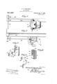
- Figure 1 is a front elevation of the front of a car provided with an automatic car coupling constructed in accordance with this invention.
- Fig. 2 is a plan view of the same.
- Fig. 3 is a longitudinal sectional view of the car coupling, the knuckle being locked.
- Fig. 4 is a horizontal sectional View of the same.
- Fig. 5 is a transverse sectional View on the line 55 of Fig. 4.
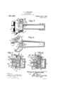
- Fig. 6 is a transverse sectionalview, illustrating the manner of supporting the locking block in an elevated position.
- Fig. 7 is detail perspective View of the knuckle.
- Fig. 8 is a similar view of the vertically movable locking block.
- Fig. 9 is a detail perspective view of the combined knuckle-opener and locking block actuating and locking device.
- the draw-head designates a draw-head, having a guard arm 2 at one side, and provided at the opposite side with upper and lower eyes 321ml 4, for the reception of a knuckle pin 5, which pivots a knuckle 6 to the draw-head.
- the draw-head is provided at the side adjacent the guard arm With'a vertical wall 7, and it has a rear transverse wall 8, arran ed at right angles to the side wall 7, and a apted to assist in guiding a vertically movable locking block 9, which also operates in a vertical guide-way 10, formed in the top of the draw head.
- the top of the draw-head is closed to prevent dust and other accumulation from entering the'draw-hea-d and interfering with the operation of the mechanism.
- the guide-way 10 is provided with vertical front, and rear walls, and with a vertical side wall, the side and rear walls forming continuations of the side and rear Walls 7 and 8 of the draw-head.
- the locking block which is substantially oblong, is rounded at the bottom at one side at 11 contiguous to the arm 12 of the knuckleto form a bearing portion for the reception of an inwardly extending arm 16, of a combined knuckle-opening and locking block operating and locking device 17.
- the arm 16 inclines downwardly and inwardly when the knuckle is closed and locked, as clearly illus trated in Fig. 5 of the drawings, and it is provided at its engaging end with a projection or nose 16*, forming a prolongation of the arm 16 and arranged flush with the upper face of the same and forming an end recess at its lower face.
- the inner wall of the recess of the'locking block is provided above and below the upper and lower shoulders 14 and 15 with horizontal grooves or recesses- 14c and 15, which fornrupper and lower portions that conform to the configuration of the engaging end of the arm 16, whereby the latter is adapted to interlock with the upper and lower portions...nf the locking block.
- the knuekde opening and locking block engaging device 17 consists of a lever, having an intermediate curved body portion 18, an
- The'lever is also provided with an upper outwardly extendingop'erating' arm 20, arranged at an angle to the upper inwardly extending locking block engaging arm 16.
- the curved body portion 18 of the lever is "arranged. on a round journal or bearin 21, preferably cast integral withthe drawead, and arranged horizontally at one side thereof, at a point above the arm of the knuckle, when the lat ter is closed.
- the draw-head is provided above and below the journal or bearing portion 21 with openings '22 and 23.
- the up per opening receives a connecting bar .Z-l, which is arranged at a slight inclination and which extends from the operating arm 20 to an operating lever 25.
- the operating lever 25 is fulcrumed at its upper end on a stud 26 of the car 27, and it is connected at an intermediate pointwith the outer -end of the bar 24. It is preferably provided with a stud 28 to receive the outer end of the bar 2%, suitable keys being provided for retaining the lever on the stud 2(3, and the outer end of the bar on the stud 28 of the lever.
- the operating arm is slotted or bifurcated to'receive the inner end of the bar Q-l, which is connected to the operating arm by a suitable pivot
- the curved body portion 13 is arranged on the journal or bearing portion at the lower side thereof, when the knuckle is, closed, and locked, as shown in Fig. 5, and it is adapted to slide or par- -tially rotate upwardly to raise the, locking 23 of the draw-head, whereby the knuckle is positively intcrlocl ted with the adjacent side of the draw-head, and isefl'cctually prevented from being pulled out, should the knuckle-pin break.
- the projecting horn or portion 31 is curved or beveled at the upper side, and is provided with a concave bearing face 32, which conforms to the configuration of the lower knuckle-opening arm 1!),
- the knuckle-opening arm is swung inwardly and engages the arm of the knuckle and positively opens the latter.
- This movement simultaneously raises the locking-block, through the engagement of the same with the upper inwardly extending arm 16, and the arm of the knuckle passes beneath the locking-block, and supports the same in an elevated position.
- the parts are then in position for automatic coupling, and when the knuckle closes, its arm is withdrawn from beneath the locking-block, which drops into engagement with the arm of the knuckle.
- the rotary movementof the knuckleopening and locking-block engaging device is limited in each direction by a stop 33, projecting from. the bearing or journal 21 of the draw-head, and consisting preferably ar pin or stud seated in a recess or socket of the journal or hearing portion 21.
- the locking-block is prevented from dropping out of engagement with the arm 16 by means of a cotter-pin 3 1, which-extends across the bottom openlng 35 of the draw head, and is or may be provided with an oil?- broken and fail to limit the movement of the knuckle-opening and locking-block engaging device 17.
- the parts are assembled before the knuckle is pivoted to the draw-head.
- the knuckleopening and locking-block engaging device is first placed in position through the upper opening, and it is arrangedwith the knuckle engaging portion in substantially a horizon tal position. This will permit the lockingblock to be readily introduced into the drawhead through the bottom opening.
- the knuckle is then placed in position, and the cotter-pin is passed through the perforations provided at the bottom of the drawhead for its reception.
- the parts are removed in reverse order.
- the car coupling is exceedingly simple and inexpensivein construction, and that the means for locking the knuckle. and for opening the same and for retaining the locking device in engagement with the knuckle, consists of two parts only, the locking-block and the lever 1.7. It will also be clear that as the locking-block has a solid lower knuckle engaging portion, it is not liable to become broken, and that, after the parts are locked, the lever 17 is relieved of all strain. The inwardly extending arm of the lever 17 operates to prevent the locking-bloek from being accidentally jarred orthrown out of engagement with the arm of the knuckle. The arm of the knuckle limits the closing movement of the same, so that suflicient space is rovided for the reception of the knuckle 0 another draw-head.
- a draw-head a pivoted knuckle, a locking block movable into and out of engagement with the knuckle, and a lever having an arm arranged to move the locking device into and out 0t engagement with the knuckle and interposed between a fixed portion of the drawhead. and the said locking block, when the knuckle is closed, to retain the locking block in engagement with the knuckle.
- a car coupling the combination of a pivoted knuckle, a locking device slidable upwardlyand downwardly to release and engage the knuckle, said locking device being provided with a recess at one side between the top and bottom thereof, and a lever having knuckle-opening means and extending into the recess of the locking-block, whereby it is adapted, when oscillated, to raise and lower-the said block.
- a draw-head a pivoted knuckle having a horn extending through one side of the drawhead, a locking device for engaging the knuckle, and a lever provided with means for-operating the locking device and having an arm arranged to engage the horn of the knuckle for opening the same.
- a drawrhead having a horizontal journal, a pivoted knuckle, a vertically movable locking-block for engaging the knuckle, and a lever having a curved portion conforming to the configuration of and arranged on the journal portion of the draw-head, said lever being also provided with an arm for operating the locking device.
- a draw-head having a horizontal journal, at pivoted knuckle, a vertically 'movable locking-block. for engaging the knuckle, and a lever having a curved portion conforming to the configuration of and arranged on the journal portion of the draw-head, said lever being also provided with an arm for operating the locking device and having means for directly engaging the knuckle for opening the same.
- a draw-head having an integral horizontal journal, and provided above and below the same with openings, a pivoted knuckle having a horn extending through the lower opening, a locking device, and a lever having a curved face to fit the ournal of the draw-head, and provided with a lower por- 130' tion operating in the lower opening and arranged to engage the horn of the knuckle to open the latter, said lever being also provided with upper arms extending inwardly and outwardly, one of the arms being ar-v ranged to operate the locking device, and the other arm being arranged to operate in the upper opening of the draw-head.
- a draw-head having an integral horizontal journal, and provided above and below the same with openings, a pivoted knuckle having a horn extending through the lower opening, a locking device, a lever having a curved face to fit the journal of the drawhead, and provided with a lower portion operating in the lower opening and arranged to engage the horn of the knuckle to open the latter, said lever being also provided with upper arms extending inwardly and outwardly, one of the arms being arranged to operate the locking device, and the other arm being arranged to operate in the upper opening of the draw-head, and a stop located on the journal portion of'the drawhead and arranged to be engaged by the knuckle-opening arm of the lever and by the outwardly extending upper arm.
- a draw-head a pivoted knuckle, a locking block movable upwardly and downwardly to releaseand engage the knuckle
- an operating device having an oscillatory arm arranged to engage the locking blockto raise and lower the same, said arm when at the limit of its downward movement being arranged to lock the block in engagement with the knuckle, and when at the limit of its upward movement being arranged to support the block in an elevated position.
- a 7 car coupling the combination with a pivoted knuckle, and a locking block movable upwardly and downwardly, of an operating lever provided with knuckle opening means and having an arm for raising and lowering the locking block, said arm being arranged at. an inclination when at the limit of its movement in either direction, whereby it is adapted to support the block in an elevated position and lock the block against upward movement.
- a pivoted knuckle a locking device movable upwardly and downwardly to release and engage the knuckle
- an operating lever provided with means for opening the knuckle and for raising and lowering the locking tegral lever having one end adapted to move the locking device to a position where it will be supported and will release the knuckle
- said lever having an arm near the other end
Landscapes
- Engineering & Computer Science (AREA)
- Transportation (AREA)
- Mechanical Engineering (AREA)
- Buckles (AREA)
Description
G. E. TOMLINSON.
CAR COUPLING.
APPLICATION FILED APR. 26. 1900.
931,097. Patented Aug. 17, 1909.
2 SHEETS-SHEET 1.
G. E. TOMLlNSON.
GAR COUPLING.
APPLIGATION FILED APR. 26.1906.
Patented Aug. 17, '1909.
2 SHEETS-SHEET 2.
Shim-H fez, IZJ'UIU GEORGE E. TOMLINSON, OF PEKIN, ILLINOIS.
' CAR-COUPLING.
Specification of Letters Patent.
Patented Aug. 17, icon.
Application filed April 26, 1906. Serial No. 313,817.
To all whom it may concern:
Be it known that I, GEORGE E. TOMLIN- son, a citizen of the United States, residing at l'ekin, in the county of Tazewell and tttate of Illinois, have invented a new and useful (air-coupling, of which the following is a specification.
The invention relates to improvements in car couplings. The object of the present invention: is to improve the construction of car couplings, and to provide a simple, and comparatively inexpensive one of great strength and durability, capable of" coupling automatically, and adapted to be readily uncoupled without going between the cars.
A. further object of the invention is to provide a car coupling having means for positively opening the knuckle to set the same for automatic coupling.
.\not her object of the invention is to provide a locking block operating device, adapted to lock the locking block in engagement with the knuckle, and capable also of supporting the. saidlocking block in an elevated position until the arm of the knuckle, in the opening movement of the latter, passes outward beneath the locking block.
Another important object of theinvention is theprovision of a knuckle opening lever of simple construction, comprising a single integral casting, having one end con- Sl'lllti ed to move the locking devices or looking block to lock set position, and having a tongue or arm to engage the rear of the knuckle tail to force the knuckle open. By the implication that the locking devices may be brought to lock set position I mean, of"
course. that the locking device is so arranged that it can be moved by the operator from the locked position while the coupler is closed, to an unlocked position in which it may be retained while the coupler re mains in closed position, whereby the cars may be uncoupled without the necessity of i'm nually maintaining the lock in raised or unlocking position during their separation.
\Vith these and other objects in View, the
invention consists in the construction. and novel combination and arrangement of parts, hereinafter fully described, illustrated in the accompanying drawings, and pointed out in the claims hereto appended; it being understood that various changes in the form,
proportion, size and minor details of'construction, within the scope of the claims,
may be resorted to without departing from the spirit or sacrificing any of the advantages of the invention.
in the drawings: Figure 1 is a front elevation of the front of a car provided with an automatic car coupling constructed in accordance with this invention. Fig. 2 is a plan view of the same. Fig; 3 is a longitudinal sectional view of the car coupling, the knuckle being locked. Fig. 4 is a horizontal sectional View of the same. Fig. 5 is a transverse sectional View on the line 55 of Fig. 4. Fig. 6 is a transverse sectionalview, illustrating the manner of supporting the locking block in an elevated position.
Fig. 7 is detail perspective View of the knuckle. Fig. 8 is a similar view of the vertically movable locking block. Fig. 9 is a detail perspective view of the combined knuckle-opener and locking block actuating and locking device.
Like numerals of reference designate corresponding parts in all the figures of the drawings.
1' designates a draw-head, having a guard arm 2 at one side, and provided at the opposite side with upper and lower eyes 321ml 4, for the reception of a knuckle pin 5, which pivots a knuckle 6 to the draw-head. The draw-head is provided at the side adjacent the guard arm With'a vertical wall 7, and it has a rear transverse wall 8, arran ed at right angles to the side wall 7, and a apted to assist in guiding a vertically movable locking block 9, which also operates in a vertical guide-way 10, formed in the top of the draw head. The top of the draw-head is closed to prevent dust and other accumulation from entering the'draw-hea-d and interfering with the operation of the mechanism. The guide-way 10 is provided with vertical front, and rear walls, and with a vertical side wall, the side and rear walls forming continuations of the side and rear Walls 7 and 8 of the draw-head.
The locking block, which is substantially oblong, is rounded at the bottom at one side at 11 contiguous to the arm 12 of the knuckleto form a bearing portion for the reception of an inwardly extending arm 16, of a combined knuckle-opening and locking block operating and locking device 17. The arm 16 inclines downwardly and inwardly when the knuckle is closed and locked, as clearly illus trated in Fig. 5 of the drawings, and it is provided at its engaging end with a projection or nose 16*, forming a prolongation of the arm 16 and arranged flush with the upper face of the same and forming an end recess at its lower face. The inner wall of the recess of the'locking block is provided above and below the upper and lower shoulders 14 and 15 with horizontal grooves or recesses- 14c and 15, which fornrupper and lower portions that conform to the configuration of the engaging end of the arm 16, whereby the latter is adapted to interlock with the upper and lower portions...nf the locking block. When the arm 16 of the combined knuckle opening and locking block operating device 17 is inclined downwardly and inwardly in the position illustrated in Fig. 5, it is interposed between the pivot of the combined knuckle opening and locking block operating deviceand the locking block, and thelatter is held against upward movement, and when the said arm 16 is swung upwardly from the position shown in Fig. 5, it lifts the locking block by first engaging the shoulder 14: and a continued upward move ment carries the arm 16 into engagement with the grooved or recessed portion 14, whereby the locking block is held in an elevated position. The opening movement of the knuckle carries the arm 12 into engagement with the beveled or rounded corner 11, and thereby-disengages the arm 16 from the lockin block and permits the arm to drop to the ower ortion of the recess 13.
The knuekde opening and locking block engaging device 17 consists of a lever, having an intermediate curved body portion 18, an
'plrlovided with areversely curved lower uckle-opening arm 19. The'lever is also provided with an upper outwardly extendingop'erating' arm 20, arranged at an angle to the upper inwardly extending locking block engaging arm 16. i The curved body portion 18 of the lever is "arranged. on a round journal or bearin 21, preferably cast integral withthe drawead, and arranged horizontally at one side thereof, at a point above the arm of the knuckle, when the lat ter is closed. The draw-head is provided above and below the journal or bearing portion 21 with openings '22 and 23. The up per opening receives a connecting bar .Z-l, which is arranged at a slight inclination and which extends from the operating arm 20 to an operating lever 25. The operating lever 25 is fulcrumed at its upper end on a stud 26 of the car 27, and it is connected at an intermediate pointwith the outer -end of the bar 24. It is preferably provided with a stud 28 to receive the outer end of the bar 2%, suitable keys being provided for retaining the lever on the stud 2(3, and the outer end of the bar on the stud 28 of the lever. The operating arm is slotted or bifurcated to'receive the inner end of the bar Q-l, which is connected to the operating arm by a suitable pivot The curved body portion 13 is arranged on the journal or bearing portion at the lower side thereof, when the knuckle is, closed, and locked, as shown in Fig. 5, and it is adapted to slide or par- -tially rotate upwardly to raise the, locking 23 of the draw-head, whereby the knuckle is positively intcrlocl ted with the adjacent side of the draw-head, and isefl'cctually prevented from being pulled out, should the knuckle-pin break. The projecting horn or portion 31 is curved or beveled at the upper side, and is provided with a concave bearing face 32, which conforms to the configuration of the lower knuckle-opening arm 1!),
and when the operating arm 20 is moved outwardly by the operatingmechanism, the knuckle-opening arm is swung inwardly and engages the arm of the knuckle and positively opens the latter. This movement simultaneously raises the locking-block, through the engagement of the same with the upper inwardly extending arm 16, and the arm of the knuckle passes beneath the locking-block, and supports the same in an elevated position. The parts are then in position for automatic coupling, and when the knuckle closes, its arm is withdrawn from beneath the locking-block, which drops into engagement with the arm of the knuckle.
The rotary movementof the knuckleopening and locking-block engaging device, is limited in each direction by a stop 33, projecting from. the bearing or journal 21 of the draw-head, and consisting preferably ar pin or stud seated in a recess or socket of the journal or hearing portion 21.
The locking-block is prevented from dropping out of engagement with the arm 16 by means of a cotter-pin 3 1, which-extends across the bottom openlng 35 of the draw head, and is or may be provided with an oil?- broken and fail to limit the movement of the knuckle-opening and locking-block engaging device 17.
The parts are assembled before the knuckle is pivoted to the draw-head. The knuckleopening and locking-block engaging device is first placed in position through the upper opening, and it is arrangedwith the knuckle engaging portion in substantially a horizon tal position. This will permit the lockingblock to be readily introduced into the drawhead through the bottom opening. The knuckle is then placed in position, and the cotter-pin is passed through the perforations provided at the bottom of the drawhead for its reception. The parts are removed in reverse order.
It will be seen that the car coupling is exceedingly simple and inexpensivein construction, and that the means for locking the knuckle. and for opening the same and for retaining the locking device in engagement with the knuckle, consists of two parts only, the locking-block and the lever 1.7. It will also be clear that as the locking-block has a solid lower knuckle engaging portion, it is not liable to become broken, and that, after the parts are locked, the lever 17 is relieved of all strain. The inwardly extending arm of the lever 17 operates to prevent the locking-bloek from being accidentally jarred orthrown out of engagement with the arm of the knuckle. The arm of the knuckle limits the closing movement of the same, so that suflicient space is rovided for the reception of the knuckle 0 another draw-head.
Having thus fully described my invention, what I claim as new, and desire to secure by Letters Patent, is
1. In a car coupling, the combination of a draw-head, a pivoted knuckle, a locking block movable into and out of engagement with the knuckle, and a lever having an arm arranged to move the locking device into and out 0t engagement with the knuckle and interposed between a fixed portion of the drawhead. and the said locking block, when the knuckle is closed, to retain the locking block in engagement with the knuckle.
2. In a car coupling, the combination of a pivoted knuckle, a locking device slidable upwardlyand downwardly to release and engage the knuckle, said locking device being provided with a recess at one side between the top and bottom thereof, and a lever having knuckle-opening means and extending into the recess of the locking-block, whereby it is adapted, when oscillated, to raise and lower-the said block.
3. In a car coupling, the combination with a draw-head, of a pivoted knuckle having a horn extending through one side of the draw-head for interlocking the knuckle with the same, a locking device for engaging the knuckle, and an operating device provided with means for operating the locking device and having means for engaging the horn of the knuckle for opening the latter.
4. In a car coupling, the combination of a draw-head, a pivoted knuckle having a horn extending through one side of the drawhead, a locking device for engaging the knuckle, and a lever provided with means for-operating the locking device and having an arm arranged to engage the horn of the knuckle for opening the same.
5: In a car coupling, the combination'ot a draw-head, a pivoted knuckle having a horn extending through one side of the drawhead when the knuckle is closed, a vertically movable locking-block, and a lever provided with an arm for raising and lowering the locking-block, said lever being also provided with an arm arranged to engage the horn of the knuckle for opening the same. I
6'. In a car coupling, the combination of a (lI'ttW-l162l(l, tl pivoted knuckle, a vertically movable locking-block having a recess and provided within the same with upper and lower shoulders, anda lever fulcrumed on the draw-head, and having an arm extending into the rece s, and arranged to engage the shoulders for raising the locking-block.
7. In a car coupling, the combination of a drawrhead having a horizontal journal, a pivoted knuckle, a vertically movable locking-block for engaging the knuckle, and a lever having a curved portion conforming to the configuration of and arranged on the journal portion of the draw-head, said lever being also provided with an arm for operating the locking device.
8. In a car coupling, the combination of a draw-head having a horizontal journal, at pivoted knuckle, a vertically 'movable locking-block. for engaging the knuckle, and a lever having a curved portion conforming to the configuration of and arranged on the journal portion of the draw-head, said lever being also provided with an arm for operating the locking device and having means for directly engaging the knuckle for opening the same.
9. In a car coupling, the combination of a draw-head having an integral horizontal journal, and provided above and below the same with openings, a pivoted knuckle having a horn extending through the lower opening, a locking device, and a lever having a curved face to fit the ournal of the draw-head, and provided with a lower por- 130' tion operating in the lower opening and arranged to engage the horn of the knuckle to open the latter, said lever being also provided with upper arms extending inwardly and outwardly, one of the arms being ar-v ranged to operate the locking device, and the other arm being arranged to operate in the upper opening of the draw-head.
10. In a car coupling, the combination of a draw-head having an integral horizontal journal, and provided above and below the same with openings, a pivoted knuckle having a horn extending through the lower opening, a locking device, a lever having a curved face to fit the journal of the drawhead, and provided with a lower portion operating in the lower opening and arranged to engage the horn of the knuckle to open the latter, said lever being also provided with upper arms extending inwardly and outwardly, one of the arms being arranged to operate the locking device, and the other arm being arranged to operate in the upper opening of the draw-head, and a stop located on the journal portion of'the drawhead and arranged to be engaged by the knuckle-opening arm of the lever and by the outwardly extending upper arm.
11. In a car coupling, the combination of a draw-head, a pivoted knuckle, a locking block movable upwardly and downwardly to releaseand engage the knuckle, and an operating device having an oscillatory arm arranged to engage the locking blockto raise and lower the same, said arm when at the limit of its downward movement being arranged to lock the block in engagement with the knuckle, and when at the limit of its upward movement being arranged to support the block in an elevated position.
12. In a car coupling, the combination of a draw-head, a pivoted knuckle, a locking block movable upwardly and downwardly to release and engage the knuckle, and a com-.
bined operating and locking lever havin an arm arranged to raise and lower-theb ock,
and provided with a projecting nose for engaging the locking block, said locking block being grooved at its upper and lower. portions to fit the engagin end of the arm,
whereby it is interlocked with the same at the limit of its upward and downward move ments to support the locking block in an elevated position, and, to lock the same in engagement with the knuckle.
13. In a car coupling, the combination with a draw-head, a pivoted knuckle having an arm, and a locking block mounted on the draw-head and movable upwardly and downwardly into and out of engagement with the knuckle, of an operating levermounted in the draw-head above the arm of the knuckle and provided with knuckle opening means and having an arm adapted to raise and lower the locking block and arranged to support the said block in an elevated position.
ii. In a 7 car coupling, the combination with a pivoted knuckle, and a locking block movable upwardly and downwardly, of an operating lever provided with knuckle opening means and having an arm for raising and lowering the locking block, said arm being arranged at. an inclination when at the limit of its movement in either direction, whereby it is adapted to support the block in an elevated position and lock the block against upward movement.
15. In a car coupling, the combination of a pivoted knuckle, a locking device movable upwardly and downwardly to release and engage the knuckle, and an operating lever provided with means for opening the knuckle and for raising and lowering the locking tegral lever having one end adapted to move the locking device to a position where it will be supported and will release the knuckle,
to engage the knuckle tail to open the knuckle.
In testimony, that I claim the foregoing as my own, I have hereto atfixed my signa- .ture in the presence of two witnesses.
GEORGE E. TOMLINSON.
\Vitnesses E. H. ZIMMER,
C. T. MoKiNsTn'Y.
device and for supporting the same in an.
said lever having an arm near the other end
Priority Applications (1)
| Application Number | Priority Date | Filing Date | Title |
|---|---|---|---|
| US31381706A US931097A (en) | 1906-04-26 | 1906-04-26 | Car-coupling. |
Applications Claiming Priority (1)
| Application Number | Priority Date | Filing Date | Title |
|---|---|---|---|
| US31381706A US931097A (en) | 1906-04-26 | 1906-04-26 | Car-coupling. |
Publications (1)
| Publication Number | Publication Date |
|---|---|
| US931097A true US931097A (en) | 1909-08-17 |
Family
ID=2999520
Family Applications (1)
| Application Number | Title | Priority Date | Filing Date |
|---|---|---|---|
| US31381706A Expired - Lifetime US931097A (en) | 1906-04-26 | 1906-04-26 | Car-coupling. |
Country Status (1)
| Country | Link |
|---|---|
| US (1) | US931097A (en) |
-
1906
- 1906-04-26 US US31381706A patent/US931097A/en not_active Expired - Lifetime
Similar Documents
| Publication | Publication Date | Title |
|---|---|---|
| US393693A (en) | Car-coupling | |
| US785086A (en) | Automatic car-coupling. | |
| US505621A (en) | Half to henry e | |
| US1033259A (en) | Car-coupling. | |
| US831249A (en) | Car-coupling. | |
| US816165A (en) | Car-coupling. | |
| US431415A (en) | Car-coupling | |
| US494219A (en) | Car-coupling | |
| US410542A (en) | dowling | |
| US751737A (en) | Car-coupling | |
| US576008A (en) | turnbull | |
| US787991A (en) | Car-coupling. | |
| US370343A (en) | Car-coupling | |
| US441624A (en) | winteenight | |
| US1045365A (en) | Car-coupling. | |
| US804031A (en) | Automatic car-coupling. | |
| US508442A (en) | Car-coupling | |
| USRE11556E (en) | Car-coupling | |
| US958359A (en) | Car-coupling. | |
| US1021412A (en) | Car-coupling. | |
| US1138650A (en) | Car-coupling. | |
| US1542303A (en) | Car coupler | |
| US1080744A (en) | Car-coupling. | |
| US718889A (en) | Car-coupling. | |
| US534217A (en) | Car-coupling |