US930650A - Low-pressure steam and analogous system. - Google Patents
Low-pressure steam and analogous system. Download PDFInfo
- Publication number
- US930650A US930650A US47221809A US1909472218A US930650A US 930650 A US930650 A US 930650A US 47221809 A US47221809 A US 47221809A US 1909472218 A US1909472218 A US 1909472218A US 930650 A US930650 A US 930650A
- Authority
- US
- United States
- Prior art keywords
- chamber
- pressure
- water
- pressure chamber
- boiler
- Prior art date
- Legal status (The legal status is an assumption and is not a legal conclusion. Google has not performed a legal analysis and makes no representation as to the accuracy of the status listed.)
- Expired - Lifetime
Links
- XLYOFNOQVPJJNP-UHFFFAOYSA-N water Substances O XLYOFNOQVPJJNP-UHFFFAOYSA-N 0.000 description 59
- 238000009833 condensation Methods 0.000 description 2
- 230000005494 condensation Effects 0.000 description 2
- 230000000994 depressogenic effect Effects 0.000 description 2
- 150000002500 ions Chemical class 0.000 description 2
- 239000002184 metal Substances 0.000 description 2
- 244000261422 Lysimachia clethroides Species 0.000 description 1
- 208000036366 Sensation of pressure Diseases 0.000 description 1
- ATJFFYVFTNAWJD-UHFFFAOYSA-N Tin Chemical compound [Sn] ATJFFYVFTNAWJD-UHFFFAOYSA-N 0.000 description 1
- 238000010276 construction Methods 0.000 description 1
- CVSVTCORWBXHQV-UHFFFAOYSA-N creatine Chemical compound NC(=[NH2+])N(C)CC([O-])=O CVSVTCORWBXHQV-UHFFFAOYSA-N 0.000 description 1
- 239000011521 glass Substances 0.000 description 1
- 239000003921 oil Substances 0.000 description 1
- 238000005192 partition Methods 0.000 description 1
- 230000005061 slumber Effects 0.000 description 1
- 238000004326 stimulated echo acquisition mode for imaging Methods 0.000 description 1
- 230000004936 stimulating effect Effects 0.000 description 1
Images

Classifications
-
- F—MECHANICAL ENGINEERING; LIGHTING; HEATING; WEAPONS; BLASTING
- F23—COMBUSTION APPARATUS; COMBUSTION PROCESSES
- F23N—REGULATING OR CONTROLLING COMBUSTION
- F23N3/00—Regulating air supply or draught
- F23N3/02—Regulating draught by direct pressure operation of single valves or dampers
Definitions
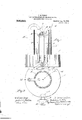
- igure 1 is an elevation of apparatus embodying my invention when there is no stear'npre'ssure.
- Fig. 2 isa plan view thereoi partly broken away.
- Fig. 3 is a section onjhne 3 -3 o'i'Fig; 1.
- Fig. 4 is an ew similar to Fig. 1, partly ,showingthe apparatus when .under.press '1 'fir ,Refci ringto the drawings
- i represents a pressure chamber which is filled with water to the proper level, as indicated in Fig. 1.
- the steam space of the pressure chamber is' connected. with the steam s ace of the steam boiler by a pipe 2 which is pitchedv toward the boiler and serves bothto introduce steam from the boiler and also to carry of? any excess waterin the pressure chamber which may have been caused by condensation of the steam.
- an expansion chamber 3 Connecting with the pressure chamber and opening into it from'the top is an expansion chamber 3 which extends down into the pressure chamber to some distance below the normal level of the water line in the pressure chamber and nearly to the bottom of saidchamber.. The upper end of the expansion chamber extends some distance above the top" 'of the pressure chamber.
- the expansion chamber is open to the atmosphere at th .top.
- valve 12 Connected with the gdg e 6 at its upper end is a valve 12 for the purpose of shutting off the steam from said gage if necessary.
- a relief pipe 13 is connected with the top oi'i the pressure chamber and extendsdown into the pressure chamber considerably'below the water level but preferably not quite so low as the expansiomchamber. It preferably rises higher than the expansion chamher and the upper end preferably terminates in a goose-neck which extends over the top oft-he expansion chamber so that any water carried up through the pipe will fall into the expansion chamber.
- a float 14 which is preferably end being of a litt e less diameter than the that is, so that the water can rise in the exansion chamber around the. float.
- This oat is preferably hollow made of tin, copp or other sheet metal, and is provided w t a weighted metal ring 15 at its lower end on sink somewhat below t. e surface of the water and keep the float in a vertical position. Normally, that is, when there is no steam pressure in the pressure chamber and the water is at its normal level in the ressure "chamber, the weight of the float will cause it to sink nearly to the bottom of the chamber.
- gage 6 will indicate the level of said chamber and the other tube is open to the. atmosphere and does not have a steam connection at the'top. hen there is any pressure in the device, the water in the tube connected top and bottom with the pressure chamber will be depressed while the one connected with the water at the bottom and open to the atmosphere at the top will be e evated. Gage'5 will indicate the level (if the water in the pressure chamber while the water in the expansion chamber. The difference in the level of the water indicates the pressure The apparatus once filled will remain sons the condensation of vapor tion to the boiler.
- the pressure chamber and pressure pipe must se ate ll'hile l.
- the invention as adapted to use in connection with the water line, an expansion chamber whose lower end opens into the pressure chamber below the normal level of the water in the pressure chamber, the upper end of the expansion chamber extendingiabove the top of sing open to the atmosphere, and a float fitting loosely within said expansion chamber, said float having a connection with a damper.
- an expansion chamber whose upper end is open to the atmosphere and wiose lower end is open to the pressure ciambcr below the normal water line in the )ressure chamber, a float fitting loosely wit in said expansion chamber, a connection connecting the float with a damper, and a relief pipe whose lower end extends down into the pressure chamber a less distance than the'lower end of the expansion chamber but below the normal level of thewate'r line and whose r upper end is open to the atmosphere;
- sion chamber and adapted to be connected with a damper.
- gage being closed to t e atmosphere and having a connection through which I the steam pressure from the boiler is conducted into the upper part of said second a e an ex ansion chamber whose .u or
- said gages having at its-u to the atmos here, an the other of sai gages being o osed to the atmos )here and having at its upper end a return tu ul'ar con nection openin into the steam space ofthe pressure cham er, an expansion chamber which surmounts the pressure chamber and whose upper end is open to the atmosphere and whose lower end extendsdown into the ressure chamber belowthe normal water ine in the pressure chamber and is 0 on at its lower end, and a pipe mounted in t e top of the pressure chamber outside of the expansion chamber, the lower end of the pipe sure chamber.
- suoftlis o'- ilexibie connection at its gages being closed to down into ibe pressure climnbei' :1 less distance than the lower end of the pension chamber but below 1 ormal level of the Water iine siui smose upper end open to the atmosphere, s iioot/ i' tti '3, lossely Within said eiipa-nsion chamber a o s conneotion connecting the float with damper. 11.
- a pres- I a pipe commotion leading from the sleom eliimiber r, L-lie boiler also she steam of the .eSulQ chamber, two mister iJOiji].
- ope into i lie gjii'osu' chamber filie zr lowel ends below ibe "a. iine in she "pie o: elioziiber,
Landscapes
- Engineering & Computer Science (AREA)
- Chemical & Material Sciences (AREA)
- Combustion & Propulsion (AREA)
- Mechanical Engineering (AREA)
- General Engineering & Computer Science (AREA)
- Control Of Steam Boilers And Waste-Gas Boilers (AREA)
Description
B. R. DOODY. LOW PRE$SURE STEAM 'ANDANALOGOUS SYSTEM.
- ABPLIUATION FILED JAN. 14, 1909.
* Patented Au 10, 1909.
, V R L Fr .llnll ii elevational "@iiiififP-ATENT OFFIC BARTHOLOMEW s. Donna"; on CANTON. MASSACHUSETTS.
.now-ennssonn's'rnej rnirp snnnoeoos srsmn.
The object of the invention is to provide a" combined dam er regulator, pressure gage water gage an safet device. In the drawings: igure 1 is an elevation of apparatus embodying my invention when there is no stear'npre'ssure. Fig. 2 isa plan view thereoi partly broken away. Fig. 3is a section onjhne 3 -3 o'i'Fig; 1. Fig. 4 is an ew similar to Fig. 1, partly ,showingthe apparatus when .under.press '1 'fir ,Refci ringto the drawings i represents a pressure chamber which is filled with water to the proper level, as indicated in Fig. 1.
"The steam space of the pressure chamber is' connected. with the steam s ace of the steam boiler by a pipe 2 which is pitchedv toward the boiler and serves bothto introduce steam from the boiler and also to carry of? any excess waterin the pressure chamber which may have been caused by condensation of the steam. Connecting with the pressure chamber and opening into it from'the top is an expansion chamber 3 which extends down into the pressure chamber to some distance below the normal level of the water line in the pressure chamber and nearly to the bottom of saidchamber.. The upper end of the expansion chamber extends some distance above the top" 'of the pressure chamber.
The expansion chamber is open to the atmosphere at th .top.
Connected was the pressure chamber at the lower part thereoi in any suitable way are two glasswater gages 5, 6, which for convenience of :connection are preferably connectcv with the pressure chamber by a fittin water gages as by-a partition 11. lhe "boiler, this pressure wi It rough pipe 2 gagefi at its uppenlend is connectedby,a re-v I "Z provided with a valve 8 to open or shuto this conneetion between the pressure cha ns 'ber andtl 'e. water gages as desired: The 11' -u'pper en the gage 5 being open to theat mosphere *at its upper end as by a vent. :10 and is shut-pit from connection with the other term the pressure chamber.
turn tube 4 with the steam space of pressure chamber 1. Any suitable tubular connecgage 6 and the steam space of the pressure chamber may be used instead of the form of construction shown. Connected with the gdg e 6 at its upper end is a valve 12 for the purpose of shutting off the steam from said gage if necessary.
. A relief pipe 13 is connected with the top oi'i the pressure chamber and extendsdown into the pressure chamber considerably'below the water level but preferably not quite so low as the expansiomchamber. It preferably rises higher than the expansion chamher and the upper end preferably terminates in a goose-neck which extends over the top oft-he expansion chamber so that any water carried up through the pipe will fall into the expansion chamber.
Fitting loosely within the expansion chamber is a float 14 which is preferably end being of a litt e less diameter than the that is, so that the water can rise in the exansion chamber around the. float. This oat is preferably hollow made of tin, copp or other sheet metal, and is provided w t a weighted metal ring 15 at its lower end on sink somewhat below t. e surface of the water and keep the float in a vertical position. Normally, that is, when there is no steam pressure in the pressure chamber and the water is at its normal level in the ressure "chamber, the weight of the float will cause it to sink nearly to the bottom of the chamber. Connected with the up r end ofthe float is a chain or other 'flexi le connection 16 which leads out offthe upper end of the expansion chamber over suitable ulleys to the dampers, draft doors, etc. on there is no steam pressure, the water in both glass gages will stand'at the same level as the we- The operation is as'followsz'We will assume that the device has been filled with .water to the proper level and that it has been connected to the steam space of a tlrua'boi er and that a fire is started under the boiler.. As the water beats and vapor arises therefrom, creatin a ressure in the force the, water downward in the. pressure formed sli htl ta ering u ward, its lower g y Y tion between the upper end of 'the water inside diameter of the expansion chamber,
the inside of the peri hery so that it will boiler b ',mealns of agpipe pitched toward float descends, the dampers and draft doors are thereby opened, the fire is stimulated, again pressure is exerted as before and so the thing goes on, the dampers and draft doors bein opened and closed, stimulating or checliing the fire as the case may be. Should there be an excess of pressure at any time the water in the pressure chamber would continue to be depressed until it had reached to the lower end of the relief pipe when the pressure will be immediately relieved through chamber by means of the goose-nec 1.
said pipe which terminates in'agoose-neck open to the atmosphere. Any water carried u ward by the escaping vapor is returned to the device through the ex ansion The gages operate as follows. At no ressure water stands at same level in botn tubes. It will be seen that both gage tubes are c0nnected at the bottom with the water in the "pressure chamber, while at the top one of i said tubes connects with the steam space ol in the system.
. gage 6 will indicate the level of said chamber and the other tube is open to the. atmosphere and does not have a steam connection at the'top. hen there is any pressure in the device, the water in the tube connected top and bottom with the pressure chamber will be depressed while the one connected with the water at the bottom and open to the atmosphere at the top will be e evated. Gage'5 will indicate the level (if the water in the pressure chamber while the water in the expansion chamber. The difference in the level of the water indicates the pressure The apparatus once filled will remain sons the condensation of vapor tion to the boiler.
will furnish a constant supply while any surplus Will be carrledoff through the connec- The pitch from the pressure 0 amber toward the oiler and enter the pressure chamber at aheight necessary to maintain the w ater line at such a level in relation to the lower end of the relief pi e and also the lower end of the expansion chamber as to seal thelower end of the relief pipe and expansion chamber up to a predetermined pressure. p
Once in operation, the apparatus is absolutely automatic, controlling dampers, indicating water level aswell as pressure, maintaining the necessary water level and reliev= ing all undue pressure.
the pressure chamber and pressure pipe must se ate ll'hile l. have especially described the invention as adapted to use in connection with the water line, an expansion chamber whose lower end opens into the pressure chamber below the normal level of the water in the pressure chamber, the upper end of the expansion chamber extendingiabove the top of sing open to the atmosphere, and a float fitting loosely within said expansion chamber, said float having a connection with a damper.
2. In combination with. a boiler, a pressure chamber, two water gages both 0 ening into the pressure chamber at their lbwer ends below the'normal water line in the pressure chamber, one of said gages having at its upper end an opening to the atmosphere, the
other of said gages being closed to the ata hot water system.
mosphere and having a connection through which the steam pressure from the boiler is conducted into the upper part of said second gage, an expansion chamber whose u per end is open to the atmosphere and w use lower end is open to the pressure chamber" below the normal water line in the ressure chamber, a float fitting loosely wit 1in said.
expansion chamber and a connection connecting the float with a damper.
3. In combination with a boiler, 'a pressure chamber, two water gages" both 0 ening into the pressure. chamber at their ower ends below the normal water line in the pressure chamber, one of said gages having at its upper end an opening to theatmosphere, the other of said gages being closed to the atmosphere and having a connctiomthrough which the steam pressure from the boiler is-.
conducted into the upper part of said second gage, an expansion chamber whose upper end is open to the atmosphere and wiose lower end is open to the pressure ciambcr below the normal water line in the )ressure chamber, a float fitting loosely wit in said expansion chamber, a connection connecting the float with a damper, and a relief pipe whose lower end extends down into the pressure chamber a less distance than the'lower end of the expansion chamber but below the normal level of thewate'r line and whose r upper end is open to the atmosphere;
4. In combination with a boiler, a pressure chamber, a pipe connection leading from the steam chamber of the boiler into the steam space of the pressure bhamber above the water line, an expansion chamber which leads out of the pressure ambushed-pet to the atmosphere, the lower end of the e} pension chamben'extcnding down below the normal wheeling in the pressure ch'amber; a relief pipe outside of the expansion eham- Y sionchamber and a flexible connection extending from said float outside of the expan'-.
sion chamber and adapted to be connected with a damper.
5. In combination with a boiler, a ressure chamber, a ipe connection leading rom the steam cham er of the boiler into the steam space of the pressure chamberabove the water line, an expansion chamber. which leads out of the ressure chamber and is open to the atmos ere, the lower end of the expan' sion cham er extending'down below theiiormal waterline in the ressurc chamber, a re; lief pi e outside of t e expansion chamber, whose ower end also extends-down into the pressure chamber below the normal level of the water lineand whose upper end is open to the atmosphere, and a float fitting loosely within said expansion chamber. said float having a connection with a damper,
6. In combination with boiler, a ressure chamber, a ipe connection leading Tom the steam chamber of the boiler into the steam space of the pressure chamber, an expansion chamber which leads out of the pressure chamber and is o e-n'to the atmosphere at its up or end, the ower end of the expansion chamber. extending downjbelo'w the normal water line, a relief pipe outside of the expansion chamber whose lower end also-extends down into the pressure chamber below the normal level'of the water line-and whose uper end is 0 on to the atmosphere, and a oat fitting oosely within said expansion chamber, said float being hollow and rovided'with a weight around the inside o its eriphery and near the lower end of the oat and a flexible connection extending out of the expansion chamber andadapted to be connected with a damper.
7.. In combination with a boiler, a ipressure chamber, a ipe connection leading "rom the steam chamber of the bolier into the pressure chamber above the water line, an expansion chamber which leads. out of the pressure chamber and whose lower end extends. down below the normal level of the'water in the pressure chamber, the upper end of the ex pansion chamber extending some distance above the top of the pressure chamber and being open to the atmosphere, a relief pipe whose lower end also extends downinto t e pressure chamber below the normal level of the water line and whose upper end is open tothe atmosphere, and a float fitting loosely within said ex ansion chamber,- said float been a fiexib e connection at its up er end seamin out of the expansionchamlier and apted' to be connected with a dampen om the steam cham er of the boiler into thesteam space of the pressure chamber, two water gages both opening into the pressure chamher at their lower ends below the water line in the chamber, one of said gages having at its upper end an opening to the atmosphere, and the other of said gages being closedto ,the atmosphere and having at its upper end a return tubular connection 0 ening into the steam space of the pressure 0 iamber, an expansion chamber which surmounts the pressure chamber and whose lower endextends down into the pressureuchamber below the normal water line in the pressure chamber, the lower end of the expansion chamber being open tothe pressure chamber and the up per end of the expansion chamber being open to the atmosphere, a float in the lower end of the expansion chamber, and a :connection lea-ling from the float to a damper.
8; In combination with a boiler, a fpressure. "chamber, a 1pc connection leading 'r 9. In combination with a boiler, a pressure 7 chamber, two water gages both opening into the pressure chamber at their lower ends below the normal water line in the pressure chamber, one of said gages having at its u per end an opening to the atmos here, t e
other of said gage being closed to t e atmosphere and having a connection through which I the steam pressure from the boiler is conducted into the upper part of said second a e an ex ansion chamber whose .u or
end is open ti) the atmosphere and W use lower end is open to the pressure chan'iber below thenormal water line in the ressure chamber, a fioatfit'ting loosely wit iin said expansion chamber and a connection connecting thefioat with a damper.
10. ,In pombination with a boiler, apressure chamber, a pipeconnection leading mm the steam chamber of the boiler into'the steamspace of the pressure chamber, two water gages both opening into the pressure chamber at their lower ends below the normal waterline in the pressure chamber one of per end an opening; l
said gages having at its-u to the atmos here, an the other of sai gages being o osed to the atmos )here and having at its upper end a return tu ul'ar con nection openin into the steam space ofthe pressure cham er, an expansion chamber which surmounts the pressure chamber and whose upper end is open to the atmosphere and whose lower end extendsdown into the ressure chamber belowthe normal water ine in the pressure chamber and is 0 on at its lower end, and a pipe mounted in t e top of the pressure chamber outside of the expansion chamber, the lower end of the pipe sure chamber.
.ivheatmosphere, suoftlis o'- ilexibie connection at its gages being closed to down into ibe pressure climnbei' :1 less distance than the lower end of the pension chamber but below 1 ormal level of the Water iine siui smose upper end open to the atmosphere, s iioot/ i' tti '3, lossely Within said eiipa-nsion chamber a o s conneotion connecting the float with damper. 11. In combination with a boiler, a pres- I a pipe commotion leading from the sleom eliimiber r, L-lie boiler also she steam of the .eSulQ chamber, two mister iJOiji]. ope: into i lie gjii'osu' chamber filie zr lowel ends below ibe "a. iine in she "pie o: elioziiber,
, y i oemg closed to the atmosphere and having is its uppei" end in returiti. tubuim' connection opening inso i-ilfi slixfifidfl'i. splice oi the p, chamber, an expansion chamber which surmounts fhe piessure chamber and Whose upper end is open to the atmosphere and whose iowsi' eno. extends down int-o tl1eoressure eimiiiboibelow 1e nornml Willie)! liiio in the pressure nbei open its lower end, and pipe in .iiited in the top oi" the pressure ciismbe'r out de of the mission. chamber vile 101i 1" cl 1 She eiue emeiiuling down into the pie M5? :1 less diessui'e obs times than she lOVJQl;Gll(li of the expansion chamber but below ilie normal level of the Water line and Whose upper end is open to the atmosphere, and a fioofi fifitiiig loosely W3 bin said expansion ehemiiver, said float having 1 upper end which extends out of he expansion ehzimoei' and is sdap-ed so be eonneeteil with a qlampei'.
12: In combii ion with s boiler, s pres? sure chamber pipe eonneotio 1 {ling from the chamber? of the boiloi inso Silo steam space of the pressure sbsmbei', two Water gages both opening into the pressure chamber at tl. lower ends beiow the. water line in the pressure slumber; both of said extending some istaiiee higher Lbsn the Water line of the essur-e chamber, one of ssiclgsges having at its upper end opening to the atmosphere and the other the M1110 311910 and having at its upper end return ubuisr oonneotion opening; into the so: in some of the pressure chamber} en erqmiision chamber which surmounbs L pressure oliombsi sud Whose upper end open to the atmosphere and Whose lower sud extends down into the Pressure chamber beiow the norms} Weber .ine in the pressure (chamber and is open st pansion elismbei', Elie pi g1 o the lower end of I I i f l f l 1 l l i i i whose lower end pressure in the elumii l l l l g i l l r 1 C0DI1UCF53IO11 at its out of we expansion chamber and is adopted to be oiineotezl with s damper.
in combination with a boiler,
is prosu'o ob ibei' i'zontoinmg Wa ter zitv a normal lbs iulec from the stemii. chuminflow, :1 giipb leading from said ember inlo the pressure oluiniber Lie water line, on expansion cliiu'uber opens into the pressure ehmnber below the normal level of the water in the pre sure ubsinloer, the upper end of 'liile eitpiiii chamber extending above the top 01 he pressure chamber, means connected with the pressure el'uimbei; to indicate the m1 and a [loss litring' msion olimnbei', said ion with u d: 'nper.
loosely within said flea-c bevii'ig ooimec 14. In ooii'ibimition sure oimnibei'fs pipe leud' 1g f 'oni the steam bomber of Lhe boiier into the steam space of the 'ii'ossure clizimoer, the pressure elunnbcr containing we er whose level is normally below the inl from the steam chamber, an erqmusion chamber connected with the ire-ssui'e chamber, siiost iijzting loosely within said N ismsion olumibei said float being provide 'Willll 20 Weight around the inside of its pctviipheiy st its lower end and lb flexible connection connecting the fiool, with a damper. combination with a boiler, a pres sure elismber oonta'ning Weber at :1 normal from the steam chamber s pipe loading from said steam chamber into the pressure el'iaimbei' above Wate line, an expsnison chamber whose loi vei' em opens into the pressure chamber below the noimai .ievel of (lie Wiltm in the iev el below the inlet of the boiier,
1) sure elm obey, the upper end of the expeiismii oils or exte iding above the top of the pressure {tllilll'lilfil till(l being open to the iu'JIl'lUL-PilGlG, a water gage opening into the Pressure 0 12m below the normal le'v'eHil the Ws no one means eonneoted tin-lim- With to indiesie tbepressuro in the chamber.
' hereof} sllixmysignotuio,
o Witnesses.
with a boiler, :1 pres
Priority Applications (1)
| Application Number | Priority Date | Filing Date | Title |
|---|---|---|---|
| US47221809A US930650A (en) | 1909-01-14 | 1909-01-14 | Low-pressure steam and analogous system. |
Applications Claiming Priority (1)
| Application Number | Priority Date | Filing Date | Title |
|---|---|---|---|
| US47221809A US930650A (en) | 1909-01-14 | 1909-01-14 | Low-pressure steam and analogous system. |
Publications (1)
| Publication Number | Publication Date |
|---|---|
| US930650A true US930650A (en) | 1909-08-10 |
Family
ID=2999073
Family Applications (1)
| Application Number | Title | Priority Date | Filing Date |
|---|---|---|---|
| US47221809A Expired - Lifetime US930650A (en) | 1909-01-14 | 1909-01-14 | Low-pressure steam and analogous system. |
Country Status (1)
| Country | Link |
|---|---|
| US (1) | US930650A (en) |
-
1909
- 1909-01-14 US US47221809A patent/US930650A/en not_active Expired - Lifetime
Similar Documents
| Publication | Publication Date | Title |
|---|---|---|
| US776106A (en) | Apparatus for raising fluids by solar heat. | |
| US91413A (en) | Improvement in safety-valves | |
| US2336646A (en) | Apparatus for digester control | |
| US1656349A (en) | Combination back pressure and vacuum relief valve | |
| US911215A (en) | Low-pressure steam and analogous heating system. | |
| US28123A (en) | Steam-boiler regulator | |
| US2320162A (en) | Air valve | |
| US2011476A (en) | Automatic fluid control and vacuum device | |
| US32237A (en) | Improved high and low water indicator for steam-boilers | |
| US2568309A (en) | Automatic bleeder for water and oil separation | |
| US1081503A (en) | Acetylene-generator. | |
| US1013356A (en) | Lamp. | |
| US1837023A (en) | Venting device for liquid and vapor apparatus | |
| US937686A (en) | Pressure-regulating apparatus. | |
| US1124225A (en) | Feed-water regulator. | |
| US1149497A (en) | Automatic high and low water alarm for boilers. | |
| US8578A (en) | Gas-regulator | |
| US1789166A (en) | Liquid-depth-indicating device | |
| US221942A (en) | Improvement in vapor-gas apparatus | |
| US1037240A (en) | Boiler feed-water regulator. | |
| US1880236A (en) | Gauge | |
| US5064117A (en) | Domestic boiler feed water gravity supply | |
| US1064806A (en) | Apparatus for heating and measuring water. | |
| US360071A (en) | Pump-regulating device | |
| SU36626A1 (en) | Safety device against pressure increase in low-pressure steam boilers |