US930581A - Controller for yarn-changers. - Google Patents
Controller for yarn-changers. Download PDFInfo
- Publication number
- US930581A US930581A US39630007A US1907396300A US930581A US 930581 A US930581 A US 930581A US 39630007 A US39630007 A US 39630007A US 1907396300 A US1907396300 A US 1907396300A US 930581 A US930581 A US 930581A
- Authority
- US
- United States
- Prior art keywords
- pattern
- lever
- yarn
- cam
- engagement
- Prior art date
- Legal status (The legal status is an assumption and is not a legal conclusion. Google has not performed a legal analysis and makes no representation as to the accuracy of the status listed.)
- Expired - Lifetime
Links
- 238000009940 knitting Methods 0.000 description 17
- 239000004744 fabric Substances 0.000 description 8
- 239000003086 colorant Substances 0.000 description 2
- 238000010276 construction Methods 0.000 description 2
- 241000949473 Correa Species 0.000 description 1
- 240000004658 Medicago sativa Species 0.000 description 1
- 230000015572 biosynthetic process Effects 0.000 description 1
- 230000007547 defect Effects 0.000 description 1
- 230000001419 dependent effect Effects 0.000 description 1
- 230000000994 depressogenic effect Effects 0.000 description 1
- 230000005484 gravity Effects 0.000 description 1
- 239000002699 waste material Substances 0.000 description 1
Images


Classifications
-
- D—TEXTILES; PAPER
- D04—BRAIDING; LACE-MAKING; KNITTING; TRIMMINGS; NON-WOVEN FABRICS
- D04B—KNITTING
- D04B15/00—Details of, or auxiliary devices incorporated in, weft knitting machines, restricted to machines of this kind
- D04B15/38—Devices for supplying, feeding, or guiding threads to needles
- D04B15/54—Thread guides
- D04B15/58—Thread guides for circular knitting machines; Thread-changing devices
Definitions
- My invention relates to controlling mechanism for thread changers on a knitting ma chine, and has for oneof its objects to pro' vide a device by means of which the thread can be accurately changed to get any desired pattern.
- irnother ol ject of the invention is to provide means by which the changes or variations of the thread changer can be quickly effected and preferably without the possi bility of making a mistake or error in adjusting the machine foruse with any desired pattern.
- :hnother object of the invention is to provide means for adjusting the parts to compensate for wear oruncvenness of any of the parts.
- tn-other object of the ii-rvention is to provide means for using any desired pattern for striping the fabric whether the fabric be plain, or fancy, as, for instance, what is known as open mesh or dropstitch.
- the pattern is preferably produced in a permanent or immutable form and is adapted to be quickly and accurately secured in position, and the parts that are adapted to coact therewith are forced to move Withsuch accuracy and precision that the goods pro prised. upon a machine equipped with my improvement will be substantially perfect.
- the part or pattern as comprising a dislnpi'eferably in the form of an annulus, having its periphery shoul dered, preferably by means of recesses.
- a member preferably in theform of a reciprocatoryrodr or finger, is connected with the yarn changer and is adjusted to engage with the shoulders of the pattern and thereby control the yarn changers.
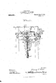
- Figure 1 is a front elevation of one form of knitting machine embodying the invention, some of the parts being omitted;
- Fig. 2 is a broken side view of the same;
- Fig. 3 is a similar View from the opposite side
- Fig. 4 is a broken top plan view of part of the operating mechanism of the machine
- Fig. 5 is a diametrical sectional view through the pattern and its support;
- Figs. 6-, 7, 8 and 9 are detail views.
- 1 indicates the frame of a knitting machine which may be of any desired construction but is preferably what is known as a circular or seamless machine.
- a pattern support preferably in: the form of a wheel, 3.
- the wheel is shown of two diameters toadapt it to knitting fabrics as hose, or half hose, of two lengths, although it can be of more or less diameters.
- the wheel or support is adapted to be driven in any suitable manner, preferably by means of a gear wheel, 4 which is mounted on a bracket 5.
- the inner edge of the plate 9 is preferably recessed with the bottom of the recess, straight and adapted to rest upon the bottom of the groove upon either side of the axis of the wheel 4, whereby the portion of the plate-9 that projects into the bore of the hub may be removed from the groove of the stud 8- by moving; either end of the plate out ward. -The wheel can then be moved laterally upon. the stud locked automatically by said plate.
- the wheel 4 is actuated by means of a pinion 11 that is mounted on a shaft 12 that receives its motion, in any desired manner, preferably from the usual ratchet mechanism 13 at one end.
- a pattern 14 mounted upon the support 3 here shown as a gear wheel is a pattern 14, shown in the present instance as an annulus, which is adapted to be removably secured thereon by means of screws, 15.
- the periphery of the pattern is provided with shoulders 16 of different heights which are adapted to control the ordinary yarn changing controllers 17, which have not been shown in detail as they form no part of the present invention.
- the element that is adapted to engage with the pattern comprises a dog or finger, 18, which is pivotally connected with a lever 19 by means of an adjustable bolt 20 and has its lower end reduced to a narrow point or nose 21, which is adapted to rest on the shoulders when the forward end of the lever 19 is depressed, or to enter the recesses between the said shoulders.
- the shoulders are formed in as many difierent heights as there are different colors of yarn that are to be used, two being'shown in the present instance, and the bottom of the deepest recess answering for the third shoulder.
- a link 22 extends from the forward end of the lever 19 to the yarn changer controlling mechanism 17 and the rear end of said lever is provided with a lug or projection 23.
- a laterally movable cam 25 is adapted to engage with the lug 23 and actuate the lever, preferably at every complete rotation of the knitting mechanism, whereby the link 22 will be moved upward to the limit at every revolution just after the yarn changers have engaged with the cams.
- This upward motion of the forward end of the lever 19 disengages the dog 18 from the pattern and permits the ratchet mechanism 13 to move the wheel 3 and pattern 14: forward one step.
- the cam 25 is moved laterally by means of a lever 26 so as to be thrown into and out of position for engaging with the lug 23and thereby permit the yarn changing mechanism to remain stationary during the formation of a portion of the fabric, as the heel of the hose or half hose as the case may be.
- the cam shifting lever 26 is turned by the movement of the heel or toe forming 1 mechanism indicated conventionally at 27 in Fig. 1 of the accompanying drawings, andshown in Figs.
- the heel-forming mechanism such. as is shown in Patent 538,518 to H. A. Houseman is thrown into operation in the ordinary or any desired manner, the means here shown being in the form of a reciprocatory push rod that is adapted to be moved into and out of engagement with a cam 30 by means of a lever 31.
- he forward end of the lever 31 is preferably inclined as at 32 and is adapted to be engaged by one or more pins 33 on the side of the pattern 1a and its other end is preferably provided with a slot 34 in which the rod 29 is reciprocated.
- the pattern is moved forward far enough after the heel mechanism begins to operate to cause the pin 33 to pass out of engagement with the lever 31 and draw the rod 29 down out of engagement with the cam 30, thereby placing the parts in position for being actuated to stripe the fabric as soon as the heel has been finished and the cam 25 has been moved back into position by the lever 26 for actuating the yarn changers.
- the nose of the forward end of the push rod 29 is preferably jointed as shown at 35 and held in its normal position by a spring 36 which permits of its being moved upward against the cam 30 in case the lever 31 should be actuated by the rotation of the pattern when the cam 30 was not in a position for permitting the end of the rod to be carried up into position for engaging with its shoulder as will be understood.
- the finger 18 is adapted to be adjusted "relatively to the shoulders of the patterns so as to cause the full width of its nose to engage with the shoulders or to pass down into a recess, thereby avoiding the possibility of its engaging with any 01": the shoulders during one revolution of the pattern and not engaging therewith on a subsequent revolution.
- this adjustment ofthe finger is accomplished by means of a rod 37 which 1s plvotally connected with the linger at 1ts forward endand has its rear end mounted upon an eccentric 38.
- the eccentric 38 can be rotated to any desired degree to properly position the nose of the finger relatively to the shoulder and then be secured in said position by means of a set-screw 89, and thus cause the fabric to always be formed true to the pattern.
- the forward end of the pin 40 is preferably provided with a cushion 43 and the spring is held in its socket by means of a cap 4% which may be adjusted as desired to the brake against the wheel.
- a suitable stop-oif mechanism is preferably provided for automatically throwing the machine out of gear.
- this mechanism comprises a stop 45 which is reinovably secured to the side of the wheel 3 in position for engaging with a push rod 46 and causing the rod to actuate the usual stop mechanism 47.
- the rod 46 is recip-- rocally mounted in a socket 48 and has one end inclined as shown at 49 for being engaged by .the stop 45 and has its other end perforated as at 50 for being connected with the stop mechanism 4'7.
- the n'racli-ine is operated and controlled y the usual mechanism and the thread changers are moved automatically so as to always produce the desired color for an particular pattern.
- the thread changer fails to operate at any particular reciprocation of the shoulder when it engages with the pattern wheel, that one defeet will be all that will appear, as the subsequent movements of the thread changers will not be varied or changed thereby.
- the pattern can be manually rotated by the operator in either direction to the starting point when a new piece of goods can be set up and completed in the same manner as though the goods had not been cast off, thereby saving the time of the operator and the wear and tear upon the machine, which must necessarily take place with other forms of pattern changers.
- I claim 1 In a knitting machine, the combination of a yarn changer, a pattern, a member connected with the yarn changer and provided with a depending element for engagement with the pattern, and a cam arranged to engage said member to move said depending element into and out of engagement with the pattern,- and means for moving said cam into and out of engagement with said member at predetermined intervals.
- a yarn changer In a knitting machine, a yarn changer, a pattern, a lever connected with the yarn changer, a bolt adjustably secured to the lever, a, dog pivotally secured to said bolt, and means for varying the angle of the dog relatively to the pattern to insure its engagement therewith on each revolution of said pattern.
- a yarn changer In a knitting machine, a yarn changer, a shouldered pattern, a lever connected at one end with the yarn changer, a dog adjustably connected with the lever at one end and having its free end in position for engaging with said shoulders, means for actuating said lever, a rod connected with the free end of said dog, and means for moving said rod endwise.
- a lever connected with the yarn changer at one end and provided with a depending member for engaging with the pattern, a laterally movable cam for engaging wit-h the opposite end of said lever to move the depending member into and out of engagement with the pattern, and means for moving said cam laterally into and out of engagement with said lever at predetermined intervals.
- a yarn changer In a knitting machine, a yarn changer, a pattern, provided with shoulders, a lever connected with the yarn changer and provided with a member in position for engaging with the pattern, a laterally movable cam in position for being moved into and out of engagement with said lever, and a lever engaging with said cam at one end and having its opposite end in position for being engaged by said shoulders for moving said cam laterally.
- a pattern a lever connected with the yarn changer at one end and provided with means for engaging with the pattern, means movable into and out of engagement with said lever for intermittently operating the same, and means for stopping the motion of the pattern and the yarn changer at predetermined periods.
- a yarn changer In a knitting machine, a yarn changer, a pattern, a gear like support for the pattern, a gear wheel adjustably mounted for actuating the support, means for actuating said gear wheel intermittently, means for controlling the yarn changer by the pattern, and means for varying the relative rate of speed between said gear wheel and the pattern support.
- a yarn changer In a knitting machine, a yarn changer, a pattern, a toothed support for the pattern of two diameters, an adjustable bracket provided with a stud, a gear wheel adjustably mounted on said stud in position for engaging with either of said toothed portions of the pattern support, a pinion for engaging with said adjustable gear wheel, and means for actuating said pinion intermittently.
Landscapes
- Engineering & Computer Science (AREA)
- Textile Engineering (AREA)
- Knitting Machines (AREA)
Description
H. H. WEST. CONTROLLER FOR YARN CHANGE-HS. APPLIOATYI'ON'PILED OCT. 7, 1907.
Patented Aug. 10, 1909.
4 SHEETSSHEET 1.
Q Ma...
ANDREW. a 0mm! 00,. Momummmms, WASHINGYDN. n a
H. H. WEST.
CONTROLLER FOR YARN GHANGERS.
APPLIUATION FILED OUT. 7, 1907.
Patented Au 10, 1909.
4 SHEETS-811111112.
amoam coz v wvcmaowo ANDREW. a GRAHAM 001 Pnon-umuamuins. WASHINGTON. n. c.
H. H. WEST.
CONTROLLER FOR'YARN (HANGERS.
APPLIUATION FILED OCT. 7, 1907. r I 930,581 Patented Aug. 10; 1909.
4 SHEETS-SHEET 3.
' .c. ANDREW. B. GRAHAM O0. PHD'IDVUTNDGRAPHERS. WASHINGTON D H. H. WEST. GONTROLLEB. FOR YARN GHANGERS.
APPLIOAHON IILEDYOOT. 7, 1907.
Patented Aug. 10, 1909.
Ire-h Parana or HARRY H WEST, OF' PLYMOUTH, PENNSYLVANIA.
CONTROLLER FOB/f Specification of Iiet'ters Patent.
Patented Aug. 10, 190 9.
Application filed October 7, 1907. Serial No; 396,300.
To all whom it may concern:
Be it known that I, HARRY I-I. Wnsr, citi zen of the United States, residing at Plymouth, in the county of Luzerne and State of Pennsylvania, have invented certain new and useful Improvements in Controllers for Yarn-Changers; and I do declare the following to be a full, clear, and exact description ofthe invention, such as will enable others skilled in the art to which it appertains to make and use the. same.
My invention relates to controlling mechanism for thread changers on a knitting ma chine, and has for oneof its objects to pro' vide a device by means of which the thread can be accurately changed to get any desired pattern.
irnother ol ject of the invention is to provide means by which the changes or variations of the thread changer can be quickly effected and preferably without the possi bility of making a mistake or error in adjusting the machine foruse with any desired pattern.
:hnother object of the invention is to provide means for adjusting the parts to compensate for wear oruncvenness of any of the parts.
tn-other object of the ii-rvention is to provide means for using any desired pattern for striping the fabric whether the fabric be plain, or fancy, as, for instance, what is known as open mesh or dropstitch.
In machines having patterns set with blocks or jacks conside able time is required to properly set up and secure the different looks or jacks in position and mistakes frequently occur either from carelessness or oversight and some of the parts are liable to become loosened and disarranged whereby the accuracy of the pattern is destroyed and the goods produced therefrom rendered useless except for waste.
In the mechanism which I have invented the pattern is preferably produced in a permanent or immutable form and is adapted to be quickly and accurately secured in position, and the parts that are adapted to coact therewith are forced to move Withsuch accuracy and precision that the goods pro duced. upon a machine equipped with my improvement will be substantially perfect.
In the accompanying embodiment of my invention I have shown. the part or pattern as comprising a dislnpi'eferably in the form of an annulus, having its periphery shoul dered, preferably by means of recesses. A member, preferably in theform of a reciprocatoryrodr or finger, is connected with the yarn changer and is adjusted to engage with the shoulders of the pattern and thereby control the yarn changers.
In the accompanying drawings which illustrate the invention, Figure 1 is a front elevation of one form of knitting machine embodying the invention, some of the parts being omitted; Fig. 2 is a broken side view of the same; Fig. 3 is a similar View from the opposite side Fig. 4 is a broken top plan view of part of the operating mechanism of the machine Fig. 5 is a diametrical sectional view through the pattern and its support; Figs. 6-, 7, 8 and 9 are detail views.
Referring more particularly to the drawings which are for illustrative purposes only and, therefore, are not drawn to any particular scale, 1 indicates the frame of a knitting machine which may be of any desired construction but is preferably what is known as a circular or seamless machine. Secured to the frame at any suitable point, pref erably by means of a depending brack t 2, is what I will call a pattern support, preferably in: the form of a wheel, 3. In the present instance the wheel is shown of two diameters toadapt it to knitting fabrics as hose, or half hose, of two lengths, although it can be of more or less diameters. The wheel or support is adapted to be driven in any suitable manner, preferably by means of a gear wheel, 4 which is mounted on a bracket 5.
The bracket is adjusted by means of a slot 6 formed therein concentric with. a shaft 12, on which it is mounted. and a bolt 7, whereby the gear wheel 3 is adapted to be-moved into engagement with either periphery of wheel 4, said wheel 4 being movably mounted upon a grooved stud 8 and adapted to be locked in either position by means of a plate 9 which fits in a slot in the hub of the Wheel 4 and is yielding y held therein'by means of a spring band,1=0-. The inner edge of the plate 9 is preferably recessed with the bottom of the recess, straight and adapted to rest upon the bottom of the groove upon either side of the axis of the wheel 4, whereby the portion of the plate-9 that projects into the bore of the hub may be removed from the groove of the stud 8- by moving; either end of the plate out ward. -The wheel can then be moved laterally upon. the stud locked automatically by said plate.
The wheel 4 is actuated by means of a pinion 11 that is mounted on a shaft 12 that receives its motion, in any desired manner, preferably from the usual ratchet mechanism 13 at one end.
Mounted upon the support 3 here shown as a gear wheel is a pattern 14, shown in the present instance as an annulus, which is adapted to be removably secured thereon by means of screws, 15. The periphery of the pattern is provided with shoulders 16 of different heights which are adapted to control the ordinary yarn changing controllers 17, which have not been shown in detail as they form no part of the present invention.
In the present construction the element that is adapted to engage with the pattern comprises a dog or finger, 18, which is pivotally connected with a lever 19 by means of an adjustable bolt 20 and has its lower end reduced to a narrow point or nose 21, which is adapted to rest on the shoulders when the forward end of the lever 19 is depressed, or to enter the recesses between the said shoulders. The shoulders are formed in as many difierent heights as there are different colors of yarn that are to be used, two being'shown in the present instance, and the bottom of the deepest recess answering for the third shoulder. A link 22 extends from the forward end of the lever 19 to the yarn changer controlling mechanism 17 and the rear end of said lever is provided with a lug or projection 23.
A laterally movable cam 25 is adapted to engage with the lug 23 and actuate the lever, preferably at every complete rotation of the knitting mechanism, whereby the link 22 will be moved upward to the limit at every revolution just after the yarn changers have engaged with the cams. This upward motion of the forward end of the lever 19 disengages the dog 18 from the pattern and permits the ratchet mechanism 13 to move the wheel 3 and pattern 14: forward one step. After this and before theknitting mechanism has completed a revolution the forward end of thelever 19 and the cams 17 are forced downwardly by gravity until the nose 21 of the dog engages with one of the shoulders or the bottom of one of the recesses and thereby fixes the cams 17 in their proper positions for actuating the yarn changers so as to throw in the desired colors to form the pattern or style of fabric being produced.
The cam 25 is moved laterally by means of a lever 26 so as to be thrown into and out of position for engaging with the lug 23and thereby permit the yarn changing mechanism to remain stationary during the formation of a portion of the fabric, as the heel of the hose or half hose as the case may be. The cam shifting lever 26 is turned by the movement of the heel or toe forming 1 mechanism indicated conventionally at 27 in Fig. 1 of the accompanying drawings, andshown in Figs. 2, 8, 9 and 10 of the Patent 538,518 to Houseman hereinafter referred to, the part corresponding to the part 27 of applicants drawings being the rod or shaft marked d and by means of which the cam 25 is moved either into or out of engagement with the lug 23 on lever 19 dependent upon the direction in which said lever 26 is moved. A spring 28 is preferably arranged between the end of the lever 26 and the heel forming mechanism at 27, whereby the danger of breakage is avoided if the cam 25 should be moved laterally when its larger operative portion were in line with the projection 23 and would engage therewith. In such a case the spring would be compressed until the cam had been rotated far enough for its larger portion to clear the projection, when the lever 26 would be moved by the spring and the cam would be drawn into position for engaging with the projection at the next revolution.
The heel-forming mechanism such. as is shown in Patent 538,518 to H. A. Houseman is thrown into operation in the ordinary or any desired manner, the means here shown being in the form of a reciprocatory push rod that is adapted to be moved into and out of engagement with a cam 30 by means of a lever 31. he forward end of the lever 31 is preferably inclined as at 32 and is adapted to be engaged by one or more pins 33 on the side of the pattern 1a and its other end is preferably provided with a slot 34 in which the rod 29 is reciprocated. \Vhen the pattern reaches the point at which the heel is to be formed one of the pins 33 engages with the lever 31 and actuates it so as to lift the forward end of the rod 39 into engagement with the cam and thereby sets the heel forming mechanism into operation and simultaneously therewith stops the ratchet mechanism 13, or pattern feed in the manner shown in Patent 538,518 to Houseman, in the manner shown.
As the rod 29 is only reciprocated once for several rotations of the knitting mechanism, generally four, the pattern is moved forward far enough after the heel mechanism begins to operate to cause the pin 33 to pass out of engagement with the lever 31 and draw the rod 29 down out of engagement with the cam 30, thereby placing the parts in position for being actuated to stripe the fabric as soon as the heel has been finished and the cam 25 has been moved back into position by the lever 26 for actuating the yarn changers. The nose of the forward end of the push rod 29 is preferably jointed as shown at 35 and held in its normal position by a spring 36 which permits of its being moved upward against the cam 30 in case the lever 31 should be actuated by the rotation of the pattern when the cam 30 was not in a position for permitting the end of the rod to be carried up into position for engaging with its shoulder as will be understood.
The finger 18 is adapted to be adjusted "relatively to the shoulders of the patterns so as to cause the full width of its nose to engage with the shoulders or to pass down into a recess, thereby avoiding the possibility of its engaging with any 01": the shoulders during one revolution of the pattern and not engaging therewith on a subsequent revolution. in the drawing this adjustment ofthe finger is accomplished by means of a rod 37 which 1s plvotally connected with the linger at 1ts forward endand has its rear end mounted upon an eccentric 38. In this manner the eccentric 38 can be rotated to any desired degree to properly position the nose of the finger relatively to the shoulder and then be secured in said position by means of a set-screw 89, and thus cause the fabric to always be formed true to the pattern.
into engagement with the side of the wheel 8 by means of a spring 42. The forward end of the pin 40 is preferably provided with a cushion 43 and the spring is held in its socket by means of a cap 4% which may be adjusted as desired to the brake against the wheel.
A suitable stop-oif mechanism is preferably provided for automatically throwing the machine out of gear. In the drawings this mechanism comprises a stop 45 which is reinovably secured to the side of the wheel 3 in position for engaging with a push rod 46 and causing the rod to actuate the usual stop mechanism 47. The rod 46 is recip-- rocally mounted in a socket 48 and has one end inclined as shown at 49 for being engaged by .the stop 45 and has its other end perforated as at 50 for being connected with the stop mechanism 4'7.
In using a machine as above described it can be quickly changed from plain to pattern work by putting on or leaving 01f the pattern, and the pattern can be changed with but little loss of time and even by the ordinary operator of the machine by removing one pattern and substituting another therefor, the patterns being provlded with any suitable distinguishing marks or characters, as, for instance, numbers by which the patterns can be known.
vary the pressure ofwith a dependlng After'the pattern has been placed in position the n'racli-ine is operated and controlled y the usual mechanism and the thread changers are moved automatically so as to always produce the desired color for an particular pattern. In case the thread changer fails to operate at any particular reciprocation of the shoulder when it engages with the pattern wheel, that one defeet will be all that will appear, as the subsequent movements of the thread changers will not be varied or changed thereby. This will prevent the fabric from being entirely ruined as frequently happens with other styles of pattern controllers, and in case the work should be cast 0d at any time from defects in the yarn, or for other reasons, the pattern can be manually rotated by the operator in either direction to the starting point when a new piece of goods can be set up and completed in the same manner as though the goods had not been cast off, thereby saving the time of the operator and the wear and tear upon the machine, which must necessarily take place with other forms of pattern changers.
Having described my invention, I claim 1. In a knitting machine, the combination of a yarn changer, a pattern, a member connected with the yarn changer and provided with a depending element for engagement with the pattern, and a cam arranged to engage said member to move said depending element into and out of engagement with the pattern,- and means for moving said cam into and out of engagement with said member at predetermined intervals.
2. In a knitting machine, the combination of a yarn changer, a pattern, a member connected with the yarn changer and provided element for engagement with the pattern, a cam arranged to engage said member to move said depending element into and out of engagement with the pattern, and a lever engaging with said cam and having one end in position for engagement by said shoulders for moving said cam.
3. In a knitting machine, a yarn changer, a pattern, a lever connected with the yarn changer, a bolt adjustably secured to the lever, a, dog pivotally secured to said bolt, and means for varying the angle of the dog relatively to the pattern to insure its engagement therewith on each revolution of said pattern.
4. In a knitting machine, a yarn changer, a shouldered pattern, a lever connected at one end with the yarn changer, a dog adjustably connected with the lever at one end and having its free end in position for engaging with said shoulders, means for actuating said lever, a rod connected with the free end of said dog, and means for moving said rod endwise.
5. In a knitting machine, a yarn changer,
a pattern, a lever connected with the yarn changer at one end and provided with a depending member for engaging with the pattern, a laterally movable cam for engaging wit-h the opposite end of said lever to move the depending member into and out of engagement with the pattern, and means for moving said cam laterally into and out of engagement with said lever at predetermined intervals.
6. In a knitting machine, a yarn changer, a pattern, provided with shoulders, a lever connected with the yarn changer and provided with a member in position for engaging with the pattern, a laterally movable cam in position for being moved into and out of engagement with said lever, and a lever engaging with said cam at one end and having its opposite end in position for being engaged by said shoulders for moving said cam laterally.
7. In a knitting machine, a yarn changer,
a pattern, a lever connected with the yarn changer at one end and provided with means for engaging with the pattern, means movable into and out of engagement with said lever for intermittently operating the same, and means for stopping the motion of the pattern and the yarn changer at predetermined periods.
8. In a knitting machine the combination with the motion changing devices, of a yarn changer, a pattern, a lever connected with the yarn changer and provided with means for engaging the pattern, a laterally movable cam for actuating said lever, and two levers, one of which engages with said cam at one end and is adapted to be engaged by one of the motion changing devices at the other end for automatically stopping the movement of the yarn changer at predetermined periods, the other of said two levers being adapted to be engaged by the pattern.
9. In a knitting machine the combination with motion changing devices, of a yarn changer, a pattern, a lever connected with the yarn changer and provided with means for engaging the pattern, a laterally movable cam for actuating said lever, two levers, one of which engages said cam at one end and is adapted to be engaged by one of the motion changing devices at the other end, the other of said two levers being adapted to be engaged by the pattern at one end, and a reciprocating push rod supported by the other end of the last mentioned lever and having its forward end jointed.
10. In a knitting machine, a yarn changer, a pattern, a gear like support for the pattern, a gear wheel adjustably mounted for actuating the support, means for actuating said gear wheel intermittently, means for controlling the yarn changer by the pattern, and means for varying the relative rate of speed between said gear wheel and the pattern support.
11. In a knitting machine, a yarn changer, a pattern, a toothed support for the pattern of two diameters, an adjustable bracket provided with a stud, a gear wheel adjustably mounted on said stud in position for engaging with either of said toothed portions of the pattern support, a pinion for engaging with said adjustable gear wheel, and means for actuating said pinion intermittently.
In testimony whereof I have hereunto set my hand in presence of two subscribing witnesses.
HARRY WE ST.
lVitnesses H. L. FREEMAN, THOMAS A. EST.
Priority Applications (1)
| Application Number | Priority Date | Filing Date | Title |
|---|---|---|---|
| US39630007A US930581A (en) | 1907-10-07 | 1907-10-07 | Controller for yarn-changers. |
Applications Claiming Priority (1)
| Application Number | Priority Date | Filing Date | Title |
|---|---|---|---|
| US39630007A US930581A (en) | 1907-10-07 | 1907-10-07 | Controller for yarn-changers. |
Publications (1)
| Publication Number | Publication Date |
|---|---|
| US930581A true US930581A (en) | 1909-08-10 |
Family
ID=2999004
Family Applications (1)
| Application Number | Title | Priority Date | Filing Date |
|---|---|---|---|
| US39630007A Expired - Lifetime US930581A (en) | 1907-10-07 | 1907-10-07 | Controller for yarn-changers. |
Country Status (1)
| Country | Link |
|---|---|
| US (1) | US930581A (en) |
-
1907
- 1907-10-07 US US39630007A patent/US930581A/en not_active Expired - Lifetime
Similar Documents
| Publication | Publication Date | Title |
|---|---|---|
| US2070762A (en) | Circular knitting machine | |
| US1569394A (en) | Buttonhole-sewing machine | |
| US1980103A (en) | Stop motion device | |
| US745449A (en) | Knitting-machine. | |
| US205663A (en) | Improvement in knitting-machines | |
| US55027A (en) | Improvement in knitting-machines | |
| US486767A (en) | clarke | |
| US1215411A (en) | Knitting-machine. | |
| US1429447A (en) | Stop motion for perforating machines | |
| US448954A (en) | The nobris peters co | |
| US387251A (en) | o neil | |
| US953248A (en) | Circular-knitting machine. | |
| US917989A (en) | Circular-knitting machine. | |
| US1439882A (en) | Thread measurer | |
| US383817A (en) | lamprey | |
| US670392A (en) | Thread-changing mechanism for knitting-machines. | |
| US768279A (en) | Thread-changing mechanism for circular-knitting machines. | |
| US932578A (en) | Knitting-machine. | |
| US250505A (en) | Knitting-machine | |
| US1198448A (en) | Take-up for circular-knitting machines. | |
| US83584A (en) | Improvement in knitting-machines | |
| US1003085A (en) | Circular-knitting machine. | |
| US676457A (en) | Machine for cutting articles from sheet material. | |
| US749062A (en) | Ihvehtor | |
| US962291A (en) | Circular-fashioning knitting-machine. |