US930571A - Type-writing machine. - Google Patents
Type-writing machine. Download PDFInfo
- Publication number
- US930571A US930571A US31037406A US1906310374A US930571A US 930571 A US930571 A US 930571A US 31037406 A US31037406 A US 31037406A US 1906310374 A US1906310374 A US 1906310374A US 930571 A US930571 A US 930571A
- Authority
- US
- United States
- Prior art keywords
- carriage
- rotary device
- hollow
- escapement
- matter
- Prior art date
- Legal status (The legal status is an assumption and is not a legal conclusion. Google has not performed a legal analysis and makes no representation as to the accuracy of the status listed.)
- Expired - Lifetime
Links
- 239000007788 liquid Substances 0.000 description 11
- 230000000979 retarding effect Effects 0.000 description 6
- 238000010276 construction Methods 0.000 description 3
- 241000721047 Danaus plexippus Species 0.000 description 2
- 230000000994 depressogenic effect Effects 0.000 description 2
- 229940099259 vaseline Drugs 0.000 description 2
- 241001052209 Cylinder Species 0.000 description 1
- 230000006835 compression Effects 0.000 description 1
- 238000007906 compression Methods 0.000 description 1
- 230000007423 decrease Effects 0.000 description 1
- 230000003247 decreasing effect Effects 0.000 description 1
- 230000000881 depressing effect Effects 0.000 description 1
- 230000003467 diminishing effect Effects 0.000 description 1
- 239000012634 fragment Substances 0.000 description 1
- QSHDDOUJBYECFT-UHFFFAOYSA-N mercury Chemical compound [Hg] QSHDDOUJBYECFT-UHFFFAOYSA-N 0.000 description 1
- 229910052753 mercury Inorganic materials 0.000 description 1
- 239000011435 rock Substances 0.000 description 1
- 230000035939 shock Effects 0.000 description 1
- 239000000126 substance Substances 0.000 description 1
Images


Classifications
-
- B—PERFORMING OPERATIONS; TRANSPORTING
- B41—PRINTING; LINING MACHINES; TYPEWRITERS; STAMPS
- B41J—TYPEWRITERS; SELECTIVE PRINTING MECHANISMS, i.e. MECHANISMS PRINTING OTHERWISE THAN FROM A FORME; CORRECTION OF TYPOGRAPHICAL ERRORS
- B41J11/00—Devices or arrangements of selective printing mechanisms, e.g. ink-jet printers or thermal printers, for supporting or handling copy material in sheet or web form
- B41J11/24—Detents, brakes, or couplings for feed rollers or platens
Definitions
- TNE55E5 g Ilm/ENTER- H. H. STEELE., TYPE WRITING MACHINE. APPLIUATION FILED APR. 6,1906.
- Type-Writ ing Machines of which the following is a specification.
- This invention relates to improvements in carriage retarding devices for ⁇ typewriting machines, and consists of the features of construction and combinations and arrangements of parts which are hereinafter described and specified inthe claims.
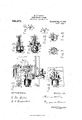
- Figure 1 is a rear and sectional elevation of the frame and partsof the mechanism of a Monarch typewriting machine to which carriag ⁇ e-retarding apparatus embodying the invention is applied;
- Fig. 2 a vertical section, on the plane indi-V cated by the broken line near the left of 1, of said frame and parts of the mechanismv of the machine, the sectional plane being seen from the right side of Vthe machine;
- Fig. 3 an enlarged vertical section of the upper rear part of the machine, the section being at right angles to the axis of theV platen, and the sectional plane being seen from the left side of the machine;
- Fig. 4 a plan of a fragment of the top-plateand of a hollow device mounted thereon which forms part of the carriage-retarding apparatus;
- Fig. 5 a vertical longitudinal section of said hollow device and side view of ⁇ a coperative rotary device confined therein;
- under-stroke machines a horizontal longitudinal section of the holl to ninnerous other machines, including such are called under-stroke machines, as,
- the carriage-retarding mechanism or apparatus in which the invention 1s embodied is attached to the top plate of the machine near its rear edge and on the right, preferably, of a vertical plane containing the axis of the escapement pinion.
- the frame of the machine is composed of the base 1 and four posts 2, only three of which are shown, and the top plate 3. On the back part of the top-plate are.
- the carriage 10 in which is mountedthe platen 11, has formed on it 'grooved guides 12 and 13, which extend from end to end of the carriage, the grooves 14 and 15 of these guides forming with the grooves 8 and 9 of the rails 5 and 6, ball or roller channels in which are shown thus supported by the rails 5 and 6 and is movable on the balls in opposite directions over the top-plate 3.
- the guides 12 and 13 are connected together by Webs 18, and between these guides extend arms 19 which are pivoted to the ends of the carriage and to whose'rear ends are aiiixed the carriage rack 20 which is movable up and down on the pivots 21 of the arms 19.
- Springs 22, acting on the arms of the rack, tend to keep the rack in the position in which it is shown in Fig. 2, 'that being its normal position.
- the rack 20 normally engages a pinion 23 which is ⁇ fast on a shaft, having a bearing in a bracket 24 aliixed to the top plate 3, and on the rear end of this shaft is an escapement wheel V25, varranged to co-act with the feed-dogs 26 and 27 (shown
- On the rock-shaft 29 is a spring 31 which tends to keep the stepping-dog 27 in engagement with a tooth of the escapement wheel 25.
- An arm 32 fast on the dogrocker, extends in front of the rock-shaft 29, and to the front end of this arm is secured a llink 33 which extends downward therefrom to the universal bar of the machine.
- the universal bar is actuated by depressing a character-key or space-key, the front end of the arm 32 is drawn downward by the link 33, the stepping dog 27 is swung forward free from the escapement-wheel, and the holding dog 26 is moved ⁇ into engagement with the escapement-wheel, and when the universal bar rises after the key has been released, the stepping do@ 27 rengages with the escapement wheel and the carriage advances a letter-space distance.
- areversefeed escapelnent may be used instead of: that above described.
- crank-arm 36 which normally eXtendsbot-h forward and upward from the stop-bar and to which is pivoted at its front end'a rod or link 3.7, which extends downward' from the crank arm, through the top-plate and into the base 1 of the machine'.
- a collar 38 having on it a projection 39, is fastened by a screw 4() to the rod 37, and on the rod 37, between the collar 38 and the part 41 of the base, is a coil-spring 42 which presses upward against the collar,l and on the rod 37 above the topplate 3 is a collar 43 which is fast on the rod.
- a screw 4() to the rod 37, and on the rod 37, between the collar 38 and the part 41 of the base, is a coil-spring 42 which presses upward against the collar,l and on the rod 37 above the topplate 3 is a collar 43 which is fast on the rod.
- the stop-bar 35 has cut in it on opposite sides slots or recesses 44 at letter-space distances apart, and on this bar are tabulator-stops 45 which lit inthese recesses and which are adjustable on the bar, each tabulator-stop being formed to engage a recess at the back of the bar and another at the front of the bar.
- Each tabulator-stop has a lug 46 which extends forward and upward from the body of the stop secured to the stop-bar, when the bar is in its normal position, in which it is ordinarily held by the upward pressure of the spring 424 against the collar 38 on the rod 37.
- a stop 47 which is rigidly attached tothe back of the carriage 10 about midway between the ends of the carriage eX- tends backward nearly to the stop-bar 35, its rear end being 'out of alinemtnt ⁇ with the lugs 46 of the tabulator-stops when the stopbar is in its normal position, and then being movable by the carriage past the stops 45 and under the lugs 46.
- the rod 3,7 is pivoted at its lower end to a lever 48, whose fulcrum is a screw 49 passing through its front end and into a boss 50 formed on the frame of the machine.
- a lever 48 On this lever is an upwardly extending ear 51 in which is 'a slot 52.
- a key-lever 53 having on it a tabulator key 54, is pivoted at its rear end' by a screw 55y to a lug 56 formed on the under side of the roof 41 of the base and extending downward therefrom, there being behind this lug a coil-spring 57 bearing againstthe key-lever and the part 41 of the base andtend-i-ngto. keep the key-lever in its normal position in Contact with the pad 58 near its front end.
- a pin 59 fixed on the key-lever extends through the 'slot 52 in the ear 51 of the lever 4S.
- the construction is such that when the key 54 is depressed the rear end of the lever 4S is forced downward and the link 37 rocks the bar 35, bringing the lugs 4G into the path of the stop 47.
- a lever having arms (iO-G1 is pivoted by a shouldered screw 62 to a lug G3 on the under side of the top-plate 3, and on the screw (32 is a coil-spring 64 which bears at one of its ends against the lug G3 and at its other end against the lower edge of the arm (30 of the lever, this arm of the lever extending in front of the rod 37 and under the projection 39 of the collar 38, and having on its upper edge a stop 65 which makes contact with the under side. of the top-plate when the lever is in its normal position, where the spring 64 tends to keep it.
- a lever substantially the same as this has been used in the Monarch machine to actuate a rack-lifting device, operative to raise the carriagerack out of engagement with the escapementpinion, and thus to release the carriage from the control of the escapement. Since, however, a part of the carriage-retarding mechanism herein shown is operative through the lever -61 to lift the carriage-rack from the pinion 23, the' lifting device heretofore employed is not necessary in a machine provided with this carriage-retarding mechanism.
- the retarding apparatus proper comprises a device arranged to be actuated by the carriage, and a coperative device, one of said devices being hollow and containing the other, and a quantity of non-gaseous matter confined in the hollow device and movable therein by the action on it of the first-mentioned device.
- the non-gaseous matter may be a liquid, or some inely granulated or pulveri'zed substance, or a semi-liquid, of substantially the consistency of vaseline at a moderate temperature. Satisfactory results have been obtained with oil, vaseline and with mercury.
- rlhe apparatus is preferably constructed and arranged as it is shown herein, although it is apparent that its parts may be modified in various particulars.
- the device which is arranged to be actuated by the carriage is shown herein as a rotary device, the other device being shown hollow and containing the rotary device.
- This hollow device G6 is a cylinder closed at the ends, its front end or head 67 being formed on a tubular shaft-carrier 68 having on it bosses 69.
- the shaft-carrier is pivoted by shouldered screws 70 to and between the sides 71 of a support whose base 72 rests on the top plate 3 and is attached thereto by a screw 73, the screws 7 0 extending into the bosses 69, and the shaft-carrier and device (3G being movable on the axis which coincides with the axes of the screws 70.
- the rear end or head of the device 66 is a screw-plug 78, which iits in the cylinder and. engages with screw threads cut therein.
- a shaft 79 which extends through the shaft-carrier, and on the front end of this shaft is a pinion 80 which is fast on theV shaft.
- the shaft bearing is preferably packed at 79a to prevent leakage.
- the rotary device is composed of a slotted hub 81, fast on the shaft 79, and a pair of wings fitting in the slot in thehub.
- the pair of wings is movable transversely in the slot in the hub 81, each being pressed from the other by a spring 86 confined between them, its ends being in a recess 87 and in one of the wings.
- rlihe hub 8l has in it an endless groove 88 extending ⁇ around the hub, which has on each side of this ⁇ groove a narrow cylindrical surface 89.
- the front end of the hub 8l and front edges of the wings fit close to the head 67 of the hollow device 66, and the surfaces 89 of the hub lit close to the interior cylindrical surface of the device 66 and the wings bear against this cylindrical surface.
- the screwplug 78 may be adjusted either with its inner end close to the rear end of the hub 81 and rear edges of the wings, or so as to leave a space 90, variable in size, between the screw-plug and rotary device.
- the hollow device may contain either enough nongaseous matter 91 to fill it, as indicated in Fig. 7, or a smaller quantity.
- the machine contains a spring drum 92 which is connected by a strap 93 with a stud 94 aiiixed to and extending below the carriage, 'so that when the escapementis actuated, or the carriagerack is raised out of engagement with'the pinion 28, the carriage will be moved toward the left by the action on it of the spring drum and strap.
- the carriage rack then engages the pinion 80 and is out of engagement with the escape1nent-pinion, from which it has been raised by the action of the other pinion on the rack.
- the rod 37 is drawn downward until the collar 43 meets the top plate 3, and while this collar is held by pressure on the tabulator key in contactwith the top plate, the lugs 46 on the stops 45 are kept in the path of the stop 47, and the shaft carrier 68, the device 66, the pinion 80, and the caril riage rack are kept in the positions shown in Fig. 3.
- the tabulator key is released, whereupon the key and the stop bar are restored to their normal positions by the springs 57 and 42, and as the collar 38 on the rod 87 rises, the spring G4 restores the lever 60-61 to its normal position, the front end of the shaft carrier 68 and the pinion 8() being drawn downward by the link 77 to the positions shown in l, and the carriage rack descends to the escapement pinion 28 with which it rengages inst before. the tabulator-stop leaves the stop 47.
- the rotary device including the wings 82 divides the interior of the cylinder 66, except the space or passage between the rear end of the rotary device and the screw-plug, into two compartments, and that with the rotation of the rotary device each of the compartments constant-ly increases or decreases in size, and that as either gets larger the other gets smaller.
- the cylinder GG is filled with liquid or other non-gaseous matter, the filling will be forced by the action on it of the rotary device back and forth from compartment to compartment, or from side to side of the wings.
- the wings 82 are used and the cylinder is filled with liquid, the passage 90 between the rotary device and the screw-plug then being'the only space through which the liquid can pass the wings, unless some should leak between the front edges of the wings and the head 67 oii the cylinder, or between the edges 83 of the wings and the cylindrical surface with which they make contact, the resistance offered by the liquid to the operation of the apparatus by the carriage then depends largely on the size of the passage 90, and may be varied more or less by turning the screw-plug and thus increasing or decreasing the size of that passage.
- both a hydraulic and pneumatic, or a hydro-pneumatic, resistance will be applied to the carriage when the retarding apparatus is operated by it.
- the ⁇ hydraulic resistance will be produced by the action of the wings in forcing the liquid between the bottom of the groove 88 in the hub 8l and the cylindrical surface of the hollow device, and the compression and expansion of the air, which will leak past the wings from compartment to compartment, will afford a penumatic resistance.
- the carriage may be so retarded, whatever distance it may travel, tree from the control of the escapement mechanism, as to prevent the machine from being injured and to render the shock and noise slight when the carriage is arrested by the tabulator stops or other similar means.
- the rotary device herein shown and described includes a pair of wings, it will be seen that the retarding apparatus would be operative, although its action would be more impulsive if one of these wings should be removed from it, and that a single wing extending through the cylindrical part Sl of the rotary .device and bearing at its outer edges against the wall of a chamber containing said device might be substituted for this pair ot spring pressed wings.
- a typewriting machine the combination with the carriage and escapement-mechanism and means for releasing the carriage from the escapement, of a rotary device arranged to be actuated by the carriage when it is released from the escapement, a device cooperative with said rotary device, one of said devices being hollow and containing the other, and a quantity of non-gaseous matter confined in the hollow device and movable therein by the action on it of the rotary device, one of said devices including a part adjustable by hand to vary the action of said matter on said rotary device.
- a typewriting machine the combination with the carriage and escapement-mechanism and means for releasing the carriage from the escapement, of a rotary device arranged to be actuated by the carriage when it is released from the escapement, a hollow device containing said rotary device, and a quantity of non-gaseous matter confined in the hollow device and movable therein by the action on it of the rotary device, one of said devices including a part adjustable by hand to vary the action of said matter on said rotary device.
- a typewriting machine the combination with the carriage and escapement-mechanism and means for releasing the carriage from the escapement, of a rotary device having wings, said rotary device being arranged to be actuated by the carriage when it is released from the escapement, a hollow device containing said rotary device, and a quantity of non-gaseous matter confined in the hollow device and movable therein by the action on it of the wings of the rotary device, one of said devices including a part adjustable by hand to vary the action of said matter on said rotary device.
- a typewriting machlne the combination with the carriage and escapement-mechanism and means for releasing the carriage from the escapement, of a hollow cylindrical device, a quantity of non-gaseous matter confined therein, and a rotary device contained in said hollow device, the axis of the rotary device being parallel to that of the other device and said devices forming a passage that extends between the body of the rotary device and the surrounding surface of the hollow device and that connects parts of the open space in which said non-gaseous matter is confined, and said rotary device being arranged to berotated by the carriage when it is released from the escapement and being operative to force said matter through said passage.
- carriage-retarding apparatus comprisin a rotary device arranged to be actuate by the carriage when it is released from the escapement, said rotary device having in it an endless groove, a
- carriage-v retarding apparatus comprising a rotary device arranged to be actuated by the carriage when it is released from-the escapement, said rotary device having in it an endless groove and including a wing, a hollowrdevice containing said rotary device and making contact therewith on both sides of said groove and along the edges of said wing, and a quantity of non-gaseous matter conlined in said hollow device, said rotary'device being operative to force said matter by means of said wing between the interior surface of the hollow device and the surface of said groove.
- the combinationV with the carriage and escapementmechanism and means for releasing the carriage from the escapement, of carriage-retarding apparatus comprising a rotary device arranged to be actuated by the carriage when it is released from the escapement, said rotary device having in it an endless groove and including a pair of springpressed wings, a hollow device containing said rotary device and making contact therewith on both sides of said groove and along the edges of said wings, and a quantity of non-gaseous matter confined in said hollow device, said vrotary device being operative to force said matter by means of said wings between the interior surface of the hollow device and the surface of said groove.
- a rotary device including a wing, said rotary device being arranged to be actuated by the carriage when it is released from the escapement, a hollow cylindrical device containing said rotary device, the axis of the hollow device being parallel to that of the rotary device, and a quantity of non-gaseous matter confined in the hollow device and movable therein by the action on it of the wing of therotary device, said devices forming a passage which extends between the rotary device and said hollow device and through Vwhich said matter may be driven by said 10.
- carriageretarding apparatus comprising a rotary device including a pair of spring -pressed 'wings, said rotary device being arranged to be actuated bythe carriage when it is released from the escapement, a hollow device containing said rotary device, and a quantity of non-gaseous matter confined in the ⁇ hollow device and movable therein by the action on it of the wings of the rotary device, said apparatus containing a passage ⁇ through which said matter may be driven from side to side of said wings.
- a typewriting machine the combination with the carriage and escapementmechanism and means for releasing the carriage from the escapement, of a rotary device arranged to be actuated by the carriage when it is released from the escapement, a hollow device containing said rotary device, and a quantity of non-gaseous matter confined in the hollow device, said rotary device having an inwardly curved surface between which andthe surrounding wall of the hollow device a passage extends that connects spaces larger than said passage, and
- said rotary device being operativeto torce said matter through said passage.
- a' typewriting machine the combination with the carriage and escapementmechanism. and means for releasing the carriage from the escapement, of a rotary de ⁇ vice arranged to be actuated by the carriage when it is released from the escapement, a hollow cylindrical device containing said rotary device, the aXis of said devices being parallel and a quantity of non-gaseous mat ⁇ ter confined in the hollow device, parts ot the chamber containing the rotary device be ⁇ ing ⁇ connected by a passage which forms with them a space that increases gradually in size on both sides of said passage, and said rotary device being operative to force said matter through said passage.
- carriage-retarding apparatus comprising a rotary device arranged tov be actuated by the carriage when it is released from the escapement, a hollow device containing said rotary device, and a quantity of non-gaseous matter confined in the hollow device, said apparatus containing a passage and including' means for varying the size of the passage, and said rotary device being operative to torce said matter tlfirough said passage.
- the combination withV thel carriage and escapement mechanism and means for releasing the carriage from Vthe escapement, of carriage-retardingapparatus comprising a. rotary device including a wing, said rotary device being arranged to. be actuated by the carriage when it is released from the escapement, a hol-low device containing said rotary device, and a quantity of non-.gaseous matter confined in the hollow device and movable therein by the action on it of the wing of the rotary device, said apparatus contaming a passage through which said mattei' ma,T be driven from one sideot' said wing to the other, and including means tor varying the of said passage.
- carriage-retarding apparatus comprising a rotary device including a pair of spring-pressed wings, said rotary device being arranged to be actuated by the carriage when it is re leased from the escapement, a hollow device containing said rotary device, and a quantity of non-gaseous matter confined in the hollow device and movable therein by the action on it of the wings of the rotary device, said apparatus containing a passage through which said matter may be driven ⁇ from side to side of said wings, and including means for' vary'-l ing the size of said passage.
- a typewriting machine the combination with the carriage and escapementmechanism and means for releasing the carriage from the escapement, of a hollow de vice, a quantity of non-gaseous matter contined therein, and a rotary device contained in said hollow device and making contact with the surrounding inner surface oi. said .hollow device, parts ot the chamber containing the rotary device being connected by a passage which forms with them a space that increases gradually in size on both sides ot said passage, and said rotary device being arranged to be rotated by the carriage when it. is released from the escapen'ient and being operative to torce said matter through said passage.
- carriage re ⁇ tarding apparatus comprising a hollow device, a quantity ot' non-gaseous matter contined therein, and a rotary device contained in said hollow device and dividing the in ⁇ terior ot said hollow device into compartments, said apparatus containing a passage connecting said compartments, and said rotary device being ar anged to be rotated by the carriage when it is released from the escapement and being operative to torce said matter through said passage from compartment to compartment, said apparatus including means for varying the size of said passage.
- carriage-retarding apparatus comprising a hollow de vice, a quantity of non-gaseous matter confined therein, and a rotary device contained in said hollow device and dividing the interior of said hollow device into compartments which change in size when the appai tarding apparatus comprising a hollow cyratus is operated, said apparatus containing a passage connecting said compartments, and said rotary deviice being arranged to be rotated by the carriage when it is released from the escapement vand being operative to force said matter through said passage from compartment to compartment, and said ap.-' paratus including means for varying the size of said passage.
- carriageretarding apparatus comprising a hollow device including a screwplug, a quantity of non-gaseous matter confined in said hollow device, and a rotary device contained in said hollow device and arranged to be rotated by the carriage when it is released from the escapement; said screw-plug being in proximity to said rotary device and aording means for increasing and diminishing the space between them, and said-rotary device being operative to force some of said matter through said space during each rotation of the rotary device.
- carriage-retarding apparatus comprising a hollow device, a quantity of non-gaseous matter conined therein, and a rotary device contained in said hollow device, said apparatus containing a passage and including a screw plug for varying the size of said passage, and said rotary device being arranged to be rotated by the carriagewhen it is released from the escapement and being operative to force some of said matter through said passage during each rotation of the rotary device.
- the combination with the carriage and escapementmechanism and means for releasing the carriage from the escapement', of carriage-retarding apparatus comprising a hollow cylindrical device including a screw plug forming one head thereof, a rotary device contained in said hollow device and arranged to be rotated by the carriage when it is released from the escapernent, said screw plug being at one end of said rotary device and being adjustable toward and from the r0- tary device to vary the space between them, and a quantity of nongaseous matter confined in said hollow device'and extending between the rotary device and said screw plug, said rotary device being operative to move said matter. 5
- carriage-relindrical device including a screw plug forming one head thereof, a rotary device including wings, said rotary device being contained in said hollow device and arranged to be rotated by the carriage when it is released from the escapement, and said screw plug being at'one end of said rotary device and being adjustable toward and from the rotary device to vary the space between them, and a quantity ot non-gaseous matter confined in said hollow device and extending between the rotary device and said screw plug, said rotary device being operative to move said matter by the action on it of said wings.
- a typewriting machine the combination with the carriage and escape1nentmechanism and means for releasing the carriage from the escapement, of a shaft arranged to be rotated by the carriage when it is rel-eased from the escapement, a rotary device mounted on said shaft, a hollow device containing said rotary device, and a quanty of non-gaseous matter' confined in the hollow device and movable therein by the action on it of the rotary device, one of said i devices including a part adjustable by hand to vary the action of said matter on said rotary device.
- the combination with the carriage and escapementmechanism and means for releasing the carriage from the escapement of a shaft arranged to be rotated by the carriage when it is released from the escapement, a rotary device mounted on said shaft and having wings, a hollow device co-ntaining said rotary device, and a quantity of non-gaseous matter conned in the hollow device and movable therein by the action on it of the wings of the rotary device, one of said devices including a part adjustable by hand to vary the-action of said matter on said rotary device.
- carriage-retarding apparatus comprising a hollow cylindrical device having a head at each end, a rotary device contained in said hollow deyice and arranged to be rotated by the carriage when it is released from the escapement,said rotary device tting close to one of the heads of said hollow device and said apparatus containing ⁇ a space between the other head of the hollow device and said rotary device, and a quantity of non-gaseous matter confined in said hollow device, said rotary device being operative to force portions of said matter through said space during each rotation of the rotary device.
- carriage-retarding apparatus comprising a hollow cylindrical device having a head at each end, a rotary device contained in said hollow device and, arranged to be rotated by the carriage when it is released from the escapement, said rotary device having wings fitting close. to ⁇ one of the heads of said hollow device and being at a distance from the other head of the hollow device, and a quantity of non-gaseous matter coniined in said hollow device, said rotary device being operative to force portions of said matter past said wings during each rotation of the rotary device.
- carriage-retarding apparatus comprising a shaftarranged to be rotated by the carriage when it is released from the eseapement, a rotary device mounted on said shaft, a hollow cylindrical device having a head at each end and containing said rotary device, the rotary device fitting close to one of the heads of said hollow device and said apparatus containing a space between the other head of the hollow device. andsaid rotary device, and a quantity of non-gaseous matter confined in said hollow device, said rotary device being operative to torce lportions ot'said matter through Said space during each rotation of the rotary device.
- carriage-retarding apparatus comprising a shaft arranged to be rotated by the carriage when it is released from the escapement, a rotary device mounted on saidV shaft, a hollow cylindrical device having a head at each end and containing said rotary device, the rotary device having wings fitting close to one of the heads. of said hollow device and being ata distance from the other head ot' said hollow device, and a quantity of non-gaseous matter confined in said hollow device, said rotary device being operative to force portions of said matter past said wings during each rotation of the rotary device.
- the combination with the carriage and escapementmechanism and means for releasing the carriage from the escapement ⁇ of a shaft arranged to be rotated by the carriage when it is released from the escapement, a rotary device mounted on said shaft, a hollow device containing said rotary device, and a quantity of non-gaseous matter confined in the hollow device, parts of the chamber containing the rotary device being connected by a passage, and one ot said devices having on it means for varying the size of said passage,
- carriage-retarding apparatus comprising a shatt arranged to be rotated by the carriage when it is released troni the escapement, a rotary device mounted on said shaft, a hollow device containing said rotary device and a quantity of non-gaseous matter confined in the hollow device, said apparatus containing a passage and including means for varying the size of the passage, and said rotary device being operative to t'orce said matter through said passage.
- 3Q. ln a typewriting machine, the combination with the carriage. and escapementmechanism, ot a rotary device, a device cooperative with said rotary device, one of said devices being hollow and containing the other, a quantity of non-gaseous matter conned in the hollow device and movable therein by the action on it of the rotary device, and means for connecting said rotary device with the carriage and releasing theA carriage from the escapcment, one of said devices including a part adjustablev by hand to vary the action of said matter on said rotary device.
- a typewriting machine In a typewriting machine, the combination with the carriage and escapementmechanisn of a rotary device, a hollow device containing said rotary device, a quantity of non-gaseous matter coniined in the hollow device and movable therein by the action on it oil the rotary device, and means for connecting said rotary device with the carriage and releasing the carriage from the cscapement, one of said devices including a part adjustable by hand to vary the action of said matter on said rotary device.
- a typewriting machine the combination with the carriage and escapemcntmechanism, of a rotary device, a. hollow device containing said rotary device, a qualitity ot non-gaseous matter confined in the hollow device, parts of the chamber containing the rotary device being connected by a passage, and said rotary device being operative to force said matter through said passage, and means for connecting said rotary device with the carriage and releasing the carriage from the escapement, one of said devices including a part adjustable by hand to vary the action of said matter on said rotary device.
- carriage-retarding apparatus generi comprising a rotary device, a hollow device containing, ⁇ Said rotary device, and a quantity 'of non-gaseous matter confined in the hollow device, said apparatus containing a a. iassao'e and includino' means for var in@ ze b C the sie of said passage and said rotary deviee being operative to force said .matter through Said passage; and means for connecting ⁇ said rot-ary device With the carriage y H. A.. AUMENT, W. J. LOGAN.
Landscapes
- Transmission Devices (AREA)
Description
H. H. STEBLE-- TYPE WRITING MACHINE. APPLIOATION FILED APR. 6,-1906.
Patented Aug. 1o, 1909.
3 SHEETS-SHEET 1.
Ilm/ENTER M4 g l Mm l-IIE N S 2 S Fm e@ 2 s T. Ew. m 2 ai f 3 3. S L :5222252222:: :ses e E. S n 3 3 S NT m;
WITNEEl-:Eg
H. H. STEELE. TYPE WRITING MACHINE. APBLIGATIQN FILED APE. 5,1o.
930,571.' Patented Aug. 1o, 1909.
3 SHEETS-SHEET 2.
FIQZ
\/\/|TNE55E5= g Ilm/ENTER- H. H. STEELE., TYPE WRITING MACHINE. APPLIUATION FILED APR. 6,1906.
Patented Aug. 10,v 1909.
3 SHEETS-SHEET 3.
WITNEEEES..
Ma/#W TTURNEY ANDREW. s. GRAHAM oo. PnumumaGRAPHERe. wAsnmaron.,D. a
nnrrnn srnfrns rATENfr orro HERBERT H. STEELE, OF SYRACUSE, NEW YORK, ASSIGNOR TO MONRGH TYPEWRITER COMPANY, OFSYRAOUSE, NEW YORK, A CORPORATION OF NEW YORK.
TYPE-WRITNG MACHINE.
Specification of Letters Patent.
Patented Aug. 1o, 1909.
Application filed April 6, 1906. Serial No. 310,374.
To all whom it may concern:
Bc it known that I, HERBERT H. STEELE,
citizen of the United States, and resident of Syracuse, in the county of Onondaga4 and State of New York, have invented certain new and useful improvements in Type-Writ ing Machines, of which the following is a specification.
This invention relates to improvements in carriage retarding devices for `typewriting machines, and consists of the features of construction and combinations and arrangements of parts which are hereinafter described and specified inthe claims. y l
in the accompanying drawings in which like reference numerals designate like parts in different views, Figure 1 is a rear and sectional elevation of the frame and partsof the mechanism of a Monarch typewriting machine to which carriag`e-retarding apparatus embodying the invention is applied;
Fig. 2, a vertical section, on the plane indi-V cated by the broken line near the left of 1, of said frame and parts of the mechanismv of the machine, the sectional plane being seen from the right side of Vthe machine; Fig. 3, an enlarged vertical section of the upper rear part of the machine, the section being at right angles to the axis of theV platen, and the sectional plane being seen from the left side of the machine; Fig. 4, a plan of a fragment of the top-plateand of a hollow device mounted thereon which forms part of the carriage-retarding apparatus; Fig. 5, a vertical longitudinal section of said hollow device and side view of `a coperative rotary device confined therein; Fig.
y (i, a horizontal longitudinal section of the holl to ninnerous other machines, including such are called under-stroke machines, as,
well as visible-writing machines. n
The carriage-retarding mechanism or apparatus in which the invention 1s embodied is attached to the top plate of the machine near its rear edge and on the right, preferably, of a vertical plane containing the axis of the escapement pinion. The frame of the machine is composed of the base 1 and four posts 2, only three of which are shown, and the top plate 3. On the back part of the top-plate are. two vstandards 4, which are fastened to the top-plate and to which upper andlower guide-rails 5 and 6 are attached by screws 7, these guide-rails having in them grooves 8 and 9 extending throughout the length of the rails; The carriage 10, in which is mountedthe platen 11, has formed on it 'grooved guides 12 and 13, which extend from end to end of the carriage, the grooves 14 and 15 of these guides forming with the grooves 8 and 9 of the rails 5 and 6, ball or roller channels in which are shown thus supported by the rails 5 and 6 and is movable on the balls in opposite directions over the top-plate 3. The guides 12 and 13 are connected together by Webs 18, and between these guides extend arms 19 which are pivoted to the ends of the carriage and to whose'rear ends are aiiixed the carriage rack 20 which is movable up and down on the pivots 21 of the arms 19. Springs 22, acting on the arms of the rack, tend to keep the rack in the position in which it is shown in Fig. 2, 'that being its normal position. v
The rack 20 normally engages a pinion 23 which is` fast on a shaft, having a bearing in a bracket 24 aliixed to the top plate 3, and on the rear end of this shaft is an escapement wheel V25, varranged to co-act with the feed-dogs 26 and 27 (shown |in dotted lines in Fig.` 2) which are mounted on a dogrocker 28, whose rock-shaft 29 is pivoted at its ends between lugs on a bracket 30 affixed to and extending downward from the topplate 3. On the rock-shaft 29 is a spring 31 which tends to keep the stepping-dog 27 in engagement with a tooth of the escapement wheel 25. An arm 32, fast on the dogrocker, extends in front of the rock-shaft 29, and to the front end of this arm is secured a llink 33 which extends downward therefrom to the universal bar of the machine. Whenever the universal bar is actuated by depressing a character-key or space-key, the front end of the arm 32 is drawn downward by the link 33, the stepping dog 27 is swung forward free from the escapement-wheel, and the holding dog 26 is moved `into engagement with the escapement-wheel, and when the universal bar rises after the key has been released, the stepping do@ 27 rengages with the escapement wheel and the carriage advances a letter-space distance. But if desired areversefeed escapelnent may be used instead of: that above described.
To the standards 4 are rigidly attached rearwardly extending arms 34, in which a stop-bar 35 is journaled at its ends. On the right end of this stop-bar, outside of the adjacent bracket 34, is a crank-arm 36 which normally eXtendsbot-h forward and upward from the stop-bar and to which is pivoted at its front end'a rod or link 3.7, which extends downward' from the crank arm, through the top-plate and into the base 1 of the machine'. A collar 38, having on it a projection 39, is fastened by a screw 4() to the rod 37, and on the rod 37, between the collar 38 and the part 41 of the base, is a coil-spring 42 which presses upward against the collar,l and on the rod 37 above the topplate 3 is a collar 43 which is fast on the rod. rIhe collar 3S lis so attached to the rod 37 that the projection 39 of the collar eX- tend's forward from the collar and rod. The stop-bar 35 has cut in it on opposite sides slots or recesses 44 at letter-space distances apart, and on this bar are tabulator-stops 45 which lit inthese recesses and which are adjustable on the bar, each tabulator-stop being formed to engage a recess at the back of the bar and another at the front of the bar. Each tabulator-stop has a lug 46 which extends forward and upward from the body of the stop secured to the stop-bar, when the bar is in its normal position, in which it is ordinarily held by the upward pressure of the spring 424 against the collar 38 on the rod 37., A stop 47, which is rigidly attached tothe back of the carriage 10 about midway between the ends of the carriage eX- tends backward nearly to the stop-bar 35, its rear end being 'out of alinemtnt` with the lugs 46 of the tabulator-stops when the stopbar is in its normal position, and then being movable by the carriage past the stops 45 and under the lugs 46.
The rod 3,7 is pivoted at its lower end to a lever 48, whose fulcrum is a screw 49 passing through its front end and into a boss 50 formed on the frame of the machine. On this lever is an upwardly extending ear 51 in which is 'a slot 52. A key-lever 53, having on it a tabulator key 54, is pivoted at its rear end' by a screw 55y to a lug 56 formed on the under side of the roof 41 of the base and extending downward therefrom, there being behind this lug a coil-spring 57 bearing againstthe key-lever and the part 41 of the base andtend-i-ngto. keep the key-lever in its normal position in Contact with the pad 58 near its front end. A pin 59 fixed on the key-lever extends through the 'slot 52 in the ear 51 of the lever 4S. The construction is such that when the key 54 is depressed the rear end of the lever 4S is forced downward and the link 37 rocks the bar 35, bringing the lugs 4G into the path of the stop 47.
A lever having arms (iO-G1 is pivoted by a shouldered screw 62 to a lug G3 on the under side of the top-plate 3, and on the screw (32 is a coil-spring 64 which bears at one of its ends against the lug G3 and at its other end against the lower edge of the arm (30 of the lever, this arm of the lever extending in front of the rod 37 and under the projection 39 of the collar 38, and having on its upper edge a stop 65 which makes contact with the under side. of the top-plate when the lever is in its normal position, where the spring 64 tends to keep it. A lever substantially the same as this has been used in the Monarch machine to actuate a rack-lifting device, operative to raise the carriagerack out of engagement with the escapementpinion, and thus to release the carriage from the control of the escapement. Since, however, a part of the carriage-retarding mechanism herein shown is operative through the lever -61 to lift the carriage-rack from the pinion 23, the' lifting device heretofore employed is not necessary in a machine provided with this carriage-retarding mechanism.
The retarding apparatus proper comprises a device arranged to be actuated by the carriage, and a coperative device, one of said devices being hollow and containing the other, and a quantity of non-gaseous matter confined in the hollow device and movable therein by the action on it of the first-mentioned device. The non-gaseous matter may be a liquid, or some inely granulated or pulveri'zed substance, or a semi-liquid, of substantially the consistency of vaseline at a moderate temperature. Satisfactory results have been obtained with oil, vaseline and with mercury. rlhe apparatus is preferably constructed and arranged as it is shown herein, although it is apparent that its parts may be modified in various particulars. The device which is arranged to be actuated by the carriage, is shown herein as a rotary device, the other device being shown hollow and containing the rotary device. This hollow device G6 is a cylinder closed at the ends, its front end or head 67 being formed on a tubular shaft-carrier 68 having on it bosses 69. The shaft-carrier is pivoted by shouldered screws 70 to and between the sides 71 of a support whose base 72 rests on the top plate 3 and is attached thereto by a screw 73, the screws 7 0 extending into the bosses 69, and the shaft-carrier and device (3G being movable on the axis which coincides with the axes of the screws 70. A yoke 74 between whose branches 75 the shaft carrier G8 extends, is pivoted by pins 76 to the shaft carrier, this yoke being on the upper end of a link 77 which extends through the top plate and is pivoted at its lower end to the arm 6l of the lever tid-61. The rear end or head of the device 66 is a screw-plug 78, which iits in the cylinder and. engages with screw threads cut therein. In the shaft-carrier G8 is a shaft 79 which extends through the shaft-carrier, and on the front end of this shaft is a pinion 80 which is fast on theV shaft. The shaft bearing is preferably packed at 79a to prevent leakage. lWhen the lever (iO-6l is in its normal position the pinion 80 is below and out of engage` ment with the carriage-rack 20 which then engages the escapement pinion 28, and the shaft-carrier 68 and device 66 are inthe positions shown in Fig. 2, these being their normal positions. Theyare movable from these positions by the lever 60-61 acting on the shaft-carrier through lthe link 77 and yoke 74 to the positions shown in vFig. 3, andr when they are thus moved the pinion 80 engages with the carriage rack and lifts this rack out of engagement with the escapement-pinion, so that the pinion 80 and shaft 79 may then `berotated by the action of the carriage-rack.
The rotary device is composed of a slotted hub 81, fast on the shaft 79, and a pair of wings fitting in the slot in thehub. `VEither the wings 82 shown in Fig. 9, these "wings having straight edges 83, or the wings 84 having curved edges 85 as shown in Fig. 10, may be used. The pair of wings is movable transversely in the slot in the hub 81, each being pressed from the other by a spring 86 confined between them, its ends being in a recess 87 and in one of the wings. rlihe hub 8l has in it an endless groove 88 extending` around the hub, which has on each side of this `groove a narrow cylindrical surface 89. The front end of the hub 8l and front edges of the wings fit close to the head 67 of the hollow device 66, and the surfaces 89 of the hub lit close to the interior cylindrical surface of the device 66 and the wings bear against this cylindrical surface. The screwplug 78 may be adjusted either with its inner end close to the rear end of the hub 81 and rear edges of the wings, or so as to leave a space 90, variable in size, between the screw-plug and rotary device. The hollow device may contain either enough nongaseous matter 91 to fill it, as indicated in Fig. 7, or a smaller quantity.
The machine contains a spring drum 92 which is connected by a strap 93 with a stud 94 aiiixed to and extending below the carriage, 'so that when the escapementis actuated, or the carriagerack is raised out of engagement with'the pinion 28, the carriage will be moved toward the left by the action on it of the spring drum and strap.
When the tabulator key 54 is depressed the stop bar 35 is turned on its axis by the action of the lever 53 on the lever 48 and of the latter' lever and the rod 37 on the crankarm 36, the lugs 46 of the tabulator stops 45 being moved downward into alinement with the stop 47 on the carriage. At the same time the projection 89, on the collar `38 xed to the rod 87, forces downward the arm 60 of the lever (iO-G1, and the link 77 is raised by the arm 61 of this lever, so that vthe shaft-carrier 68 is moved on its pivotal axis to the position in which it is shown in Fig. 3. The carriage rack then engages the pinion 80 and is out of engagement with the escape1nent-pinion, from which it has been raised by the action of the other pinion on the rack. The rod 37 is drawn downward until the collar 43 meets the top plate 3, and while this collar is held by pressure on the tabulator key in contactwith the top plate, the lugs 46 on the stops 45 are kept in the path of the stop 47, and the shaft carrier 68, the device 66, the pinion 80, and the caril riage rack are kept in the positions shown in Fig. 3. As soon as the rack 2() 1s thus disengaged from the escapement-pinion the carriage is drawn toward the left by the spring drinn 92, and the pinion 80, shaft 79, and the rotary device contained in the hollow cylin der 66, are turned together on the axis of the shaft by the action of the rack on the pinion 8O.v The carriage continues to travel and to so actuate said rotary device until the stop 47 meets the lug 46 of one of the tabulator stops 45. rEhen the tabulator key is released, whereupon the key and the stop bar are restored to their normal positions by the springs 57 and 42, and as the collar 38 on the rod 87 rises, the spring G4 restores the lever 60-61 to its normal position, the front end of the shaft carrier 68 and the pinion 8() being drawn downward by the link 77 to the positions shown in l, and the carriage rack descends to the escapement pinion 28 with which it rengages inst before. the tabulator-stop leaves the stop 47.
It will be seen that the rotary device including the wings 82 divides the interior of the cylinder 66, except the space or passage between the rear end of the rotary device and the screw-plug, into two compartments, and that with the rotation of the rotary device each of the compartments constant-ly increases or decreases in size, and that as either gets larger the other gets smaller. Obviously, therefore, if the cylinder GG is filled with liquid or other non-gaseous matter, the filling will be forced by the action on it of the rotary device back and forth from compartment to compartment, or from side to side of the wings. Then the wings 82 are used and the cylinder is filled with liquid, the passage 90 between the rotary device and the screw-plug then being'the only space through which the liquid can pass the wings, unless some should leak between the front edges of the wings and the head 67 oii the cylinder, or between the edges 83 of the wings and the cylindrical surface with which they make contact, the resistance offered by the liquid to the operation of the apparatus by the carriage then depends largely on the size of the passage 90, and may be varied more or less by turning the screw-plug and thus increasing or decreasing the size of that passage. During each rotation of the rotary device, however, a considerable portion of the liquid is driven between the bottom of the groove 88 in the hub 8l and the surrounding cylindrical surface of the hollow device, and by this meansV a part of the force exerted by the carriage on the retarding apparatus is consumed; Should the wings 84 be substituted for the wings 89. and the cylinder be filled with liquid, the action of the apparatus would be similar to that above explained, but in this case the passage 90 might be closed, for the liquid could pass from side to side of the wings between their curved edges 85 and the surrounding cylindrical surface of the hollow device. The resistance oiered by the apparatus to the movement o" the carriage could, nevertheless, be varied by turning the screw-plug. Iii' the wings 82 are used, and the passage 90 is closed, and such a quantity of liquid is put in each compartment as will just till the compartment when it is smallest, as indicated in Fig. 8, then both a hydraulic and pneumatic, or a hydro-pneumatic, resistance will be applied to the carriage when the retarding apparatus is operated by it. The` hydraulic resistance will be produced by the action of the wings in forcing the liquid between the bottom of the groove 88 in the hub 8l and the cylindrical surface of the hollow device, and the compression and expansion of the air, which will leak past the wings from compartment to compartment, will afford a penumatic resistance.
By means of the apparatus described the carriage may be so retarded, whatever distance it may travel, tree from the control of the escapement mechanism, as to prevent the machine from being injured and to render the shock and noise slight when the carriage is arrested by the tabulator stops or other similar means.
It is to be understood that the invention claimed herein may be embodied in mechanism diiering in details of construction or arrangement of parts from that which has it may be applied to a machine containing denominational or decimal tabulating mechanism, instead of the particular tabulating mechanism shown herein, or other forms ot' column-spacing mechanism.
lVhile the rotary device herein shown and described includes a pair of wings, it will be seen that the retarding apparatus would be operative, although its action would be more impulsive if one of these wings should be removed from it, and that a single wing extending through the cylindrical part Sl of the rotary .device and bearing at its outer edges against the wall of a chamber containing said device might be substituted for this pair ot spring pressed wings.
lVhat I claim as new and desire to secure by Letters Patent, is
l. In a typewriting machine, the combination with the carriage and escapement-mechanism and means for releasing the carriage from the escapement, of a rotary device arranged to be actuated by the carriage when it is released from the escapement, a device cooperative with said rotary device, one of said devices being hollow and containing the other, and a quantity of non-gaseous matter confined in the hollow device and movable therein by the action on it of the rotary device, one of said devices including a part adjustable by hand to vary the action of said matter on said rotary device.
2. In a typewriting machine, the combination with the carriage and escapement-mechanism and means for releasing the carriage from the escapement, of a rotary device arranged to be actuated by the carriage when it is released from the escapement, a hollow device containing said rotary device, and a quantity of non-gaseous matter confined in the hollow device and movable therein by the action on it of the rotary device, one of said devices including a part adjustable by hand to vary the action of said matter on said rotary device.
3. In a typewriting machine, the combination with the carriage and escapement-mechanism and means for releasing the carriage from the escapement, of a rotary device having wings, said rotary device being arranged to be actuated by the carriage when it is released from the escapement, a hollow device containing said rotary device, and a quantity of non-gaseous matter confined in the hollow device and movable therein by the action on it of the wings of the rotary device, one of said devices including a part adjustable by hand to vary the action of said matter on said rotary device.
4. In a typewriting machine, the combination with the carriage and escapement-mechanism and means for releasing the carriage been specifically described above, and that l Jfrom the escapement, of a hollow device, a
' quantity of non-gaseous matter c'zo'nined therein, and a movable device contained in said hollow device, parts of the space 1n which said non-gaseous matter 1s confined being connected by a passage, and said mov-4 able device being arranged to be actuated by the carriage when it is released from the escapement and being operative to force said matter through said passage, and one of said devices including a part adjustable by hand to vary the action of said matter on-said rotary device.
5. In a typewriting machlne, the combination with the carriage and escapement-mechanism and means for releasing the carriage from the escapement, of a hollow cylindrical device, a quantity of non-gaseous matter confined therein, and a rotary device contained in said hollow device, the axis of the rotary device being parallel to that of the other device and said devices forming a passage that extends between the body of the rotary device and the surrounding surface of the hollow device and that connects parts of the open space in which said non-gaseous matter is confined, and said rotary device being arranged to berotated by the carriage when it is released from the escapement and being operative to force said matter through said passage. y
6. In a typewriting machine, the combination with the carriage and escapement-mechanism and means for releasing the carriage from the escapement, of carriage-retarding apparatus comprisin a rotary device arranged to be actuate by the carriage when it is released from the escapement, said rotary device having in it an endless groove, a
-hollow device containing said rotary device and making contact therewith on both sides of said groove, and a quantity of nongaseous matter confined in said hollow Vdevice, said rotary device beingoperative to force said matter between the interior surface of the hollow device and the surface of said groove.
7. In a typewriting machine, the combination with the carriage and escapementmechanism and means for releasing thecarriage from the escapement, of carriage-v retarding apparatus comprising a rotary device arranged to be actuated by the carriage when it is released from-the escapement, said rotary device having in it an endless groove and including a wing, a hollowrdevice containing said rotary device and making contact therewith on both sides of said groove and along the edges of said wing, and a quantity of non-gaseous matter conlined in said hollow device, said rotary'device being operative to force said matter by means of said wing between the interior surface of the hollow device and the surface of said groove.
S. In atypewriting machine, the combinationV with the carriage and escapementmechanism and means for releasing the carriage from the escapement, of carriage-retarding apparatus comprising a rotary device arranged to be actuated by the carriage when it is released from the escapement, said rotary device having in it an endless groove and including a pair of springpressed wings, a hollow device containing said rotary device and making contact therewith on both sides of said groove and along the edges of said wings, and a quantity of non-gaseous matter confined in said hollow device, said vrotary device being operative to force said matter by means of said wings between the interior surface of the hollow device and the surface of said groove.
9. In a typewriting machine, the combina- ,tion with the carriage and escapementmechanism and means for releasing the carriage from the escapement, of a rotary device including a wing, said rotary device being arranged to be actuated by the carriage when it is released from the escapement, a hollow cylindrical device containing said rotary device, the axis of the hollow device being parallel to that of the rotary device, and a quantity of non-gaseous matter confined in the hollow device and movable therein by the action on it of the wing of therotary device, said devices forming a passage which extends between the rotary device and said hollow device and through Vwhich said matter may be driven by said 10. In a typewriting machine, the combination with the carriage and escapementmechanism and means for releasing the carriage from the escapement, of carriageretarding apparatus comprising a rotary device including a pair of spring -pressed 'wings, said rotary device being arranged to be actuated bythe carriage when it is released from the escapement, a hollow device containing said rotary device, and a quantity of non-gaseous matter confined in the `hollow device and movable therein by the action on it of the wings of the rotary device, said apparatus containing a passage `through which said matter may be driven from side to side of said wings.
l1. In a typewriting machine, the combination with the carriage and escapementmechanism and means for releasing the carriage from the escapement, of a rotary device arranged to be actuated by the carriage when it is released from the escapement, a hollow device containing said rotary device, anda quantity of non-gaseous matter confined in the hollow device, said rotary device having an inwardly curved surface between which andthe surrounding wall of the hollow device a passage extends that connects spaces larger than said passage, and
said rotary device being operativeto torce said matter through said passage.
l2. In a' typewriting machine, the combination with the carriage and escapementmechanism. and means for releasing the carriage from the escapement, of a rotary de` vice arranged to be actuated by the carriage when it is released from the escapement, a hollow cylindrical device containing said rotary device, the aXis of said devices being parallel and a quantity of non-gaseous mat` ter confined in the hollow device, parts ot the chamber containing the rotary device be` ing` connected by a passage which forms with them a space that increases gradually in size on both sides of said passage, and said rotary device being operative to force said matter through said passage.
1?). in a typewriting` machine, the combination with the carriage and escapementmechanism and means for releasing the carriage from the escapement, of carriage-retarding apparatus comprising a rotary device arranged tov be actuated by the carriage when it is released from the escapement, a hollow device containing said rotary device, and a quantity of non-gaseous matter confined in the hollow device, said apparatus containing a passage and including' means for varying the size of the passage, and said rotary device being operative to torce said matter tlfirough said passage.
le. ln a typewriting machine, the combination withV thel carriage and escapement mechanism and means for releasing the carriage from Vthe escapement, of carriage-retardingapparatus comprising a. rotary device including a wing, said rotary device being arranged to. be actuated by the carriage when it is released from the escapement, a hol-low device containing said rotary device, and a quantity of non-.gaseous matter confined in the hollow device and movable therein by the action on it of the wing of the rotary device, said apparatus contaming a passage through which said mattei' ma,T be driven from one sideot' said wing to the other, and including means tor varying the of said passage.
'Hain a typewriting machine, the combination with the carriage and esca-pementl mechanism and means for releasing the carriage from the escapement, of carriage-retarding apparatus comprising a rotary device including a pair of spring-pressed wings, said rotary device being arranged to be actuated by the carriage when it is re leased from the escapement, a hollow device containing said rotary device, and a quantity of non-gaseous matter confined in the hollow device and movable therein by the action on it of the wings of the rotary device, said apparatus containing a passage through which said matter may be driven` from side to side of said wings, and including means for' vary'-l ing the size of said passage.
16. lin a typewriting machine, the combi# nation with the carriage and escapementmechanism and means for releasing the carl riage from the escapement, oi a hollow device, a quantity of non-gaseous matter' conlined therein, and a rotary device contained in said hollow device and including an im` perorate wing that makes contact with the surrounding inner surface of said hollow device, parts of the chamber containing the rotary device being connected by a passage which forms with them a space that increases gradually in size on both sides oi said passage, and said rotary device being arranged to be rotated by the carriage when it is released trom the es 'apement and said wing being operative to force said matter through said passage.
l?. ln a typewriting machine, the combination with the carriage and escapementmechanism and means for releasing the carriage from the escapement, of a hollow de vice, a quantity of non-gaseous matter contined therein, and a rotary device contained in said hollow device and making contact with the surrounding inner surface oi. said .hollow device, parts ot the chamber containing the rotary device being connected by a passage which forms with them a space that increases gradually in size on both sides ot said passage, and said rotary device being arranged to be rotated by the carriage when it. is released from the escapen'ient and being operative to torce said matter through said passage.
1S. In a typewriting machine, the combination with the carriage and escapementmechanism and means for releasing the carriage trom the escapement, of carriage re` tarding apparatus comprising a hollow device, a quantity ot' non-gaseous matter contined therein, and a rotary device contained in said hollow device and dividing the in` terior ot said hollow device into compartments, said apparatus containing a passage connecting said compartments, and said rotary device being ar anged to be rotated by the carriage when it is released from the escapement and being operative to torce said matter through said passage from compartment to compartment, said apparatus including means for varying the size of said passage.
19. In a typewriting machine, the combination with the carriage and escapementmechanism and means for releasing the carriage from the escapement, of carriage-retarding apparatus comprising a hollow de vice, a quantity of non-gaseous matter confined therein, and a rotary device contained in said hollow device and dividing the interior of said hollow device into compartments which change in size when the appai tarding apparatus comprising a hollow cyratus is operated, said apparatus containing a passage connecting said compartments, and said rotary deviice being arranged to be rotated by the carriage when it is released from the escapement vand being operative to force said matter through said passage from compartment to compartment, and said ap.-' paratus including means for varying the size of said passage.
20. In a typewriting machine,fthe combination with the carriage and escapementmechanism and means for releasing the carriage from the escapement, of carriageretarding apparatus comprising a hollow device including a screwplug, a quantity of non-gaseous matter confined in said hollow device, and a rotary device contained in said hollow device and arranged to be rotated by the carriage when it is released from the escapement; said screw-plug being in proximity to said rotary device and aording means for increasing and diminishing the space between them, and said-rotary device being operative to force some of said matter through said space during each rotation of the rotary device. j
21. In a typewriting machine, the combination with the carriage and escapementmechanism and means for releasing the carriage from the escapement, of carriage-retarding apparatus comprising a hollow device, a quantity of non-gaseous matter conined therein, and a rotary device contained in said hollow device, said apparatus containing a passage and including a screw plug for varying the size of said passage, and said rotary device being arranged to be rotated by the carriagewhen it is released from the escapement and being operative to force some of said matter through said passage during each rotation of the rotary device.
22. In a typewriting machine, the combination with the carriage and escapementmechanism and means for releasing the carriage from the escapement', of carriage-retarding apparatus comprising a hollow cylindrical device including a screw plug forming one head thereof, a rotary device contained in said hollow device and arranged to be rotated by the carriage when it is released from the escapernent, said screw plug being at one end of said rotary device and being adjustable toward and from the r0- tary device to vary the space between them, and a quantity of nongaseous matter confined in said hollow device'and extending between the rotary device and said screw plug, said rotary device being operative to move said matter. 5
28. In a typewriting machine, the combination with the vcarriage and escapementmechanism and means for releasing the carriage from the escapement, of carriage-relindrical device including a screw plug forming one head thereof, a rotary device including wings, said rotary device being contained in said hollow device and arranged to be rotated by the carriage when it is released from the escapement, and said screw plug being at'one end of said rotary device and being adjustable toward and from the rotary device to vary the space between them, and a quantity ot non-gaseous matter confined in said hollow device and extending between the rotary device and said screw plug, said rotary device being operative to move said matter by the action on it of said wings.
24. .in a typewriting machine, the combination with the carriage and escape1nentmechanism and means for releasing the carriage from the escapement, of a shaft arranged to be rotated by the carriage when it is rel-eased from the escapement, a rotary device mounted on said shaft, a hollow device containing said rotary device, and a quanty of non-gaseous matter' confined in the hollow device and movable therein by the action on it of the rotary device, one of said i devices including a part adjustable by hand to vary the action of said matter on said rotary device.
In atypewriting machine, the combination with the carriage and escapementmechanism and means for releasing the carriage from the escapement, of a shaft arranged to be rotated by the carriage when it is released from the escapement, a rotary device mounted on said shaft and having wings, a hollow device co-ntaining said rotary device, and a quantity of non-gaseous matter conned in the hollow device and movable therein by the action on it of the wings of the rotary device, one of said devices including a part adjustable by hand to vary the-action of said matter on said rotary device.
2G. In a typewriting machine, the combination with the carriage and escapementmechanism and means for releasing the carriage from the escapcment, of carriage-retarding apparatus comprising a hollow cylindrical device having a head at each end, a rotary device contained in said hollow deyice and arranged to be rotated by the carriage when it is released from the escapement,said rotary device tting close to one of the heads of said hollow device and said apparatus containing` a space between the other head of the hollow device and said rotary device, and a quantity of non-gaseous matter confined in said hollow device, said rotary device being operative to force portions of said matter through said space during each rotation of the rotary device.
27. In a typewriting machine, the combination. with the carriage and escapementmechanism and` means for releasing the carriage from the escapement, of carriage-retarding apparatus comprising a hollow cylindrical device having a head at each end, a rotary device contained in said hollow device and, arranged to be rotated by the carriage when it is released from the escapement, said rotary device having wings fitting close. to` one of the heads of said hollow device and being at a distance from the other head of the hollow device, and a quantity of non-gaseous matter coniined in said hollow device, said rotary device being operative to force portions of said matter past said wings during each rotation of the rotary device.
28,. In a typewriting machine, the combination with the carriage and escapementmechanism and means for releasing the carriage from the escapement., of carriage-retarding apparatus comprising a shaftarranged to be rotated by the carriage when it is released from the eseapement, a rotary device mounted on said shaft, a hollow cylindrical device having a head at each end and containing said rotary device, the rotary device fitting close to one of the heads of said hollow device and said apparatus containing a space between the other head of the hollow device. andsaid rotary device, and a quantity of non-gaseous matter confined in said hollow device, said rotary device being operative to torce lportions ot'said matter through Said space during each rotation of the rotary device.
29. In a typewriting machine, the combination with the carriage and escapementmechanism and means t'or releasing the carriage from the escapement, of carriage-retarding apparatus comprising a shaft arranged to be rotated by the carriage when it is released from the escapement, a rotary device mounted on saidV shaft, a hollow cylindrical device having a head at each end and containing said rotary device, the rotary device having wings fitting close to one of the heads. of said hollow device and being ata distance from the other head ot' said hollow device, and a quantity of non-gaseous matter confined in said hollow device, said rotary device being operative to force portions of said matter past said wings during each rotation of the rotary device.
30. in a typewriting machine, the combination with the carriage and escapementmechanism and means for releasing the carriage from the escapement, `of a shaft arranged to be rotated by the carriage when it is released from the escapement, a rotary device mounted on said shaft, a hollow device containing said rotary device, and a quantity of non-gaseous matter confined in the hollow device, parts of the chamber containing the rotary device being connected by a passage, and one ot said devices having on it means for varying the size of said passage,
and said rotary device being operative to force said matter through said passage.
31. in a typewriting` machine, thc combination. with the carriage and escapementmechanism and means for releasing the carriage from the cscapcment. of carriage-retarding apparatus comprising a shatt arranged to be rotated by the carriage when it is released troni the escapement, a rotary device mounted on said shaft, a hollow device containing said rotary device and a quantity of non-gaseous matter confined in the hollow device, said apparatus containing a passage and including means for varying the size of the passage, and said rotary device being operative to t'orce said matter through said passage.
3Q. ln a typewriting machine, the combination with the carriage. and escapementmechanism, ot a rotary device, a device cooperative with said rotary device, one of said devices being hollow and containing the other, a quantity of non-gaseous matter conned in the hollow device and movable therein by the action on it of the rotary device, and means for connecting said rotary device with the carriage and releasing theA carriage from the escapcment, one of said devices including a part adjustablev by hand to vary the action of said matter on said rotary device.
In a typewriting machine, the combination with the carriage and escapementmechanisn of a rotary device, a hollow device containing said rotary device, a quantity of non-gaseous matter coniined in the hollow device and movable therein by the action on it oil the rotary device, and means for connecting said rotary device with the carriage and releasing the carriage from the cscapement, one of said devices including a part adjustable by hand to vary the action of said matter on said rotary device.
3.4. 1n a typewriting machine, the combination with the carriage and escapemcntmechanism, of a rotary device, a. hollow device containing said rotary device, a qualitity ot non-gaseous matter confined in the hollow device, parts of the chamber containing the rotary device being connected by a passage, and said rotary device being operative to force said matter through said passage, and means for connecting said rotary device with the carriage and releasing the carriage from the escapement, one of said devices including a part adjustable by hand to vary the action of said matter on said rotary device.
35. In a typewriting machine, the combination with the carriage and escapementmechanism, of carriage-retarding apparatus generi comprising a rotary device, a hollow device containing,` Said rotary device, and a quantity 'of non-gaseous matter confined in the hollow device, said apparatus containing a a. iassao'e and includino' means for var in@ ze b C the sie of said passage and said rotary deviee being operative to force said .matter through Said passage; and means for connecting` said rot-ary device With the carriage y H. A.. AUMENT, W. J. LOGAN.
Priority Applications (1)
| Application Number | Priority Date | Filing Date | Title |
|---|---|---|---|
| US31037406A US930571A (en) | 1906-04-06 | 1906-04-06 | Type-writing machine. |
Applications Claiming Priority (1)
| Application Number | Priority Date | Filing Date | Title |
|---|---|---|---|
| US31037406A US930571A (en) | 1906-04-06 | 1906-04-06 | Type-writing machine. |
Publications (1)
| Publication Number | Publication Date |
|---|---|
| US930571A true US930571A (en) | 1909-08-10 |
Family
ID=2998994
Family Applications (1)
| Application Number | Title | Priority Date | Filing Date |
|---|---|---|---|
| US31037406A Expired - Lifetime US930571A (en) | 1906-04-06 | 1906-04-06 | Type-writing machine. |
Country Status (1)
| Country | Link |
|---|---|
| US (1) | US930571A (en) |
-
1906
- 1906-04-06 US US31037406A patent/US930571A/en not_active Expired - Lifetime
Similar Documents
| Publication | Publication Date | Title |
|---|---|---|
| US1713010A (en) | Typewriting machine | |
| US2350510A (en) | Typewriting machine | |
| US474937A (en) | Type weiting machine | |
| US933209A (en) | Type-writing machine. | |
| US1061639A (en) | Type-writing machine. | |
| US931305A (en) | Writing-machine. | |
| US909473A (en) | Type-writing machine. | |
| US1101070A (en) | Type-writing machine. | |
| US898635A (en) | Type-writing machine. | |
| US855207A (en) | Type-writing machine. | |
| US1119010A (en) | Tabulating-machine. | |
| US1530765A (en) | Typewriting machine | |
| US2037690A (en) | Operating mechanism for typewriters | |
| US952771A (en) | Type-writing machine. | |
| US1117664A (en) | Type-writing machine. | |
| US2328375A (en) | Typewriting machine | |
| US1278947A (en) | Type-writing machine. | |
| US702740A (en) | Inking device for type-writing machines. | |
| US481376A (en) | Charles spiro | |
| US919020A (en) | Type-writing machine. | |
| US670009A (en) | Type-writing machine. | |
| US852456A (en) | Spacing mechanism for type-writing machines. | |
| US1049291A (en) | Type-writing machine. | |
| US523786A (en) | Type writing machine | |
| US1128736A (en) | Type-writing machine. |