US930384A - Gearing for grinding-machines. - Google Patents
Gearing for grinding-machines. Download PDFInfo
- Publication number
- US930384A US930384A US43817108A US1908438171A US930384A US 930384 A US930384 A US 930384A US 43817108 A US43817108 A US 43817108A US 1908438171 A US1908438171 A US 1908438171A US 930384 A US930384 A US 930384A
- Authority
- US
- United States
- Prior art keywords
- shaft
- wheel
- grinding
- friction
- gearing
- Prior art date
- Legal status (The legal status is an assumption and is not a legal conclusion. Google has not performed a legal analysis and makes no representation as to the accuracy of the status listed.)
- Expired - Lifetime
Links
- 238000010276 construction Methods 0.000 description 1
- JHIVVAPYMSGYDF-UHFFFAOYSA-N cyclohexanone Chemical compound O=C1CCCCC1 JHIVVAPYMSGYDF-UHFFFAOYSA-N 0.000 description 1
- 229910001651 emery Inorganic materials 0.000 description 1
- 230000002093 peripheral effect Effects 0.000 description 1
- 230000001105 regulatory effect Effects 0.000 description 1
Images
Classifications
-
- F—MECHANICAL ENGINEERING; LIGHTING; HEATING; WEAPONS; BLASTING
- F16—ENGINEERING ELEMENTS AND UNITS; GENERAL MEASURES FOR PRODUCING AND MAINTAINING EFFECTIVE FUNCTIONING OF MACHINES OR INSTALLATIONS; THERMAL INSULATION IN GENERAL
- F16H—GEARING
- F16H15/00—Gearings for conveying rotary motion with variable gear ratio, or for reversing rotary motion, by friction between rotary members
- F16H15/02—Gearings for conveying rotary motion with variable gear ratio, or for reversing rotary motion, by friction between rotary members without members having orbital motion
- F16H15/04—Gearings providing a continuous range of gear ratios
- F16H15/06—Gearings providing a continuous range of gear ratios in which a member A of uniform effective diameter mounted on a shaft may co-operate with different parts of a member B
- F16H15/08—Gearings providing a continuous range of gear ratios in which a member A of uniform effective diameter mounted on a shaft may co-operate with different parts of a member B in which the member B is a disc with a flat or approximately flat friction surface
- F16H15/10—Gearings providing a continuous range of gear ratios in which a member A of uniform effective diameter mounted on a shaft may co-operate with different parts of a member B in which the member B is a disc with a flat or approximately flat friction surface in which the axes of the two members cross or intersect
Definitions
- This invention relates to grinding machines, the object of the same being to provide a machine by means of which a grinding wheel of any desired size may be driven at a speed which will give to the peripheral or grinding surface of the wheel a certain predetermined speed, irrespective of' the speed at which the driving shaft of themachine is driven.
- the aim of the present invention is to provide simple means for accomplishing the result stated and also for reversing the direction of rotation of the grinding wheel at the same time regulating the speed at which said wheel is driven in the other direction.
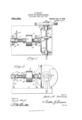
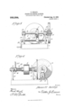
- Figure 1 is a plan view of a grinding machine embodying the resent invention.
- Fig. 2 is an elevation loo ring toward the inner side ofthe grinding wheel.
- Fig. 3 is a view taken at right angles to Fig. 2 looking toward the edge of the grinding wheel, the latter being partly broken away.
- Fig. 4 is a vertical sectional view of the machine, showing the manner of mounting and shifting the main drive shaft.
- the machine comprises essentially a suitable base 1 provided with upstanding posts 2 which carry bearings 3 for the main drive shaft 4, the latter being provided with a band wheel 5 by means of which the shaft 4 is driven from any suitable source of power.
- a friction disk 6 mounted on one end'of the shaft 4 is a friction disk 6 of any suitable size which is adapted to engage and drive a similar fric tion wheel 7 fast on a grinding wheel shaft 8, upon one end of which the grinding wheel 9 is fastened, said grinding wheel being made removable from the shaft'by providing said shaft with a fixed collar or shoulder 10, a removable clamping collar 11 and a clamping nut 12 or other retaining means for the collar 11.
- the shaft 8 is mounted in bearings 13 on the upper end of posts 14 secured to and extendingupward from the base 1.
- a throw-off spring 15 which is of spiral form surrounding the shaft 4 and acting ex ansively to ress the wheel 5 away from t e adjacent earing 3 and thereby moving the friction wheel 6 in a corresponding direction away from the periphery of the friction wheel 7.
- the shaft 4 is shifted lengthwise in the direction of the shaft 8 by means of a shipper cam 16 having a plurality of inclined faces 17 which cooperate with lugs or shoulders 18 on the outer end bearing 3 above referred to.
- the ship er cam is also provided with one or more locff notches 19 adapted to be engaged by the pointed extremity of one of the lugs 18 as shown in Fig. 2, whereby said. collar is locked in position when the shaft 4 is urged toward the shaft 8.
- a spring Interposed between the shipper cam 16 and a collar 20 on the shaft 4 is a spring, the tension of which is exerted to hold the friction wheels 6 and 7 constantly in driving engagement with each other.
- the collar 20 is made adjustable on the shaft by means of a set screw 22, whereby the tension of the spring 21 may be adjusted so as to correspondingly vary the pressure of the disk 6 against the wheel 7.
- the shipper cam 16 is provided with an operating handle 23 so that said shipper cam may be turned in one direction or the other and when said cam is turned'in one direction it tends to throw the disk 6 against the wheel 7 while when said cam is thrown in the opposite direction, it allows the throw-off spring 10 to move the disk 6 away from the wheel 7.
- the shaft 8 is provided with a longitudinal key-way 24 while the friction wheel 7 is provided with a hub 25 carrying a key 26 which works in the way 24.
- I employ a runner 27 having fork arms 28 which embrace the friction wheel and its hub as shown in Fig. 3 for the purpose of shifting said wheel along the shaft 8.
- the runner is provided with a threaded opening to receive a feed screw 29 which is journaled in bearings on the posts 14 and provided at oneend with an operating crank 1andle-3O by the turning of which the runner 27 may be fed lengthwise of the feed screw, thereby shifting the wheel 7 across the face of the friction disks 6.
- the wheel 7 may be speed s ifted past the center of the disk 6 for the purpose of reversing the direction of rotation of the shaft 8 and varying the speed of said shaft in both directions for the purpose of obtaining a given rate of speed for the periphery or grinding surface of the abrasive wheel 9.
- I claim v The combination with a rotary longitudinally shiftable driving shaft having a uniform speed, and a rotary driven shaft of variable speed, of variable speed gearing connecting said shafts and embodying a friction disk on the driving shaft, a friction wheel on the driven shaft shiftable across the face of the friction disk, and means for moving the driving shaft lengthwise embodying a throwoff spring acting to urge the disk away from the friction wheel, a eounteractingspring operating to urge the disk toward the friction Wheel, a shipper cam ournaled on the driving shaft and adapted to urge said shaft toward the friction wheel, and a fixed lug against which the cam works with which it is adapted to interlock to hold said disk and friction Wheel in operative contact.
Landscapes
- Engineering & Computer Science (AREA)
- General Engineering & Computer Science (AREA)
- Mechanical Engineering (AREA)
- Constituent Portions Of Griding Lathes, Driving, Sensing And Control (AREA)
Description
11. KELLEY. GEARING FOR GRINDING MACHINES.
APPLICATION FILED JUNE 12, 1908. 930,384 Patented Aug. 10, 1909. EEET 1.
anon Wow D. KELLEY.
GEARING FOB GRINDING MACHINES.
APPLICATION FILED JUNE 12, 1908.
930,384. Patented Aug. 10,1909.
2 SHEETS-SHEET 2.
wit" men abtomwa DEWITT KELLEY, OF WARREN, PENNSYLVANIA.
GEARING FOR GRINDING-MACHINES.
Specification of Letters Patent.
Patented Aug. 10, 1909.
Application fi led. June 12, 1908. Serial No. 438,171.
To all whom it may concern:
Be it known that I, DEWITT KELLEY, a citizen of the United States, residing at Warren, in the county of Warren and State of Pennsylvania, have invented new and useful Improvements in Gearing for Grinding-Machines, of which the following is a specificatlon.
This invention relates to grinding machines, the object of the same being to provide a machine by means of which a grinding wheel of any desired size may be driven at a speed which will give to the peripheral or grinding surface of the wheel a certain predetermined speed, irrespective of' the speed at which the driving shaft of themachine is driven. In order to obtain the best results it is necessary to' have a certain surface speed at the grinding surface of the emery or other wheel and as this is ordinarily impossible with the usual grinding machines, the aim of the present invention is to provide simple means for accomplishing the result stated and also for reversing the direction of rotation of the grinding wheel at the same time regulating the speed at which said wheel is driven in the other direction.
With the above and other objects in view,
the nature of which will more fully appear as the description proceeds, the invention consists in the novel construction, combination and arrangement of parts as herein fully described, illustrated and claimed.
In the accompanying drawings :Figure 1 is a plan view of a grinding machine embodying the resent invention. Fig. 2 is an elevation loo ring toward the inner side ofthe grinding wheel. Fig. 3 is a view taken at right angles to Fig. 2 looking toward the edge of the grinding wheel, the latter being partly broken away. Fig. 4 is a vertical sectional view of the machine, showing the manner of mounting and shifting the main drive shaft.
The machine comprises essentially a suitable base 1 provided with upstanding posts 2 which carry bearings 3 for the main drive shaft 4, the latter being provided with a band wheel 5 by means of which the shaft 4 is driven from any suitable source of power.
Mounted on one end'of the shaft 4 is a friction disk 6 of any suitable size which is adapted to engage and drive a similar fric tion wheel 7 fast on a grinding wheel shaft 8, upon one end of which the grinding wheel 9 is fastened, said grinding wheel being made removable from the shaft'by providing said shaft with a fixed collar or shoulder 10, a removable clamping collar 11 and a clamping nut 12 or other retaining means for the collar 11. The shaft 8 is mounted in bearings 13 on the upper end of posts 14 secured to and extendingupward from the base 1.
Between one of the bearings 3 and the adjacent side of the band wheel 5 there is arranged a throw-off spring 15 which is of spiral form surrounding the shaft 4 and acting ex ansively to ress the wheel 5 away from t e adjacent earing 3 and thereby moving the friction wheel 6 in a corresponding direction away from the periphery of the friction wheel 7.
In order to throw the friction disk into operative engagement with the friction wheel 7, the shaft 4 is shifted lengthwise in the direction of the shaft 8 by means of a shipper cam 16 having a plurality of inclined faces 17 which cooperate with lugs or shoulders 18 on the outer end bearing 3 above referred to. The ship er cam is also provided with one or more locff notches 19 adapted to be engaged by the pointed extremity of one of the lugs 18 as shown in Fig. 2, whereby said. collar is locked in position when the shaft 4 is urged toward the shaft 8. Interposed between the shipper cam 16 and a collar 20 on the shaft 4 is a spring, the tension of which is exerted to hold the friction wheels 6 and 7 constantly in driving engagement with each other. The collar 20 is made adjustable on the shaft by means of a set screw 22, whereby the tension of the spring 21 may be adjusted so as to correspondingly vary the pressure of the disk 6 against the wheel 7. The shipper cam 16 is provided with an operating handle 23 so that said shipper cam may be turned in one direction or the other and when said cam is turned'in one direction it tends to throw the disk 6 against the wheel 7 while when said cam is thrown in the opposite direction, it allows the throw-off spring 10 to move the disk 6 away from the wheel 7.
The shaft 8 is provided with a longitudinal key-way 24 while the friction wheel 7 is provided with a hub 25 carrying a key 26 which works in the way 24. In connection with the hub and body of the friction wheel 7, I employ a runner 27 having fork arms 28 which embrace the friction wheel and its hub as shown in Fig. 3 for the purpose of shifting said wheel along the shaft 8. The runner is provided with a threaded opening to receive a feed screw 29 which is journaled in bearings on the posts 14 and provided at oneend with an operating crank 1andle-3O by the turning of which the runner 27 may be fed lengthwise of the feed screw, thereby shifting the wheel 7 across the face of the friction disks 6. This provides for changing the speed of the shaft 8 relatively to the shaft 4, the latter being continuously driven at the same rate of Furthermore, the wheel 7 may be speed s ifted past the center of the disk 6 for the purpose of reversing the direction of rotation of the shaft 8 and varying the speed of said shaft in both directions for the purpose of obtaining a given rate of speed for the periphery or grinding surface of the abrasive wheel 9.
I claim v The combination with a rotary longitudinally shiftable driving shaft having a uniform speed, and a rotary driven shaft of variable speed, of variable speed gearing connecting said shafts and embodying a friction disk on the driving shaft, a friction wheel on the driven shaft shiftable across the face of the friction disk, and means for moving the driving shaft lengthwise embodying a throwoff spring acting to urge the disk away from the friction wheel, a eounteractingspring operating to urge the disk toward the friction Wheel, a shipper cam ournaled on the driving shaft and adapted to urge said shaft toward the friction wheel, and a fixed lug against which the cam works with which it is adapted to interlock to hold said disk and friction Wheel in operative contact.
In testimony whereof I affix my signature in presence of two witnesses.
DEWITT KELLEY.
Witnesses B. 8. DE FREEs, H. S. AYERS.
Priority Applications (1)
| Application Number | Priority Date | Filing Date | Title |
|---|---|---|---|
| US43817108A US930384A (en) | 1908-06-12 | 1908-06-12 | Gearing for grinding-machines. |
Applications Claiming Priority (1)
| Application Number | Priority Date | Filing Date | Title |
|---|---|---|---|
| US43817108A US930384A (en) | 1908-06-12 | 1908-06-12 | Gearing for grinding-machines. |
Publications (1)
| Publication Number | Publication Date |
|---|---|
| US930384A true US930384A (en) | 1909-08-10 |
Family
ID=2998807
Family Applications (1)
| Application Number | Title | Priority Date | Filing Date |
|---|---|---|---|
| US43817108A Expired - Lifetime US930384A (en) | 1908-06-12 | 1908-06-12 | Gearing for grinding-machines. |
Country Status (1)
| Country | Link |
|---|---|
| US (1) | US930384A (en) |
Cited By (1)
| Publication number | Priority date | Publication date | Assignee | Title |
|---|---|---|---|---|
| US3934670A (en) * | 1974-02-25 | 1976-01-27 | Thord Erik Medalen | Vehicle for propulsion of gardening implements and the like |
-
1908
- 1908-06-12 US US43817108A patent/US930384A/en not_active Expired - Lifetime
Cited By (1)
| Publication number | Priority date | Publication date | Assignee | Title |
|---|---|---|---|---|
| US3934670A (en) * | 1974-02-25 | 1976-01-27 | Thord Erik Medalen | Vehicle for propulsion of gardening implements and the like |
Similar Documents
| Publication | Publication Date | Title |
|---|---|---|
| US1192627A (en) | Speed-reducer. | |
| US760460A (en) | Variable-speed gear. | |
| US521677A (en) | Island | |
| US706265A (en) | Means for securing wheels on shafts. | |
| US483288A (en) | Grinding-machine | |
| US488390A (en) | Driving-pulley | |
| US401018A (en) | Frictional gearing | |
| US761384A (en) | Friction-gearing. | |
| US423864A (en) | Drilling-machine | |
| US597311A (en) | George busch | |
| US186304A (en) | Improvement in friction-wheels | |
| US460884A (en) | Half to james jenkins | |
| US520626A (en) | Mechanical movement | |
| US1336863A (en) | Valve-grinder | |
| US507496A (en) | Sylvania | |
| US944872A (en) | Transmission-gearing. | |
| US704245A (en) | Means for transmitting rotary motion. | |
| US622160A (en) | Friction driving device for shaping or other machines | |
| US205904A (en) | Improvement in sewing-machines | |
| US2737821A (en) | Frictional driving mechanisms | |
| US782481A (en) | Friction-clutch power-transmitter. | |
| US773240A (en) | Driving connection for metal-planing machines. | |
| US696849A (en) | Reversing and variable-speed gearing. | |
| US587383A (en) | Roll-grinding machine | |
| US637202A (en) | Motion-reversing and speed-changing mechanism. |