US9298430B2 - Method of compiling program to be executed on multi-core processor, and task mapping method and task scheduling method of reconfigurable processor - Google Patents
Method of compiling program to be executed on multi-core processor, and task mapping method and task scheduling method of reconfigurable processor Download PDFInfo
- Publication number
- US9298430B2 US9298430B2 US14/051,910 US201314051910A US9298430B2 US 9298430 B2 US9298430 B2 US 9298430B2 US 201314051910 A US201314051910 A US 201314051910A US 9298430 B2 US9298430 B2 US 9298430B2
- Authority
- US
- United States
- Prior art keywords
- task
- communication scheme
- mapping
- destination
- scheduling
- Prior art date
- Legal status (The legal status is an assumption and is not a legal conclusion. Google has not performed a legal analysis and makes no representation as to the accuracy of the status listed.)
- Active, expires
Links
Images


Classifications
-
- G—PHYSICS
- G06—COMPUTING OR CALCULATING; COUNTING
- G06F—ELECTRIC DIGITAL DATA PROCESSING
- G06F8/00—Arrangements for software engineering
- G06F8/40—Transformation of program code
-
- G—PHYSICS
- G06—COMPUTING OR CALCULATING; COUNTING
- G06F—ELECTRIC DIGITAL DATA PROCESSING
- G06F8/00—Arrangements for software engineering
- G06F8/40—Transformation of program code
- G06F8/41—Compilation
-
- G—PHYSICS
- G06—COMPUTING OR CALCULATING; COUNTING
- G06F—ELECTRIC DIGITAL DATA PROCESSING
- G06F8/00—Arrangements for software engineering
- G06F8/40—Transformation of program code
- G06F8/41—Compilation
- G06F8/45—Exploiting coarse grain parallelism in compilation, i.e. parallelism between groups of instructions
-
- G—PHYSICS
- G06—COMPUTING OR CALCULATING; COUNTING
- G06F—ELECTRIC DIGITAL DATA PROCESSING
- G06F9/00—Arrangements for program control, e.g. control units
- G06F9/06—Arrangements for program control, e.g. control units using stored programs, i.e. using an internal store of processing equipment to receive or retain programs
- G06F9/46—Multiprogramming arrangements
Definitions
- Apparatuses and methods consistent with the following description relate to a method for compiling a program to be executed on a multi-core processor, and task mapping and task scheduling of the multi-core processor.
- Comparable programming for characteristics of a multicore architecture may improve the performance of multicore architecture.
- mapping refers to a process of determining which processing elements to execute in terms of the tasks or individual parts of an application and representing the determination as a graph.
- scheduling is a process that may follow the mapping process. Scheduling may determine an order and timing according to which the respective tasks are executed by the processing elements.
- a multicore program executed on a multicore is so highly complex that manual writing of the program results in low programming productivity and/or low program quality. Further, the complexity of programming may be increased by the mapping and scheduling processes.
- a method of compiling a program to be executed on a multicore processor including: generating an initial solution by mapping a task to a source processing element (PE) and a destination PE, and selecting a communication scheme for transmission of the task from the source PE to the destination PE; approximately optimizing the mapping and communication scheme included in the initial solution; and scheduling the task, wherein the communication scheme is designated in a compiling process.
- PE source processing element
- a method of mapping a task in a multi-core processor including: mapping the task to a first processing element from among multiple processing elements in the multi-core processor; moving the task from the first processing element to a second processing element at a first probability between 0 and 1; and replacing the task that has been moved to the second processing element at the first probability with another task mapped to a third processing element at a second probability between 0 and 1.
- a method of scheduling tasks in a multi-core processor including: attempting to schedule two or more tasks within a first time period wherein the two or more tasks are to be executed on two or more processing elements of a multi-core processor; if the scheduling attempt fails due to one task overlapping another task, calculating a length of time during which the tasks are overlapping each other; and re-attempting to schedule the two or more tasks within a second time period which is equal to a sum of the first time period and the calculated length of time for which the tasks are overlapping.
- FIGS. 1A and 1B are diagrams illustrating processing elements of a multicore processor, which communicate with each other using a shared memory;
- FIGS. 2A and 2B are diagrams illustrating processing elements of a multicore processor, which communicate with each other by passing messages;
- FIG. 3 is a flowchart illustrating a method of mapping tasks and determining a communication scheme according to an exemplary embodiment
- FIG. 4 is a diagram illustrating in detail a step of changing an initial solution according to an exemplary embodiment
- FIG. 5 is a diagram illustrating a case in which tasks are switched between processing elements at a probability of ⁇ according to an exemplary embodiment
- FIG. 6 is a diagram illustrating a case in which a task is moved from one processing element to another processing element at a probability of (1 ⁇ ) according to an exemplary embodiment
- FIG. 7 is a flowchart illustrating an optimization process according to an exemplary embodiment
- FIG. 8 is a flowchart illustrating an instruction scheduling operation using a modulo algorithm according to an exemplary embodiment
- FIG. 9 is a flowchart illustrating task scheduling operation using a modified modulo algorithm according to an exemplary embodiment
- FIG. 10 is a flowchart illustrating a method of compiling a program to be executed on a reconfigurable processor according to an exemplary embodiment
- FIG. 11 is a flowchart illustrating a method of compiling a program to be executed on a reconfigurable processor according to an exemplary embodiment
- FIG. 12 is a flowchart illustrating a task mapping method performed by a reconfigurable processor according to an exemplary embodiment
- FIG. 13 is a flowchart illustrating a task scheduling method performed by a reconfigurable processor according to an exemplary embodiment.
- FIGS. 1A and 1B are diagrams illustrating processing elements of a multicore processor, which may communicate with each other using a shared memory 120 .
- FIGS. 1A and 1B the same reference numerals represent the same elements.
- Processing elements (PEs) 112 a and 112 b of a multicore processor may communicate with each other. Referring to FIGS. 1A and 1B , the processing elements communicate with each other with the help of and through the shared memory 120 .
- the communication via the shared memory may be performed in stages, as follows:
- a source PE 112 A may writes data to the shared memory 120 .
- the shared memory 120 transmits an acknowledgement (ACK) to the source PE 112 a.
- ACK acknowledgement
- the source PE 112 a may transmit a synchronization (SYNC) packet to a destination PE 112 b.
- SYNC synchronization
- the destination PE 112 b may then transmit a read request to the shared memory 120 .
- the shared memory 120 may transmit the data stored by the PE 112 a to the destination PE 112 b.
- This method may be easy to program and facilitate multitasking.
- a long path from the processing element 112 a to the shared memory 120 (labeled in FIG. 1B as “path(shared memory)”) may frequently occur.
- the shared memory 120 in use may also have a large size and a slow operation speed. Further, there may exist drawbacks such as large power consumption and slow task execution speeds.
- FIGS. 2A and 2B are diagrams illustrating processing elements 112 a and 112 b of a multicore processor, which may communicate with each other by transmitting messages.
- processing elements (PEs) 112 a and 112 b may communicate with each other using a scratch-pad memory (SPM) that may be disposed in or near each processing element.
- SPM scratch-pad memory
- a source PE 112 a may therefore directly transmit data to a destination PE 112 b , rather than having to write the data to a shared memory 120 , which is commonly used by all processing elements of the multicore processor.
- the data may be transmitted through the shortest path (illustrated in FIG.
- path(SPM) from the source PE 112 a to the destination PE 112 b , and thus transmission time can be reduced, as compared to the path (“path(shared memory”) shown in FIG. 1B , which routes to and from the shared memory 120 .
- path(shared memory) shown in FIG. 1B , which routes to and from the shared memory 120 .
- an SPM may have a comparatively small capacity compared to a shared memory. Therefore, data transmission, called a “message passing method,” using an SPM may have the advantage of lower power consumption.
- the benefits obtained from the application of the message passing method may vary depending on diverse factors, such as, a distance between two computers. Therefore, it may be proper to select a particular communication scheme between the shared memory-based communication scheme and the message passing-based communication scheme, during the mapping and/or scheduling processes.
- FIG. 3 is a flowchart illustrating a method of mapping tasks and determining a communication scheme according to an exemplary embodiment.
- task scheduling tasks are assigned to processing elements and a particular communication scheme is determined for transmission of each task between a source PE and a destination PE.
- the method illustrated in FIG. 3 may be based on a simulated annealing (SA) algorithm that is a probabilistic algorithm.
- SA simulated annealing
- the new solution is better than the initial solution, replace the initial solution with the new solution, and if not, replace the initial solution with the new solution according to a predetermined probability r (r is greater than 0 and smaller than 1).
- the SA algorithm can achieve a better solution than a local search algorithm.
- the method shown in FIG. 3 may include two steps: generation of an initial solution (S 100 ) and change of the initial solution (S 110 ).
- Each solution may include a task mapping state with respect to each PE and a particular communication scheme for transmission of each task between a source PE and a destination PE.
- a new solution may be created by changing the task mapping state and communication scheme for each task.
- FIG. 4 is a diagram illustrating in detail an operation step of changing an initial solution, similar to operation S 110 of FIG. 3 , according to an exemplary embodiment.
- Operation S 110 may include task moving operation S 112 and communication scheme changing operation S 114 .
- a task is moved to another PE with respect to the task mapped to a particular PE in the initial solution.
- the task may be moved from the particular PE to another PE at a probability of a in S 1120 .
- ⁇ is a value between 0 and 1.
- a probability of the task not moving is (1 ⁇ ) in S 1130 .
- the task moving to the other PE may be switched with another task of a different PE at a probability of ⁇ in S 1121 .
- ⁇ is a value between 0 and 1.
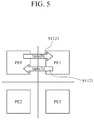
- FIG. 5 is a diagram illustrating a case in which tasks are switched between processing elements at a probability of ⁇ according to an exemplary embodiment.
- task 0 is mapped to processing element PE0 and task 1 is mapped to processing element PE1.
- the task 1 mapped to PE0 is moved to PE1 and the task 0 mapped to PE1 is moved to PE0 at a probability of ⁇ .
- the task mapped to PE0 may be moved to yet another PE (PE2) at a probability of (1 ⁇ ).
- FIG. 6 is a diagram illustrating a case in which a task is moved from one processing element to another processing element at a probability of (1 ⁇ ).
- a current communication scheme may be changed to another communication scheme at a probability of ⁇ in S 1110 , S 1142 , and S 1144 .
- a probability of changing the communication scheme using a shared memory is ⁇ .
- ⁇ is a value between 0 and 1.
- the particular communication scheme may not be changed to another scheme at a probability of (1 ⁇ ) in S 1141 , S 1143 , and S 1145 .
- optimization may need to be additionally performed on the changed solution.
- a gain obtained from the use of the message passing-based communication scheme instead of a shared memory-based communication scheme, may vary depending on various factors, such as a communication distance between PEs, communication data traffic, or usage rate of SPM, etc. Therefore, it may be appropriate to preferentially apply the message passing-based communication scheme to a task that brings about more advantages from the message passing-based communication scheme than from the shared memory-based communication scheme.
- a gain G(t) with respect to a task t between a source PE and a destination PE may be represented as equation (1) below.
- G ( t ) ( L ⁇ A )/ T (1),
- L represents a communication distance between a source PE and a destination PE
- A represents data traffic between the source PE and the destination PE
- B is the sum of SPM usage.
- Heuristics more specifically, a greedy algorithm heuristic may be used for an optimization process.
- the optimization process following the changing (S 110 ) of the initial solution can be considered as heuristic optimization.
- FIG. 7 is a flowchart illustrating an optimization process according to an exemplary embodiment.
- the optimization process includes the stages of: violation elimination (S 200 ) and utilization enhancement (S 210 ).
- violation may be eliminated from mapping and/or communication schemes for each task included in the changed initial solution obtained in operation S 110 .
- the mapping and communication schemes for each task which are included in the solution obtained after operation S 110 (change of the initial solution), may likely be associated with PEs transmitting data with sizes exceeding sizes of SPMs (hereinafter, the PEs are referred to as “violating” PEs).
- the violation of the violating PEs may be eliminated.
- the violating PEs are arranged in the order of data size that exceeds the size of SPM. Then, the message passing-based communication scheme designated to each task mapped to the arranged violating processing element(s) is changed to a shared memory-based communication scheme, until the violation is overcome (that is, until the data size of each violating PE does not exceed the size of SPM).
- the communication scheme may be sequentially changed, starting from the task with the lowest gain which is obtained by Equation 1.
- some PEs may have SPM with unused space that may be an excessively large. This may be because of either the initial solution or the change of the communication scheme of the task that requires a large memory capacity to the shared memory-based communication scheme in the violation elimination process.
- the PEs containing SPM with unused space may be arranged in the order of an amount of the unused space of SPM. Then, the shared memory-based communication scheme that is designated for each task assigned to the arranged PEs is changed to the message passing-based communication scheme.
- mapping is involved with how to determine PEs to which tasks are assigned
- scheduling is a process to determine timing at which to execute each assigned task.
- Modulo algorithm is a type of priority-based scheduling algorithm. Modulo algorithm estimates an initiation interval (II) which refers to a time interval between cycles of iterations, and then attempts to schedule all tasks within the estimated time interval. If the attempt to schedule the tasks fails, the iteration interval is gradually raised until an optimized II is found.
- II initiation interval
- FIG. 8 is a flowchart illustrating an instruction scheduling operation using a modulo algorithm according to an exemplary embodiment.
- the modulo algorithm is an algorithm suited for scheduling instructions. For example, an iteration interval of a routine that is to be iteratively executed is assigned within the initiation interval (II) in operation S 300 . A condition may be applied such that scheduling is performed within a predetermined time period t in operation S 310 . The scheduling is repeatedly attempted in operation S 320 with the conditions of the iteration interval and the time period. When the scheduling attempt fails, the instruction scheduling attempts are made by increasing the time period by 1 (or unit time) in operation S 350 .
- the initiation interval may be re-set to II+1 by increasing the initiation interval by 1 (or “unit time”) in operation S 360 .
- the scheduling attempt starts from the predetermined time period (t).
- this method may be appropriate for scheduling instructions, it may not be as conducive for task scheduling because it may take excessively large amounts of time to schedule tasks by using this method. Hence, the algorithm that is to be used for instruction scheduling may not be used in task scheduling.
- FIG. 9 is a flowchart illustrating a task scheduling operation using a modified modulo algorithm according to an exemplary embodiment.
- an iteration interval is assigned within an initiation interval, so as to schedule tasks with iteratively executed routines.
- conditions are applied such that the scheduling is performed within a predetermined time period (t).
- scheduling attempts are repeatedly made under the conditions of the iteration interval and the predetermined time period. When the scheduling attempt fails, scheduling is re-attempted in operation S 450 .
- operation S 432 In the event of a failure of scheduling due to a particular task (task (a)) overlapping another task (task (b)), in operation S 432 , it calculates a length t overlap of a time period during which the tasks are overlapping.
- the modified modulo algorithm differs from the general modulo algorithm in this respect.
- operation S 450 a new time period (t+t overlap ) is set and the scheduling is attempted again within the new time period.
- the modified modulo algorithm is different from the general modulo algorithm that increases the time period by a unit time (e.g., “1”) and re-attempts the scheduling within the new time period.
- the iteration interval may be re-set by increasing the II in operation S 460 . In this case, the scheduling attempts are made again, starting from the predetermined time period (t).
- the modified modulo algorithm calculates a minimum value (i.e., min(t overlap )) of the length t overlap of overlapping time period which is obtained based on the initiation interval (II) just before the re-setting of the iteration interval.
- a minimum value i.e., min(t overlap )
- the modified modulo algorithm calculates a minimum value (i.e., min(t overlap )) of the length t overlap of overlapping time period which is obtained based on the initiation interval (II) just before the re-setting of the iteration interval.
- an attempt to schedule a task with the II set to II+min(t overlap ) is made. That is, the modified modulo algorithm is different from the general modulo algorithm in that the initiation interval (II) is increased by a unit time (e.g., “1”) and scheduling attempt is made again with the new initiation interval (II).
- the execution time of task scheduling may be remarkably reduced when using the modified modulo algorithm, as compared to when using the general modulo algorithm. This is because, if the same number of re-attempts of scheduling are made, the modified modulo algorithm can make scheduling attempts with a time period that is longer than a time period set by the general modulo algorithm because t overlap and min (t overlap ) are each longer than a unit time.
- the scheduling result of the modified modulo algorithm is not substantially lowered, as compared to the scheduling result of the general modulo algorithm.
- FIG. 10 is a flowchart illustrating a method of compiling a program to be executed on a reconfigurable processor according to an exemplary embodiment.
- the compiling method includes operations that include the generation of an initial solution (S 500 ), performing approximate optimization (S 510 ), and scheduling tasks (S 520 ).
- an initial solution is generated as described above, such that a number of tasks are mapped to a plurality of processing elements using a probabilistic algorithm and a particular communication scheme for each task to be transmitted between a source processing element and a destination processing element is designated.
- a probabilistic algorithm For example, a simulated annealing (SA) algorithm may be used as the probabilistic algorithm.
- the particular communication scheme may be selected between a shared memory-based communication scheme and a scratch pad memory (SPM) utilizing message passing-based communication scheme. Reassignment of each task mapped to the processing element according to the initial solution and/or change of the communication scheme designated for each task may be performed on the basis of probabilities for each scheme.
- mapping and communication schemes included in the initial solution are approximately optimized.
- the approximate optimization may use heuristic as described above.
- an optimization process may be performed to eliminate violation, such that the sum of sizes of data related to a task mapped to a particular processing element does not exceed the capacity of SPM.
- the shared memory-based communication scheme designated to a task mapped to a processing element containing SPM with unused space is changed to a message passing-based communication scheme to enhance the degree of utilization of SPM.
- Task scheduling may be performed by repeatedly performing the following operations: attempting to schedule the tasks within a predetermined time period, and when the scheduling attempt fails, calculating a length of a time period during which tasks are overlapping, then reattempting to schedule the tasks within a new time period that is obtained by adding the predetermined time period and the calculated overlapping time period.
- FIG. 11 is a flowchart illustrating a method of compiling a program to be executed on a reconfigurable processor according to an exemplary embodiment.
- Operations S 600 , S 610 and S 620 are substantially similar to operations S 500 , S 510 and S 520 of FIG. 10 , respectively.
- the compiling method of FIG. 11 further includes evaluating (S 630 ) of a scheduling result after the scheduling operation S 620 . Based on the evaluation result from operation S 630 , a new solution that is better than an initial solution obtained in operation S 600 is generated in operation S 640 , and an approximate optimization operation S 610 and the following operations are performed on the new solution.
- FIG. 12 is a flowchart illustrating a task mapping method performed by a reconfigurable processor according to an exemplary embodiment.
- the task mapping method includes the operations of a relocating of tasks (S 700 ) and a changing of communication scheme (S 710 ).
- a task mapped to one of multiple processing elements of a multicore processor is moved to another processing element at a first probability ranging between 0 and 1.
- the task that has been moved to the other processing element at the first probability may be switched with a task mapped to a different processing element, at a second probability ranging between 0 and 1.
- a communication scheme for each task to be transmitted between a source PE and a destination PE is changed at a third probability ranging between 0 and 1.
- mapping results may be achieved.
- FIG. 13 is a flowchart illustrating a task scheduling method performed by a reconfigurable processor according to another exemplary embodiment.
- the task scheduling method includes operations of attempting to schedule tasks (S 800 ), calculating a length of an overlapping time period (S 810 ), calculating an iteration interval (S 820 ), and reattempting the scheduling (S 830 ).
- a length of a time period during which the tasks are overlapping is calculated operation S 810 . Then, a second time period is obtained by adding the first time period S 820 and the calculated length of the overlapping time period and a new attempt to schedule the tasks with the second time period is made operation S 830 .
- the task scheduling method of FIG. 13 may be applied to cyclic routines that are iteratively executed. Hence, if at least a part of a task is iteratively executed at a first iteration interval, a minimum value of an overlapping time period is obtained and a new iteration interval is set in operation S 820 by adding the current iteration interval and the obtained minimum value. Then, scheduling attempts are repeatedly made under the conditions of a second iteration interval and a second time period in operation S 830 .
- the current embodiments can be implemented as computer readable codes in a computer readable record medium. Codes and code segments constituting the computer program can be easily inferred by a skilled computer programmer in the art.
- the computer readable record medium includes all types of record media in which computer readable data are stored. Examples of the computer readable record medium include a ROM, a RAM, a CD-ROM, a magnetic tape, a floppy disk, and an optical data storage. Further, the record medium may be implemented in the form of a carrier wave such as Internet transmission. In addition, the computer readable record medium may be distributed to computer systems over a network, in which computer readable codes may be stored and executed in a distributed manner.
Landscapes
- Engineering & Computer Science (AREA)
- Theoretical Computer Science (AREA)
- General Engineering & Computer Science (AREA)
- Software Systems (AREA)
- Physics & Mathematics (AREA)
- General Physics & Mathematics (AREA)
- Devices For Executing Special Programs (AREA)
Abstract
Description
G(t)=(L×A)/T (1),
Claims (24)
Applications Claiming Priority (2)
| Application Number | Priority Date | Filing Date | Title |
|---|---|---|---|
| KR1020120113103A KR101926464B1 (en) | 2012-10-11 | 2012-10-11 | Method for compiling program running on multi-core processor, task mapping method of multi-core processor and task scheduling method of reconfigurable processor |
| KR10-2012-0113103 | 2012-10-11 |
Publications (2)
| Publication Number | Publication Date |
|---|---|
| US20140109069A1 US20140109069A1 (en) | 2014-04-17 |
| US9298430B2 true US9298430B2 (en) | 2016-03-29 |
Family
ID=49382262
Family Applications (1)
| Application Number | Title | Priority Date | Filing Date |
|---|---|---|---|
| US14/051,910 Active 2034-04-15 US9298430B2 (en) | 2012-10-11 | 2013-10-11 | Method of compiling program to be executed on multi-core processor, and task mapping method and task scheduling method of reconfigurable processor |
Country Status (5)
| Country | Link |
|---|---|
| US (1) | US9298430B2 (en) |
| EP (1) | EP2720147B1 (en) |
| JP (1) | JP6291209B2 (en) |
| KR (1) | KR101926464B1 (en) |
| CN (1) | CN103729228B (en) |
Families Citing this family (8)
| Publication number | Priority date | Publication date | Assignee | Title |
|---|---|---|---|---|
| CN104641352B (en) * | 2012-08-02 | 2018-06-29 | 西门子公司 | For the pile line operation of cycle control system |
| CN103995744B (en) * | 2014-05-22 | 2017-04-26 | 西安交通大学 | Isomorphic calculation task grouping method used for eliminating memory access congestion |
| CN104572266B (en) * | 2015-01-04 | 2018-03-06 | 华东师范大学 | MPSoC task schedulings modeling based on UPPAAL SMC and appraisal procedure under process variation |
| CN107291548B (en) * | 2016-03-31 | 2021-04-13 | 阿里巴巴集团控股有限公司 | Task resource scheduling method and device |
| US11836547B2 (en) | 2017-09-27 | 2023-12-05 | Hitachi Astemo, Ltd. | Data transmission device including shared memory having exclusive bank memories for writing and reading |
| CN108108237B (en) * | 2017-12-27 | 2021-09-28 | 电子科技大学 | MILP-based heterogeneous multi-core mapping scheduling method for periodic associated tasks |
| US11128531B2 (en) * | 2018-04-30 | 2021-09-21 | Hewlett Packard Enterprise Development Lp | Systems and methods for aggregate bandwidth and latency optimization |
| CN110514982B (en) * | 2019-08-22 | 2022-03-22 | 上海兆芯集成电路有限公司 | Performance Analysis System and Method |
Citations (7)
| Publication number | Priority date | Publication date | Assignee | Title |
|---|---|---|---|---|
| CA2275826A1 (en) | 1999-06-18 | 2000-12-18 | Jia Xu | A method of scheduling executions of periodic and asynchronous real-time processes having hard or soft deadlines |
| US20060161755A1 (en) * | 2005-01-20 | 2006-07-20 | Toshiba America Electronic Components | Systems and methods for evaluation and re-allocation of local memory space |
| US20090213755A1 (en) | 2008-02-26 | 2009-08-27 | Yinghai Lu | Method for establishing a routing map in a computer system including multiple processing nodes |
| US20100218190A1 (en) | 2009-02-23 | 2010-08-26 | International Business Machines Corporation | Process mapping in parallel computing |
| US20100293312A1 (en) | 2009-04-27 | 2010-11-18 | Sonnier David P | Network Communications Processor Architecture |
| US8020163B2 (en) | 2003-06-02 | 2011-09-13 | Interuniversitair Microelektronica Centrum (Imec) | Heterogeneous multiprocessor network on chip devices, methods and operating systems for control thereof |
| US20120144401A1 (en) * | 2010-12-03 | 2012-06-07 | International Business Machines Corporation | Data Communications For A Collective Operation In A Parallel Active Messaging Interface Of A Parallel Computer |
Family Cites Families (12)
| Publication number | Priority date | Publication date | Assignee | Title |
|---|---|---|---|---|
| JP3364274B2 (en) * | 1993-05-21 | 2003-01-08 | 松下電器産業株式会社 | Task assignment device |
| JP3016359B2 (en) * | 1995-07-21 | 2000-03-06 | 日本電気株式会社 | Processor allocation device, processor allocation method, and medium storing processor allocation program in multiprocessor system |
| US7564847B2 (en) * | 2004-12-13 | 2009-07-21 | Intel Corporation | Flow assignment |
| US8826228B2 (en) * | 2006-03-27 | 2014-09-02 | Coherent Logix, Incorporated | Programming a multi-processor system |
| CN101165655A (en) * | 2006-10-20 | 2008-04-23 | 国际商业机器公司 | Multiple processor computation system and its task distribution method |
| JP2007188523A (en) * | 2007-03-15 | 2007-07-26 | Toshiba Corp | Task execution method and multiprocessor system |
| WO2010004474A2 (en) * | 2008-07-10 | 2010-01-14 | Rocketic Technologies Ltd | Efficient parallel computation of dependency problems |
| CN101620526B (en) * | 2009-07-03 | 2011-06-15 | 中国人民解放军国防科学技术大学 | Method for reducing resource consumption of instruction memory on stream processor chip |
| KR101612780B1 (en) * | 2009-11-13 | 2016-04-18 | 삼성전자주식회사 | Computing system and method for controling memory of computing system |
| KR101565172B1 (en) * | 2010-01-15 | 2015-11-02 | 삼성전자주식회사 | Apparatus and method for processing data of massively parallel processor array system |
| KR101647817B1 (en) * | 2010-03-31 | 2016-08-24 | 삼성전자주식회사 | Apparatus and method for simulating reconfigrable processor |
| CN102087609B (en) * | 2011-02-23 | 2013-06-05 | 中国人民解放军国防科学技术大学 | Dynamic binary translation method under multi-processor platform |
-
2012
- 2012-10-11 KR KR1020120113103A patent/KR101926464B1/en active Active
-
2013
- 2013-10-11 EP EP13188361.3A patent/EP2720147B1/en active Active
- 2013-10-11 CN CN201310473475.8A patent/CN103729228B/en active Active
- 2013-10-11 US US14/051,910 patent/US9298430B2/en active Active
- 2013-10-11 JP JP2013214187A patent/JP6291209B2/en active Active
Patent Citations (7)
| Publication number | Priority date | Publication date | Assignee | Title |
|---|---|---|---|---|
| CA2275826A1 (en) | 1999-06-18 | 2000-12-18 | Jia Xu | A method of scheduling executions of periodic and asynchronous real-time processes having hard or soft deadlines |
| US8020163B2 (en) | 2003-06-02 | 2011-09-13 | Interuniversitair Microelektronica Centrum (Imec) | Heterogeneous multiprocessor network on chip devices, methods and operating systems for control thereof |
| US20060161755A1 (en) * | 2005-01-20 | 2006-07-20 | Toshiba America Electronic Components | Systems and methods for evaluation and re-allocation of local memory space |
| US20090213755A1 (en) | 2008-02-26 | 2009-08-27 | Yinghai Lu | Method for establishing a routing map in a computer system including multiple processing nodes |
| US20100218190A1 (en) | 2009-02-23 | 2010-08-26 | International Business Machines Corporation | Process mapping in parallel computing |
| US20100293312A1 (en) | 2009-04-27 | 2010-11-18 | Sonnier David P | Network Communications Processor Architecture |
| US20120144401A1 (en) * | 2010-12-03 | 2012-06-07 | International Business Machines Corporation | Data Communications For A Collective Operation In A Parallel Active Messaging Interface Of A Parallel Computer |
Non-Patent Citations (6)
| Title |
|---|
| Communication issued on Oct. 1, 2014 by the European Patent Office in related application No. 13188361.3. |
| Dimitroulakos et al., "Design space exploration of an optimized compiler approach for a generic reconfigurable array architecture", Feb. 24, 2007, The Journal of Supercomputing, vol. 40, Issue 2 , 31 pages. * |
| Dimitroulakos, Grigoris et al., "Design space exploration of an optimized compiler approach for a generic reconfigurable array architecture", The Journal of Supercomputing, vol. 40, No. 3, Feb. 24, 2007, total of 31 pages. |
| Galea et al., "A parallel simulated annealing approach for the mapping of large process networks", May 21-25, 2012, IEEE, IEEE 26th international, 6 pages. * |
| Lee et al., "A Task Remapping Technique for Reliable Multi-core Embedded Systems", Oct. 24-29, 2010, ACM, 10 pages. * |
| Suhendra et al., "Integrated Scratchpad Memory Optimization and Task Scheduling for MPSoc Architectures", Oct. 23-25, 2006, ACM, 10 pages. * |
Also Published As
| Publication number | Publication date |
|---|---|
| KR101926464B1 (en) | 2018-12-07 |
| KR20140046897A (en) | 2014-04-21 |
| EP2720147A2 (en) | 2014-04-16 |
| EP2720147A3 (en) | 2014-10-29 |
| US20140109069A1 (en) | 2014-04-17 |
| CN103729228A (en) | 2014-04-16 |
| JP6291209B2 (en) | 2018-03-14 |
| JP2014078239A (en) | 2014-05-01 |
| CN103729228B (en) | 2018-05-11 |
| EP2720147B1 (en) | 2020-06-17 |
Similar Documents
| Publication | Publication Date | Title |
|---|---|---|
| US9298430B2 (en) | Method of compiling program to be executed on multi-core processor, and task mapping method and task scheduling method of reconfigurable processor | |
| US11748535B2 (en) | System and method to generate a network-on-chip (NoC) description using incremental topology synthesis | |
| US8195648B2 (en) | Partitioned query execution in event processing systems | |
| CN114580653A (en) | Machine learning calculation optimization method and compiler | |
| US9495206B2 (en) | Scheduling and execution of tasks based on resource availability | |
| US20130212594A1 (en) | Method of optimizing performance of hierarchical multi-core processor and multi-core processor system for performing the method | |
| US10423442B2 (en) | Processing jobs using task dependencies | |
| JP2011096247A (en) | Device, method and computer program for affinity driven distributed scheduling of parallel computations (system and method for affinity driven distributed scheduling of parallel computations) | |
| US9792132B2 (en) | Code generator and method for generating extra code for a virtual machine | |
| CN116467061B (en) | Task execution method and device, storage medium and electronic equipment | |
| US11226798B2 (en) | Information processing device and information processing method | |
| CN113260976B (en) | A technique for scheduling instructions in compiled source code | |
| US20120017070A1 (en) | Compile system, compile method, and storage medium storing compile program | |
| CN118819881A (en) | Memory reuse method, memory reuse device, equipment and storage medium | |
| US9262186B2 (en) | Code rearranger and method for rearranging code for a virtual machine | |
| US11513841B2 (en) | Method and system for scheduling tasks in a computing system | |
| CN116301874A (en) | Code compiling method, electronic device and storage medium | |
| Briceño et al. | Robust static resource allocation of DAGs in a heterogeneous multicore system | |
| CN107209680B (en) | System and method for building distributed program | |
| KR101332839B1 (en) | Host node and memory management method for cluster system based on parallel computing framework | |
| CA2820230A1 (en) | Data splitting for multi-instantiated objects | |
| JP6349837B2 (en) | Scheduler apparatus, scheduling method therefor, arithmetic processing system, and computer program | |
| KR101248470B1 (en) | Computing device and method of monitoring resource and record medium recording program for implementing the method | |
| US20060225049A1 (en) | Trace based signal scheduling and compensation code generation | |
| CN119829136A (en) | Program optimization method and device and related products |
Legal Events
| Date | Code | Title | Description |
|---|---|---|---|
| AS | Assignment |
Owner name: SAMSUNG ELECTRONICS CO., LTD., KOREA, REPUBLIC OF Free format text: ASSIGNMENT OF ASSIGNORS INTEREST;ASSIGNORS:LEE, JIN-HOO;CHUNG, MOO-KYOUNG;CHOI, KEY-YOUNG;AND OTHERS;REEL/FRAME:032029/0747 Effective date: 20140117 Owner name: SEOUL NATIONAL UNIVERSITY R&DB FOUNDATION, KOREA, Free format text: ASSIGNMENT OF ASSIGNORS INTEREST;ASSIGNORS:LEE, JIN-HOO;CHUNG, MOO-KYOUNG;CHOI, KEY-YOUNG;AND OTHERS;REEL/FRAME:032029/0747 Effective date: 20140117 |
|
| FEPP | Fee payment procedure |
Free format text: PAYOR NUMBER ASSIGNED (ORIGINAL EVENT CODE: ASPN); ENTITY STATUS OF PATENT OWNER: LARGE ENTITY |
|
| STCF | Information on status: patent grant |
Free format text: PATENTED CASE |
|
| MAFP | Maintenance fee payment |
Free format text: PAYMENT OF MAINTENANCE FEE, 4TH YEAR, LARGE ENTITY (ORIGINAL EVENT CODE: M1551); ENTITY STATUS OF PATENT OWNER: LARGE ENTITY Year of fee payment: 4 |
|
| MAFP | Maintenance fee payment |
Free format text: PAYMENT OF MAINTENANCE FEE, 8TH YEAR, LARGE ENTITY (ORIGINAL EVENT CODE: M1552); ENTITY STATUS OF PATENT OWNER: LARGE ENTITY Year of fee payment: 8 |