US929751A - Automatic device for releasing empty cars from self-dumping mining-cages. - Google Patents
Automatic device for releasing empty cars from self-dumping mining-cages. Download PDFInfo
- Publication number
- US929751A US929751A US45955408A US1908459554A US929751A US 929751 A US929751 A US 929751A US 45955408 A US45955408 A US 45955408A US 1908459554 A US1908459554 A US 1908459554A US 929751 A US929751 A US 929751A
- Authority
- US
- United States
- Prior art keywords
- lever
- car
- cage
- cages
- mine
- Prior art date
- Legal status (The legal status is an assumption and is not a legal conclusion. Google has not performed a legal analysis and makes no representation as to the accuracy of the status listed.)
- Expired - Lifetime
Links
- 241000282472 Canis lupus familiaris Species 0.000 description 19
- 239000011435 rock Substances 0.000 description 10
- 238000005065 mining Methods 0.000 description 3
- 101150054854 POU1F1 gene Proteins 0.000 description 2
- FDQGNLOWMMVRQL-UHFFFAOYSA-N Allobarbital Chemical compound C=CCC1(CC=C)C(=O)NC(=O)NC1=O FDQGNLOWMMVRQL-UHFFFAOYSA-N 0.000 description 1
- 238000010276 construction Methods 0.000 description 1
- 230000000881 depressing effect Effects 0.000 description 1
- 210000005069 ears Anatomy 0.000 description 1
Images
Classifications
-
- B—PERFORMING OPERATIONS; TRANSPORTING
- B66—HOISTING; LIFTING; HAULING
- B66B—ELEVATORS; ESCALATORS OR MOVING WALKWAYS
- B66B17/00—Hoistway equipment
- B66B17/14—Applications of loading and unloading equipment
- B66B17/16—Applications of loading and unloading equipment for loading and unloading mining-hoist cars or cages
- B66B17/20—Applications of loading and unloading equipment for loading and unloading mining-hoist cars or cages by moving vehicles into, or out of, the cars or cages
Definitions
- ()nr invention relates to an automatic device for releasing empty cars from selfdnmping mining cages, the object of our invention being to provide simple, inexpensive andautomatically operating means for releasing catches or dogs which hold mining cars on self-dumping mine cages, when said cages reach the bottom of the shaft, thus permitting the empty cars to be readily moved onto the car track in the tunnel or entry of the mine 'without necessitatingany action on the part of the operator.
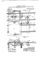
- z-- Figure 1 is a plan view of the arrangement of tracks at the lower end of the mine shaft, and showingour im roved a paratus in. osition adjacent the ower on of the she and also showing the self-dumping cage atone side of the shaft;
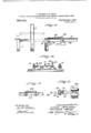
- Fig. 2 is a vertical section taken .ap roximately on the line 22 of Fig. .1;
- i 3 is a vertical section taken approximate y on the line 33 of Fig. 1;
- l is a section taken a proximately on the line 4-4 of Fig. 1;
- 1g. 5 is an on r ed detailsection taken on the line 5+5 of ig. 1; and
- Fig. 6 is an enlarged horizontal section taken on the line 66 of ig-12 eferringby nuiiierals to'the accompanying drawings:
- 1 desiates the pit formed at the lower and. of a ine shaft, and leading i to said. it are.
- the tracks 2 which are p d arranged at the sides 0 the shaft above the pit are the traverse 7b the mine ears, an
- Each cage comprises-a platform 5, pro vided on its top with a pair of rails 6, which are adapted to coincide with the track rails 2 when the cage is at its lowermost limit of movement, and fixed on top of the platform 5 and in position to engage over the Wheels of the mine car are housings 7.
- the car used in connection with this cage comprises a body 8 in the form of a box, supported in any suitable manner on traction wheels 9, which are adapted to travel on the track rails 2, and transversely disposed beneath the central portion of the body 8 is a rail 10.
- lever 19 desi natcs a lever which is fulcrumed to a brac et 20 fixed on the under side of the platform 5, and formed in said lever 19 is an opening 21, through which the downwardly bent end portion 15 of one of the dogs projects, and connecting the inner end of this lever 19 with the upturned end 14 of the corresponding do "is a link 22.
- the outer end of the lever 19 occupies a position immediately beneath the edge of theplatform 5.
- a plate 23 Fixed in the frame surroundin the pit 1 and corres onding to the side 0 the platform on w ich the lever 19 is carried is a plate 23, and held to slide thereon is a late 24, the rear end of which is connected y a rod 25 to a lever 26 carried by a rock shaft 27 operating in bearin 28 fixed on one of the cross ties immediate y adjacent the pit 1.
- this rock shaft 27 Fixed on the end of this rock shaft 27 opposite the end carrying the lever 26 is an arm 29, to which is connected one end of a chain 30, the opposite end being connected to the vertically disposed arm of a bell crank 31, which is journaled to a bracket 32 fixed on the frame surroundin the pit l, and the horizontal arm of this bell crank extends over the pit in such a manner as to be engaged by the platform of the opposite cage when the same descends to its lower limit of movement.
- the cage After automatically dumping the contents of the car, the cage descends to the lower end of the shaft, and as said cage reaches its lower limit of movement or to a oint where the rails 6 are in alinement wit the track rails 2, the outer end of the lever 19 strikes against the plate 24, which action slightly tilts said lever 19 upon its pivot point, thus swinging the up-turned end of the dog 13 connected to said lever downward into such a position as to free the cross bar or rail 10, and the car is now-free to be pushed oil from the platform 5 onto the track rails 2.
- both ca es and both sides of the shaft may be simi arly equipped, and thus the automatic release is provided for the cars carried by both cages.
- Ounimproved apparatus is simple, inexpensiv can be readily ap lied to all forms of sel dumping cages, an renders the operatio of releasin or undogging thecars at the llower end 0 the shaft entirely automatic.
- a car In an apparatus of the class described, a car, a lug carried by said car and extending transversely of the car body, a mine cage,
- a pair of spring held dogs pivotally mount" ed on the platform of the cage and adapted to engage the lug carried by the car, :i pivoted lever carried by the mine cage.
- lever carried by the mine cage.
- one end of which lever is secured to one of said dogs a moving plate located in the path of travel of the mine cage and in the vertical plane of one end of said lever, whereby on the descent of the cage said lever engages with said plate and releases the dog from the lug carried by the car.
- a car a lug carried by said car and extending transvcrsel of the car body, a mine cage, a pair 0 spriiie held dogs pivotally mounted on the platform of 16.03 'c and adapted to en age the lug carried y the car, a pivote lever carried by the mine cage, one end of which lever is secured to one of said dogs, a moving plate located in the path of travel of the mine cage and in the vertical plane of one end of said lever, a rod pivoted to said plate, and a lever pivoted to the o posite end of said rod in the path of trave of the car over the track.
- a car In an apparatus of the class described, a car, a lug carried by said car and extending transversel of the car body, a mine cage, a pair 0 sprin held dogs pivotally mounted on the plat orm of the ca c and adapted to engage the lug carried by tie car, a pivoted levercarried by the mine cage, one end of whidh lever is secured to one of said dogs, a moving plate located in the path of travel of the mine ea c and in the vertical plane of one end of sai lever, a rod pivoted to said plate, a rock shaft, and an arm secured to said rock shaft and pivoted to the opposite end of said rod.
- a car In an apparatus of the class described, a car, a lug carried by said our and extending transversely of the car bddy, a mine cage, a pair of sprin held dogs pivota'lly mounted on the plat orm of the ea c and adapted to engage the lug) carried by the car, a pivoted lever carried y the mine cage, one end of which lever is secured to one of said dogs,'a' moving plate located in the path of travel of the-mine cage and in the vertical plane of one end of said lever, a rod pivoted to said plate, a.
- rock shaft an arm secured to said rock shaft and-pivoted to the opposite end of said rod, a similar arm pivoted to the oppositeend of said rock shaft, a bell crank lever mounted in the path of travel of an adjacent mine cage, and a chain for connecting said bell crank lever and the arm carried by the opposite end of said rock shaft together.
Landscapes
- Platform Screen Doors And Railroad Systems (AREA)
Description
P. BRASGHE & W. DOELZ. V m'rom'mc DEVICE FOR BELEABING EMPTY ems mom SELF nnmm'a mum G GAGES.
APPLIUATIOH FILED 0OT.26. 1908,
Patented Aug, 3. 1909.
2 SHEETS-SHEET 1.
F. BRASGHE & W. DOBLZ. AUTOMATIC DEVICE FOR BELEASING EMPTY (mas PROM SELF DUMPING MINING GAGES.
APPLIOATIOH FILED 001226. 1908.
929,75 1 Patented Aug. 3. 1909.
2 SHEETS-SHEET 2.
6r 5 .[22 U628 40219. 1 VI @231 44 la 667 fir asfi/ze.
ZdaZZz'awz UNITED STATES PATENT OFFICE.
FRED BRASCHE AND WILLIAM DOELZ, OF BENLD, ILLINOIS.
AUTOMATIC DEVICE FOR RELEASING EMPTY CARS FROM SELF-DUMPING MINING- CAGES.
Specification of Letters Patent.
Application filed October 26, 1908.
Patented Aug. 3, 1909.
Serial No. 459,664.
To all whom it may concern:
Be it known that we, Faun BRASCHE and \Vmnmu Dorm, both citizens of the United States. and residents of Bcnld, Illinois, have invented certain new and useful Improvements in Automatic Devices for Releasing Empty Cars from Self-Dumping Miningages, of which the following is a specificatmn' containing a full, clear, and exact description, reference being had to the accompanying drawings, forming a part hereof.
()nr invention relates to an automatic device for releasing empty cars from selfdnmping mining cages, the object of our invention being to provide simple, inexpensive andautomatically operating means for releasing catches or dogs which hold mining cars on self-dumping mine cages, when said cages reach the bottom of the shaft, thus permitting the empty cars to be readily moved onto the car track in the tunnel or entry of the mine 'without necessitatingany action on the part of the operator.
1 To the above purposes, our invention consists in certain novel features of construction and arrangement of parts which will be hereinafter more full set forth pointed out in the claims, and i1 ustrated in the accompanying drawings, in which z-- Figure 1 is a plan view of the arrangement of tracks at the lower end of the mine shaft, and showingour im roved a paratus in. osition adjacent the ower on of the she and also showing the self-dumping cage atone side of the shaft; Fig. 2 is a vertical section taken .ap roximately on the line 22 of Fig. .1; i 3 is a vertical section taken approximate y on the line 33 of Fig. 1; Fig. l is a section taken a proximately on the line 4-4 of Fig. 1; 1g. 5 is an on r ed detailsection taken on the line 5+5 of ig. 1; and Fig. 6 ;is an enlarged horizontal section taken on the line 66 of ig-12 eferringby nuiiierals to'the accompanying drawings: 1 desi ates the pit formed at the lower and. of a ine shaft, and leading i to said. it are. the tracks 2 which are p d arranged at the sides 0 the shaft above the pit are the traverse 7b the mine ears, an
vertically disposed guides 3, there being a centrally disposed guide 1 located between the side guides in order that two of the selfdmn 'iing cages may operate in the shaft.
Each cage comprises-a platform 5, pro vided on its top with a pair of rails 6, which are adapted to coincide with the track rails 2 when the cage is at its lowermost limit of movement, and fixed on top of the platform 5 and in position to engage over the Wheels of the mine car are housings 7. The car used in connection with this cage comprises a body 8 in the form of a box, supported in any suitable manner on traction wheels 9, which are adapted to travel on the track rails 2, and transversely disposed beneath the central portion of the body 8 is a rail 10. Fixed on the center of the latform 5 is a pair of plates 11, and journa ed on pins 12' passing therethrough is a pair of horizontally disposed dogs or catches 13, the adjacent ends of which are bent slightly upward, as designated by 14, in order to engage on oppo its sides of the bar 10, and the outer ends of these dogs or catches are bentvertically downward, as designated by 1 5, and ro'ect throu h openings 16 formed in the at orm 5, and connecting the lower ends 0. these downwardly bent end portions 15 and centrally disposed brace 17 on the under side of the platform 5 are retractile coil springs 18.
19 desi natcs a lever which is fulcrumed to a brac et 20 fixed on the under side of the platform 5, and formed in said lever 19 is an opening 21, through which the downwardly bent end portion 15 of one of the dogs projects, and connecting the inner end of this lever 19 with the upturned end 14 of the corresponding do "is a link 22. The outer end of the lever 19 occupies a position immediately beneath the edge of theplatform 5.
Fixed in the frame surroundin the pit 1 and corres onding to the side 0 the platform on w ich the lever 19 is carried is a plate 23, and held to slide thereon is a late 24, the rear end of which is connected y a rod 25 to a lever 26 carried by a rock shaft 27 operating in bearin 28 fixed on one of the cross ties immediate y adjacent the pit 1. Fixed on the end of this rock shaft 27 opposite the end carrying the lever 26 is an arm 29, to which is connected one end of a chain 30, the opposite end being connected to the vertically disposed arm of a bell crank 31, which is journaled to a bracket 32 fixed on the frame surroundin the pit l, and the horizontal arm of this bell crank extends over the pit in such a manner as to be engaged by the platform of the opposite cage when the same descends to its lower limit of movement.
When a mine car is positioned on the patform of the cage, the wheels 9 of the car engage beneath the housings 7 and the cross bar or rail 10 occupies a position between the up-turned ends 14 of the dogs 13, and thus the car is held on the platform while the cage is raised to the top of the shaft. After automatically dumping the contents of the car, the cage descends to the lower end of the shaft, and as said cage reaches its lower limit of movement or to a oint where the rails 6 are in alinement wit the track rails 2, the outer end of the lever 19 strikes against the plate 24, which action slightly tilts said lever 19 upon its pivot point, thus swinging the up-turned end of the dog 13 connected to said lever downward into such a position as to free the cross bar or rail 10, and the car is now-free to be pushed oil from the platform 5 onto the track rails 2. As the car is pushed away from the pit a part of the framework of the car strikes against the upper end of the lever 26, thus actuating the same, which movement rocks the shaft 27 and withdraws the plate 24 from beneath the end of the lever 19, and as a result said lever will resume its normal horizontal position and the upturned end of the dog connected to said lever will be elevated into osition to be engaged by the cross bar or rail 10 of the succeeding car placed on the platform 5. The plate 24 is returned to its normal position by the action of the opposite cage en agin against the horizontal arm of the be] cran 31 and depressing the same, which movement, by reason of the connecting chain 30, rocks the shaft 27 in such a manner as to move the late 24: forward into position to be struck By the end of the lever 19.
While we have shown the automatic releasing mechanism as applied to only one cage, and half the shaft, it will be readily understood that both ca es and both sides of the shaft may be simi arly equipped, and thus the automatic release is provided for the cars carried by both cages.
Ounimproved apparatus is simple, inexpensiv can be readily ap lied to all forms of sel dumping cages, an renders the operatio of releasin or undogging thecars at the llower end 0 the shaft entirely automatic.
We claim:
1. In an apparatus of the class described, a car, a lug carried by said car and extending transversely of the car body, a mine cage,
a pair of spring held dogs pivotally mount" ed on the platform of the cage and adapted to engage the lug carried by the car, :i pivoted lever carried by the mine cage. one end of which lever is secured to one of said dogs, a moving plate located in the path of travel of the mine cage and in the vertical plane of one end of said lever, whereby on the descent of the cage said lever engages with said plate and releases the dog from the lug carried by the car.
2. In an apparatus of the class described,
a car, a lug carried by said car and extending transvcrsel of the car body, a mine cage, a pair 0 spriiie held dogs pivotally mounted on the platform of 16.03 'c and adapted to en age the lug carried y the car, a pivote lever carried by the mine cage, one end of which lever is secured to one of said dogs, a moving plate located in the path of travel of the mine cage and in the vertical plane of one end of said lever, a rod pivoted to said plate, and a lever pivoted to the o posite end of said rod in the path of trave of the car over the track.
3. In an apparatus of the class described, a car, a lug carried by said car and extending transversel of the car body, a mine cage, a pair 0 sprin held dogs pivotally mounted on the plat orm of the ca c and adapted to engage the lug carried by tie car, a pivoted levercarried by the mine cage, one end of whidh lever is secured to one of said dogs, a moving plate located in the path of travel of the mine ea c and in the vertical plane of one end of sai lever, a rod pivoted to said plate, a rock shaft, and an arm secured to said rock shaft and pivoted to the opposite end of said rod.
,4. In an apparatus of the class described, a car, a lug carried by said our and extending transversely of the car bddy, a mine cage, a pair of sprin held dogs pivota'lly mounted on the plat orm of the ea c and adapted to engage the lug) carried by the car, a pivoted lever carried y the mine cage, one end of which lever is secured to one of said dogs,'a' moving plate located in the path of travel of the-mine cage and in the vertical plane of one end of said lever, a rod pivoted to said plate, a. rock shaft, an arm secured to said rock shaft and-pivoted to the opposite end of said rod, a similar arm pivoted to the oppositeend of said rock shaft, a bell crank lever mounted in the path of travel of an adjacent mine cage, and a chain for connecting said bell crank lever and the arm carried by the opposite end of said rock shaft together.
5. In an apparatus of the class described, a car body, a lug disposed beneath the body, a mine cage, a air of spriiig'held dogs pivotally mount'e on said mine cage, a lever pivotall carried by said mine cage, one end of whic i is secured to the end of one of said dogs and the opposite end projects free be- ,In testimony whereof, we have signed our heath the platform of thecage, and a horinames to this specification, in' presence of 10 zon'tall movable means arranged in the two subscribing witnesses.
path 0 travel of the mine cage and adapted FRED BRASCHE. to be engaged with the free end of said lever WILLIAM DOELZ. for automatically releasing said dog from W'itnesses:
the lug carried by the car, upon the descent T. ZIGMAM,
of the cage; CHARLES PIEPER.
Priority Applications (1)
| Application Number | Priority Date | Filing Date | Title |
|---|---|---|---|
| US45955408A US929751A (en) | 1908-10-26 | 1908-10-26 | Automatic device for releasing empty cars from self-dumping mining-cages. |
Applications Claiming Priority (1)
| Application Number | Priority Date | Filing Date | Title |
|---|---|---|---|
| US45955408A US929751A (en) | 1908-10-26 | 1908-10-26 | Automatic device for releasing empty cars from self-dumping mining-cages. |
Publications (1)
| Publication Number | Publication Date |
|---|---|
| US929751A true US929751A (en) | 1909-08-03 |
Family
ID=2998175
Family Applications (1)
| Application Number | Title | Priority Date | Filing Date |
|---|---|---|---|
| US45955408A Expired - Lifetime US929751A (en) | 1908-10-26 | 1908-10-26 | Automatic device for releasing empty cars from self-dumping mining-cages. |
Country Status (1)
| Country | Link |
|---|---|
| US (1) | US929751A (en) |
-
1908
- 1908-10-26 US US45955408A patent/US929751A/en not_active Expired - Lifetime
Similar Documents
| Publication | Publication Date | Title |
|---|---|---|
| US1020746A (en) | Elevator. | |
| US1565949A (en) | Tipple | |
| US1229222A (en) | Crossover-dump. | |
| US470730A (en) | Hoisting device | |
| US1002984A (en) | Coal-loading apparatus. | |
| US547309A (en) | Dumping-car | |
| US1426027A (en) | Assigwos to wood equipment | |
| US1584746A (en) | Automatic lock and release for mine cars | |
| US558092A (en) | Automatic railway-gate | |
| US223922A (en) | Dumping-car | |
| US896467A (en) | Mining apparatus. | |
| US988462A (en) | Car-dumping mechanism. | |
| US734006A (en) | Railway mail-pouch-transfer system. | |
| US1509374A (en) | Feeder for kickback dumps | |
| US896787A (en) | Mail-bag delivering and receiving apparatus. | |
| US856407A (en) | Mail-bag catching and delivering mechanism. | |
| US424619A (en) | robertson | |
| US1489772A (en) | Caging apparatus | |
| US794587A (en) | Car-handling apparatus. | |
| US1079718A (en) | Loading device. | |
| US943566A (en) | Railway-crossing gate. | |
| US929659A (en) | Mail collecting and delivering device. | |
| US472159A (en) | Attachment for mining-cages | |
| US524211A (en) | Said fleming | |
| US1044460A (en) | Car-cager. |