US9297308B2 - Temperature measurement in a gas turbine - Google Patents
Temperature measurement in a gas turbine Download PDFInfo
- Publication number
- US9297308B2 US9297308B2 US13/774,676 US201313774676A US9297308B2 US 9297308 B2 US9297308 B2 US 9297308B2 US 201313774676 A US201313774676 A US 201313774676A US 9297308 B2 US9297308 B2 US 9297308B2
- Authority
- US
- United States
- Prior art keywords
- gas
- upstream
- downstream
- detection end
- seal housing
- Prior art date
- Legal status (The legal status is an assumption and is not a legal conclusion. Google has not performed a legal analysis and makes no representation as to the accuracy of the status listed.)
- Active, expires
Links
Images


Classifications
-
- F—MECHANICAL ENGINEERING; LIGHTING; HEATING; WEAPONS; BLASTING
- F02—COMBUSTION ENGINES; HOT-GAS OR COMBUSTION-PRODUCT ENGINE PLANTS
- F02C—GAS-TURBINE PLANTS; AIR INTAKES FOR JET-PROPULSION PLANTS; CONTROLLING FUEL SUPPLY IN AIR-BREATHING JET-PROPULSION PLANTS
- F02C7/00—Features, components parts, details or accessories, not provided for in, or of interest apart form groups F02C1/00 - F02C6/00; Air intakes for jet-propulsion plants
-
- F—MECHANICAL ENGINEERING; LIGHTING; HEATING; WEAPONS; BLASTING
- F01—MACHINES OR ENGINES IN GENERAL; ENGINE PLANTS IN GENERAL; STEAM ENGINES
- F01D—NON-POSITIVE DISPLACEMENT MACHINES OR ENGINES, e.g. STEAM TURBINES
- F01D11/00—Preventing or minimising internal leakage of working-fluid, e.g. between stages
- F01D11/02—Preventing or minimising internal leakage of working-fluid, e.g. between stages by non-contact sealings, e.g. of labyrinth type
- F01D11/04—Preventing or minimising internal leakage of working-fluid, e.g. between stages by non-contact sealings, e.g. of labyrinth type using sealing fluid, e.g. steam
- F01D11/06—Control thereof
-
- F—MECHANICAL ENGINEERING; LIGHTING; HEATING; WEAPONS; BLASTING
- F02—COMBUSTION ENGINES; HOT-GAS OR COMBUSTION-PRODUCT ENGINE PLANTS
- F02C—GAS-TURBINE PLANTS; AIR INTAKES FOR JET-PROPULSION PLANTS; CONTROLLING FUEL SUPPLY IN AIR-BREATHING JET-PROPULSION PLANTS
- F02C7/00—Features, components parts, details or accessories, not provided for in, or of interest apart form groups F02C1/00 - F02C6/00; Air intakes for jet-propulsion plants
- F02C7/28—Arrangement of seals
-
- F—MECHANICAL ENGINEERING; LIGHTING; HEATING; WEAPONS; BLASTING
- F05—INDEXING SCHEMES RELATING TO ENGINES OR PUMPS IN VARIOUS SUBCLASSES OF CLASSES F01-F04
- F05D—INDEXING SCHEME FOR ASPECTS RELATING TO NON-POSITIVE-DISPLACEMENT MACHINES OR ENGINES, GAS-TURBINES OR JET-PROPULSION PLANTS
- F05D2240/00—Components
- F05D2240/55—Seals
- F05D2240/57—Leaf seals
-
- F—MECHANICAL ENGINEERING; LIGHTING; HEATING; WEAPONS; BLASTING
- F05—INDEXING SCHEMES RELATING TO ENGINES OR PUMPS IN VARIOUS SUBCLASSES OF CLASSES F01-F04
- F05D—INDEXING SCHEME FOR ASPECTS RELATING TO NON-POSITIVE-DISPLACEMENT MACHINES OR ENGINES, GAS-TURBINES OR JET-PROPULSION PLANTS
- F05D2270/00—Control
- F05D2270/30—Control parameters, e.g. input parameters
- F05D2270/303—Temperature
Definitions
- the present invention relates to a gas turbine and in particular to a structure for measuring the temperature between a rotor disk of a rotor and an inner portion of a turbine vane in a radial direction of the rotor.
- a rotor of the gas turbine described in Patent Document 1 has a rotor disk of each of a plurality of stages, and a plurality of blades fixed to the rotor disk. Further, a plurality of vanes of the gas turbine is disposed on the upstream sides of the blades of each of the plurality of stages. An upstream-side rim portion which protrudes to the upstream side and first and second downstream-side rim portions which protrude to the downstream side are formed at the rotor disk of each of the plurality of stages. The second downstream-side rim portion of the rotor disk is located further radially inward than the first downstream-side rim portion and faces the upstream-side rim portion of a downstream-side rotor disk adjacent to the downstream side of the rotor disk.
- a seal housing which faces the second downstream-side rim portion of the rotor disk on the upstream side with respect to the vane and the upstream-side rim portion of the rotor disk on the downstream side with respect to the vane is fixed to the inside of the vane in the radial direction.
- a first upstream-side seal member which performs sealing between the seal housing and the first downstream-side rim portion of the upstream-side rotor disk, a second upstream-side seal member which performs sealing between the seal housing and the second downstream-side rim portion of the upstream-side rotor disk., and a downstream-side seal member which performs sealing between the seal housing and the upstream-side rim portion of the downstream-side rotor disk are provided at the seal housing.
- thermometer for measuring the temperature of gas in a disk cavity between the seal housing and the rotor disk on the upstream side and the rotor disk on the downstream side with respect to the seal housing is provided.
- a detection space in which a temperature detection end of the thermometer is inserted, a gas introduction path extending from the detection point space to the upstream side along an axis of rotation, and a gas discharge path extending from the detection end space to the downstream side along the axis of rotation are formed.
- An introduction port of the gas introduction path is located further to the upstream side than the first upstream-side seal member provided at the seal housing and on the outside in the radial direction.
- a discharge port of the gas discharge path is located further to the downstream side than the downstream-side seal member provided at the seal housing and on the outside in the radial direction.
- thermometer detects the temperature of gas which flows in from the introduction port of the gas introduction path, that is, gas in an area of the disk cavity further on the upstream side and further on the outside in the radial direction than the first upstream-side seal member.
- thermometer in which a body portion of the thermometer is bent such that a detection end provided at the tip of the body portion can detect the temperature of gas in a target area in the disk cavity.
- Patent Document 1 Japanese Unexamined Patent Application. First Publication No. 2010-196664
- Patent Document 2 Japanese Unexamined Patent Application, First Publication No. 2002-322918
- the present invention has an object to provide a gas turbine in which a problem of temperature detection failure is small and temperature management of a rotor disk can be easily performed.
- a rotor that rotates around an axis of rotation; a casing that covers the rotor so as to be rotatable; and a vane fixed to the casing,
- the rotor has a rotor disk centered on the axis of rotation and a plurality of blades fixed to the rotor disk and arranged in a circumferential direction with respect to the axis of rotation, in each of a plurality of stages arranged in an axial direction in which the axis of rotation extends, and a plurality of the vanes are disposed side by side in the circumferential direction on the upstream side of the blades in each of the plurality of stages,
- annular seal housing is fixed to the inside of the vane in a radial direction of the rotor
- an upstream-side seal member facing the downstream-side rim portion on the upstream side with respect to the seal housing is provided in the seal housing, and a detection end space in which a temperature detection end of a thermometer is accommodated, a gas introduction path which leads gas in a disk cavity between the seal housing and the upstream-side rim portion on the downstream side with respect to the seal housing and the downstream-side rim portion to the detection end space, and a gas discharge path that discharges gas, which has reached the detection end space, further to the downstream side than an introduction port of the gas introduction path are also formed in the seal housing,
- the detection end space is formed at a radially outer position with respect to the upstream-side seal member
- the introduction port of the gas introduction path is formed at a position further on the downstream side than the upstream-side seal member, and the gas introduction path has a radially extending portion which extends toward the outside in the radial direction from the introduction port, and an axially extending portion which extends from an outer end portion of the radially extending portion to the upstream side along the axis of rotation and reaches the detection end space.
- the disk cavity between the seal housing and the upstream-side or downstream-side rim portions is little affected by combustion gas which flows back from a combustion gas flow path of the gas turbine. For this reason, even if the ratio between the combustion gas and cooling gas changes and thus the flows of the combustion gas and the cooling gas change, by detecting the temperature of gas in the disk cavity, it is possible to reliably detect the temperature of gas according to the ratio.
- a downstream-side seal member facing the upstream-side rim portion on the downstream side with respect to the seal housing may be provided in the seal housing, and the introduction port of the gas introduction path may be formed at a position further on the upstream side than the downstream-side seal member.
- An area between the upstream-side seal member and the downstream-side seal member is an area in which the temperature non-uniformity in the circumferential direction is relatively small. For this reason, it is possible to reliably detect the temperature of gas in the disk cavity.
- the upstream-side seal member may be a brush seal or a leaf-shaped seal.
- sealing performance between the rotor and the vane can be increased.
- the gas discharge path may extend from the detection end space to the downstream side along the axis of rotation.
- each gas flow path which is formed in the seal housing is linearly made, hole drilling on the seal housing for forming each gas flow path can be easily performed.
- a gas path forming hole which extends from the detection end space to the downstream side along the axis of rotation and in which a portion of an internal space forms the axially extending portion of the gas introduction path and the gas discharge path may he formed in the seal housing, and a partition member partitioning the internal space into the axially extending portion of the gas introduction path and the gas discharge path may be inserted and mounted in the gas path forming hole.
- hole drilling on the seal housing can be more easily performed.
- a problem of temperature detection failure is reduced and the temperature management of the rotor disk can be easily performed.
- FIG. 1 is a schematic diagram showing the configuration of a gas turbine in an embodiment related to the invention.
- FIG 2 is a cross-sectional view of a main section of the gas turbine in the embodiment related to the invention.
- FIG. 3 is a detailed cross-sectional view of the circumferences of a rotor disk and a seal housing in FIG. 2 .
- FIG. 4 is a detailed cross-sectional view of the circumference of the seal housing in
- FIG 3 is a diagrammatic representation of FIG. 1 .
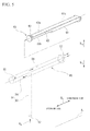
- FIG. 5 is a perspective view of a gas path forming hole and a partition member in the embodiment related to the invention.
- FIGS. 1 to 5 An embodiment of a gas turbine according to the invention will be described in detail referring to FIGS. 1 to 5 .
- a gas turbine of this embodiment includes a compressor 1 which compresses external air to generate compressed air, a plurality of combustors 2 which mixes fuel from a fuel supply source with the compressed air and bums the mixture, thereby generating combustion gas, and a turbine 3 which is driven by the combustion gas, as shown in FIG 1 .
- the turbine 3 includes a easing 5 , and a rotor 10 which rotates in the casing 5 , as shown in FIG 2 .
- an electric generator 4 FIG. 1
- a direction in which an axis of rotation Ar that is the center of rotation of the rotor 10 extends is referred to as an axial direction Da.
- a side coming close to the axis of rotation Ar is referred to as the radially inner side and a side getting away from the axis of rotation Ar is referred to as the radially outer side.
- the rotor 10 has a rotor disk 11 centered on the axis of rotation Ar, and a plurality of blades 21 fixed to the rotor disk 11 and arranged in a circumferential direction Dc with respect to the axis of rotation Ar, for each of a plurality of stages arranged in the axial. direction Da.
- a plurality of vanes 31 is fixed to the inner periphery of the casing 5 at the upstream sides of the blades 21 in each of the plurality of stages.
- the plurality of vanes 31 of each stage is disposed side by side in the circumferential direction Dc with respect to the axis of rotation Ar.
- a seal housing 40 is fixed to the radially inner side.
- a thermometer 80 for measuring the temperature of gas in a disk cavity C between the seal housing 40 and the rotor disk 11 on the upstream side and the rotor disk 11 on the downstream side with respect to the seal housing 40 is provided.
- the thermometer 80 has a detection end 81 , a straight body portion 82 linearly extending from the detection end 81 , and a terminal box 83 provided at an end portion of the straight body portion 82 .
- the thermometer 80 in this embodiment is a thermocouple thermometer and end portions of two metal wires formed of different materials forming a thermocouple are accommodated in the terminal box 83 .
- a thermocouple thermometer is used as the thermometer 80 .
- other types of thermometers such as a resistance thermometer, for example, may be used.
- Thermometer passing-through holes 5 h and 31 h in which the detection end 81 and the straight body portion 82 of the thermometer 80 are inserted are formed in the casing 5 and the vane 31 . Further, a detection end space 55 which communicates with the thermometer passing-through hole 31 h of the vane 31 and in which the detection end 81 of the thermometer 80 is accommodated is formed in the seal housing 40 .
- an upstream-side rim portion 12 which protrudes to the upstream side and a first downstream-side rim portion 14 and a second downstream-side rim portion 15 which protrude to the downstream side are formed at the rotor disk 11 of each of the plurality of stages.
- the second downstream-side rim portion 15 of the rotor disk 11 is located further to the radially inner side than the first downstream-side rim portion 14 .
- the second downstream-side rim portion 15 faces the upstream-side rim portion 12 of a downstream-side rotor disk lid adjacent to the downstream side of the rotor disk 11 and an air baffle 19 is provided between the two.
- the blade 21 which is fixed to the rotor disk 1 . 1 has a blade main body 22 extending in the radial direction Dr, a platform 23 provided on the radially inner side of the blade main body 22 . a shank 24 provided on the radially inner side of the platform 23 , and a blade root (not shown) provided on the radially inner side of the shank 24 , The blade root of the blade 21 is inserted into the rotor disk 11 whereby the blade 21 is fixed to the rotor disk 11 .
- the vane 31 fixed to the casing 5 has a vane main body 32 extending to the radially inner side from the inner peripheral surface of the easing 5 , an inner shroud 33 provided on the radially inner side of the vane main body 32 , and a leg portion 34 extending to the radially inner side from the inner shroud 33 .
- a seal tube 39 which supplies some of cooling gas A that is the compressed air extracted from the hallway of the compressor 1 ( FIG 1 ) to the inner shroud 33 for cooling of the vane 31 , is disposed in the vane main body 32 so as to pass through the vane main body 32 in the radial direction Dr. and is opened to an inner shroud cavity 38 at a terminus thereof.
- An outer facing portion 41 which faces the first downstream-side rim portion 14 of an upstream-side rotor disk 11 u with respect to the seal housing 40 in the radial direction Dr, is formed on the radially inner side of the seal housing 40 , as shown in FIG. 3 .
- an inner facing portion 42 which faces each of the second downstream-side rim portion 15 of the upstream-side rotor disk 11 u and the upstream-side rim portion 12 of the downstream-side rotor disk 11 d in the radial direction Dr is formed on the radially inner side of the seal housing 40 .
- the outer facing portion 41 is formed at a position on the upstream side and at a radially outer position with respect to the inner facing portion 42 .
- a fin seal 71 performing sealing between the outer facing portion 41 of the seal housing 40 and the first downstream-side rim portion 14 of the upstream-side rotor disk 11 u which faces the outer facing portion 41 in the radial direction Dr is provided at the outer facing portion 41 .
- a leaf-shaped seal fan upstream-side seal member 72 performing sealing between the inner facing portion 42 and the second downstream-side rim portion 15 of the upstream-side rotor disk 11 u which faces the inner facing portion 42 in the radial direction Dr is provided.
- a labyrinth seal (a downstream-side seal member) 73 performing sealing between the inner facing portion 42 and the upstream-side rim portion 12 of the downstream-side rotor disk 11 d which, feces the inner facing portion 42 in the radial direction Dr is provided.
- the above-described detection end space 55 formed in the seal housing 40 is formed at a radially outer position with respect to the leaf-shaped seal 72 .
- an area facing the shank 24 of the blade 21 on the upstream side is set to be a first cavity C 1 .
- the first cavity C 1 is an area further on the upstream side and further radially outer side than the fin seal 71 provided at the seal housing 40 .
- an area further on the downstream side than the fin seal 71 and further on the upstream side than the leaf-shaped seal 72 is set to be a second cavity C 2 .
- an area further on the downstream side than the leaf-shaped seal 72 and. further on. the upstream side than the labyrinth seal 73 is set to be a third cavity C 3 .
- the leaf-shaped seal 72 is provided with a large number of lamina seal pieces and a retention portion which retains end portions of the large number of lamina seal pieces.
- the large number of lamina seal pieces are arranged around a rotating body (in this case, the second downstream-side rim portion 15 of the rotor disk 11 ) with a thickness direction of each lamina seal piece directed in the circumferential direction Dc of the rotating body and with a minute gap held with respect to one another in the circumferential direction Dc.
- a radially inner end portion of each lamina, seal piece is a free end and a radially outer end portion is retained by the retention portion.
- Each lamina seal piece is disposed to be inclined such that the radially inner free end is located further to the rotation direction side of the rotating body than the radially outer fixed end portion.
- each lamina seal piece In the leaf-shaped seal 72 , the free end of each lamina seal piece is in contact with the rotating body when the rotating body remains stationary. However, when the rotating body rotates, the free end of each lamina seal piece rises from the outer peripheral surface of the rotating body due to a dynamic pressure effect which is generated by the rotation of the rotating body, thereby entering a non-contact state with the rotating body. For this reason, the leaf-shaped seal 72 has extremely high sealing performance and also has high durability.
- the fin seal 71 and the leaf-shaped seal 72 described above are provided in order to prevent the combustion gas G, which flows back from the combustion gas flow path GP to the disk cavity C on the upstream side, from entering the rotor side disk cavity C which is on the radially inner side.
- the leaf-shaped seal 72 having high sealability is disposed on the farthest upstream side of the inner facing portion 42 , whereby a variation in the space temperature of the third cavity C 3 surrounded by the leaf-shaped seal 72 and the labyrinth seal 73 are suppressed, the leaf-shaped seal 72 is important.
- connection portion 43 which is connected to the leg portion 34 of the inner shroud 33 is provided at the radially outer side of the seal housing 40 .
- a gas introduction path 51 which leads gas Gm in the third cavity C 3 which is formed between the leaf-shaped seal 72 and the labyrinth seal 73 to the detection end space 55 and a gas discharge path 56 which discharges the gas that has reached the detection end space 55 are formed in the seal housing 40 , as shown in FIG. 4 .
- a purge hole 49 of which one side is opened to the inner shroud cavity 38 and the other side is opened to the second cavity C 2 is formed in the outer facing portion 41 of the seal housing 40 .
- An introduction port 52 of the gas introduction path 51 is formed at the inner facing portion 42 of the seal housing 40 and between the leaf-shaped seal 72 and the labyrinth seal 73 .
- the gas introduction path 51 has a radially extending portion 53 extending toward the radially outer side from the introduction port 52 , and an axially extending portion 54 extending from an outer end portion of the radially extending portion 53 to the upstream side along the axis of rotation Ar and reaching the radially inner position of the detection end space 55 .
- the gas discharge path 56 extends from the radially outer position of the detection end space 55 to the downstream side along the axis of rotation Ar.
- a discharge port 57 of the gas discharge path 56 is located further to the radially outer side than the labyrinth seal 73 .
- the detection end space 55 extends toward the radially outer side from an upstream-side end of the axially extending portion 54 of the gas introduction path 51 and is connected to the gas discharge path 56 at a radial outer end thereof.
- thermometer 80 which is inserted to the seal housing 40 toward the radially inner side from the outside of the casing 5 (shown in FIG. 2 ) is inserted by passing through the vane main body 32 .
- the thermometer 80 cannot, help but be disposed further to the upstream side than an intermediate portion of the seal housing 40 in the axial direction Da in the seal housing 40 and it is difficult to dispose the thermometer 80 on the downstream side.
- the leaf-shaped seal 72 be disposed on the farthest upstream side of the inner facing portion 42 of the seal housing 40 and the introduction port 52 be disposed at a position facing the third cavity C 3 in which a variation in space temperature is suppressed, that is, on the downstream side of the leaf-shaped seal 72 .
- the radially extending portion 53 of the gas introduction path 51 it is difficult to dispose the radially extending portion 53 of the gas introduction path 51 at the same position as the thermometer 80 or further to the upstream side than the thermometer 80 when viewed in a horizontal direction on the planes of paper of FIGS. 3 and 4 , and the axially extending portion 54 extending from the outer end portion of the radially extending portion 53 to the upstream, side along the axis of rotation Ar cannot help but be provided.
- a columnar gas path forming hole 65 extending from a downstream end portion of the outer facing portion 41 to the downstream side along the axis of rotation Ar is formed in the seal housing 40 , as shown in FIGS. 4 and 5 .
- a partition member 60 is inserted and mounted in an internal space of the gas path forming hole 65 , whereby the gas discharge path 56 , the detection end space 55 , and the axially extending portion 54 of the gas introduction path 51 are formed respectively.
- the partition member 60 has a semi-columnar portion 61 which fills a radially inner space while securing a radially outer space in a space on the downstream side of the internal space of the gas path, forming hole 65 extending in a direction along the axis of rotation Ar, and a partition plate portion 62 which partitions a space on the upstream side of the internal space of the gas path forming hole 65 into a radially outer space and a radially inner space, as shown in FIG. 5 .
- a planar surface 61 a facing the inner peripheral surface on the radially outer side of the gas path forming hole 65 in which the partition member 60 is inserted is flush with a radially outer surface 62 a of the partition plate portion 62 .
- a through-hole 63 passing through the partition plate portion 62 in the radial direction Dr is formed in an upstream-side end portion of the partition plate portion 62 .
- the partition member 60 described above is mounted in the gas path forming hole 65 , whereby the axially extending portion 54 of the gas introduction path 51 and the gas discharge path 56 are formed in the internal space of the gas path forming hole 65 . That is, in the internal space of the gas path forming hole 65 , an area surrounded by the inner peripheral surface on the radially inner side of the gas path forming hole 65 and a surface 62 b on the radially inner side of the partition plate portion 62 of the partition member 60 forms the axially extending portion 54 of the gas introduction path 51 .
- an area surrounded by the inner peripheral surface on the radially outer side of the gas path forming hole 65 , the surface 62 a on the radially outer side of the partition plate portion 62 of the partition member 60 , and the planar surface 61 a of the semi-columnar portion 61 forms the gas discharge path 56 . Further, the upstream-side end portion of the partition plate portion 62 reaches the detection end space 55 .
- the through-hole 63 formed in the upstream-side end portion of the partition plate portion 62 is a hole in which the detection end 81 of the thermometer 80 is inserted, and is also a hole for sending gas that has reached the detection end space 55 from the axially extending portion 54 of the gas introduction path 51 to the gas discharge path 56 side.
- the high-temperature and high-pressure combustion gas G from the combustor 2 passes through the combustion gas flow path GP described above and comes into contact with the blade 21 in the process, thereby rotating the rotor 10 having the blade 21 around the axis of rotation Ar.
- cooling gas A (a dashed-dotted line in FIGS. 3 and 4 ) supplied from the outside of the casing 5 to the seal tube 39 provided in the vane 31 passes through the inner shroud cavity 38 and is then purged little by little through the purge hole 49 to the second cavity C 2 .
- Some of the cooling gas A purged leaks from the fin seal 71 to the first cavity C 1 on the upstream side and is discharged to the combustion gas flow path GP through the disk cavity C 1 .
- the cooling gas A that has leaked from the leaf-shaped seal 72 to the third cavity C 3 on the downstream side leaks from the labyrinth seal 73 further on the downstream side, thereby being discharged to the disk cavity on the downstream side and then discharged to the combustion gas flow path GP. Therefore, during normal operation, the pressure of the disk cavity C is always maintained higher than the pressure in the combustion gas flow path GP, and thus a backflow of the combustion gas G to the disk cavity C is prevented.
- the first cavity C 1 there is a possibility that the temperature in the circumferential direction may become non-uniform due to a local backflow, rather than an essential backflow of the combustion gas G, due to the influence of blades arranged in the combustion gas flow path GP.
- the first cavity C 1 is not suitable as a temperature detection place.
- the cooling gas A is always purged little by little through the purge hole 49 . Therefore, in a case where the second cavity C 2 is set as a temperature detection place, even if some of the combustion gas G flows back into the disk cavity C, there is the possibility of measuring the temperature of the cooled air A purged, rather than the combustion gas G flowed back, and in this case, there is a possibility that the phenomenon of the backflow of the combustion gas G cannot be detected. For this reason, it is also not preferable to manage the temperature of the rotor disk 11 by using the temperature of gas in the second cavity C 2 .
- the cooling gas A purged through the purge hole 49 flows in the third cavity C 3 through the leaf-shaped seal 72 .
- the temperature distribution in the circumferential direction is in a relatively averaged state and risk of false detection due to disposition of a detection place is small. Accordingly by detecting the temperature of gas in the third cavity C 3 , temperature management of the rotor disk 11 becomes easy.
- thermometer 80 Even if an attempt to linearly extend the thermometer 80 toward the third cavity C 3 is made in order to detect the temperature of the gas Gm in the third cavity C 3 , since the leaf-shaped seal 72 is provided radially inside the thermometer 80 , it is not possible to linearly extend the thermometer 80 . Therefore, by bending the thermometer 80 , it is possible to dispose the detection end 81 of the thermometer 80 in the third cavity C 3 .
- thermometer 80 is bent, stress is concentrated on a bent portion by vibration of the vane 31 or the seal housing 40 and in addition, a portion which guides the position of the thermometer 80 and the vicinity of the bent portion of the thermometer 80 relatively intensely come into contact with each other, thereby being subjected to wear, or the like, whereby detection may become poor.
- the detection end space 55 is disposed at a radially outer position with respect to the leaf-shaped seal 72 in the seal housing 40 . Further, the gas introduction path 51 which leads the gas Gm in the third cavity C 3 between the leaf-shaped seal 72 and the labyrinth seal 73 in the disk cavity C to the detection end space 55 , and the gas discharge path 56 which discharges the gas Gm that has reached the detection end space 55 are formed in the seal housing 40 . For this reason, in this embodiment, it is possible to detect the temperature of the gas Gm in the third cavity C 3 without bending the thermometer 80 , and thus the temperature management of the rotor disk 11 is easily performed.
- the gas Gm in the third cavity C 3 flows from the introduction port 52 of the seal housing 40 through the gas introduction path 51 into the detection end space 55 and comes into contact with the detection end 81 of the thermometer 80 here, whereby the temperature of the gas Gm is measured.
- the gas Gm which has flowed in the detection end space 55 then passes through the gas discharge path 56 and is discharged from the discharge port 57 to an area further on the downstream side than the seal housing 40 in the disk cavity C.
- the radially extending portion 53 of the gas introduction path 51 linearly extends toward the radially outer side
- the axially extending portion 54 of the gas introduction path 51 linearly extends to the upstream side along the axis of rotation Ar
- the gas discharge path 56 linearly extends to the downstream side along the axis of rotation Ar. That is, all the gas flow paths in this embodiment are linear. For this reason, in forming the gas flow paths by processing the seal housing 40 , it is possible to easily machine the seal housing 40 .
- the columnar gas path forming hole 65 is formed so as to extend from the downstream end portion of the outer facing portion 41 to the downstream side along the axis of rotation Ar. Then, the partition member 60 is inserted and mounted in the internal space of the gas path forming hole 65 , whereby the gas discharge path 56 , the detection end space 55 , and the axially extending portion 54 of the gas introduction path 51 are formed respectively. For this reason, in this embodiment, in addition, it is possible to easily perform hole drilling on the seal housing 40 .
- the leaf-shaped seal 72 is used as the upstream-side seal member.
- other seals such as a brush seal are also acceptable.
- the brush seal is a seal in which a plurality of metal wires is bundled, an end portion on one side of a bundle of the metal wires is retained by a retention portion, and an end on the other side is a free end and faces the outer peripheral surface of the rotating body.
- the labyrinth seal 73 is used as the downstream-side seal member. However, instead of this, other seals may be used.
- the invention relates to a gas turbine and in particular to a structure for measuring the temperature between a rotor disk of a rotor and a portion on the radially inner side of a vane.
- a problem of the temperature detection failure is reduced and temperature management of the rotor disk can be easily performed.
- thermometer 80 thermometer
Landscapes
- Engineering & Computer Science (AREA)
- Mechanical Engineering (AREA)
- General Engineering & Computer Science (AREA)
- Chemical & Material Sciences (AREA)
- Combustion & Propulsion (AREA)
- Turbine Rotor Nozzle Sealing (AREA)
- Measuring Temperature Or Quantity Of Heat (AREA)
Abstract
Description
Claims (5)
Applications Claiming Priority (2)
| Application Number | Priority Date | Filing Date | Title |
|---|---|---|---|
| JP2012039578A JP5818717B2 (en) | 2012-02-27 | 2012-02-27 | gas turbine |
| JP2012-039578 | 2012-02-27 |
Publications (2)
| Publication Number | Publication Date |
|---|---|
| US20130272860A1 US20130272860A1 (en) | 2013-10-17 |
| US9297308B2 true US9297308B2 (en) | 2016-03-29 |
Family
ID=49267297
Family Applications (1)
| Application Number | Title | Priority Date | Filing Date |
|---|---|---|---|
| US13/774,676 Active 2034-08-18 US9297308B2 (en) | 2012-02-27 | 2013-02-22 | Temperature measurement in a gas turbine |
Country Status (2)
| Country | Link |
|---|---|
| US (1) | US9297308B2 (en) |
| JP (1) | JP5818717B2 (en) |
Cited By (2)
| Publication number | Priority date | Publication date | Assignee | Title |
|---|---|---|---|---|
| US11504813B2 (en) | 2020-05-18 | 2022-11-22 | Rolls-Royce Plc | Methods for health monitoring of ceramic matrix composite components in gas turbine engines |
| US20240368993A1 (en) * | 2021-03-31 | 2024-11-07 | Safran Aircraft Engines | Device for sealing and reinjecting a bypass flow for a turbine nozzle |
Families Citing this family (5)
| Publication number | Priority date | Publication date | Assignee | Title |
|---|---|---|---|---|
| US9394800B2 (en) * | 2013-01-21 | 2016-07-19 | General Electric Company | Turbomachine having swirl-inhibiting seal |
| DE102015226732A1 (en) * | 2015-12-24 | 2017-06-29 | Rolls-Royce Deutschland Ltd & Co Kg | Sensor arrangement and measuring method for a turbomachine |
| CN112577755B (en) * | 2020-12-11 | 2022-04-19 | 中国科学院工程热物理研究所 | An Experimental Device for Turbine Hub Sealing Considering Upstream Unsteady Effects |
| CN112594014B (en) * | 2020-12-15 | 2022-05-20 | 中国科学院工程热物理研究所 | A air feeder that seals for transonic turbine plane cascade experiment |
| US20250277459A1 (en) * | 2024-02-29 | 2025-09-04 | Rtx Corporation | Cutting tool support for in-situ hole manufacturing |
Citations (10)
| Publication number | Priority date | Publication date | Assignee | Title |
|---|---|---|---|---|
| JPS58113824A (en) | 1981-12-22 | 1983-07-06 | ウエスチングハウス エレクトリック コ−ポレ−ション | Detector for temperature of turbin disk void |
| US4730979A (en) * | 1985-12-23 | 1988-03-15 | General Electric Company | Sensor guide tube assembly for turbine with clearance restoration adjustment |
| JPH04292530A (en) | 1990-12-27 | 1992-10-16 | United Technol Corp <Utc> | Adjustable gas turbine cooling air |
| US20010051095A1 (en) * | 1999-10-01 | 2001-12-13 | Margaret Jones Schotsch | Turbine nozzle stage having thermocouple guide tube |
| JP2002322918A (en) | 2001-03-07 | 2002-11-08 | General Electric Co <Ge> | Operating method of gas turbine engine and the equipment |
| JP2004028036A (en) | 2002-06-28 | 2004-01-29 | Hitachi Ltd | Gas turbine vane and gas turbine |
| US6832891B2 (en) * | 2001-10-29 | 2004-12-21 | Man Turbomaschinen Ag | Device for sealing turbomachines |
| JP2010196664A (en) | 2009-02-26 | 2010-09-09 | Mitsubishi Heavy Ind Ltd | Temperature sensing device, turbine stator vane, and gas turbine |
| US8371804B2 (en) * | 2005-09-06 | 2013-02-12 | Mtu Aero Engines Gmbh | Gas turbine comprising a unit for detecting a shaft rupture |
| US8400501B2 (en) * | 2008-05-12 | 2013-03-19 | Rolls-Royce Plc | Inspection arrangement |
-
2012
- 2012-02-27 JP JP2012039578A patent/JP5818717B2/en active Active
-
2013
- 2013-02-22 US US13/774,676 patent/US9297308B2/en active Active
Patent Citations (11)
| Publication number | Priority date | Publication date | Assignee | Title |
|---|---|---|---|---|
| JPS58113824A (en) | 1981-12-22 | 1983-07-06 | ウエスチングハウス エレクトリック コ−ポレ−ション | Detector for temperature of turbin disk void |
| US4730979A (en) * | 1985-12-23 | 1988-03-15 | General Electric Company | Sensor guide tube assembly for turbine with clearance restoration adjustment |
| JPH04292530A (en) | 1990-12-27 | 1992-10-16 | United Technol Corp <Utc> | Adjustable gas turbine cooling air |
| US20010051095A1 (en) * | 1999-10-01 | 2001-12-13 | Margaret Jones Schotsch | Turbine nozzle stage having thermocouple guide tube |
| JP2002322918A (en) | 2001-03-07 | 2002-11-08 | General Electric Co <Ge> | Operating method of gas turbine engine and the equipment |
| US6546735B1 (en) * | 2001-03-07 | 2003-04-15 | General Electric Company | Methods and apparatus for operating turbine engines using rotor temperature sensors |
| US6832891B2 (en) * | 2001-10-29 | 2004-12-21 | Man Turbomaschinen Ag | Device for sealing turbomachines |
| JP2004028036A (en) | 2002-06-28 | 2004-01-29 | Hitachi Ltd | Gas turbine vane and gas turbine |
| US8371804B2 (en) * | 2005-09-06 | 2013-02-12 | Mtu Aero Engines Gmbh | Gas turbine comprising a unit for detecting a shaft rupture |
| US8400501B2 (en) * | 2008-05-12 | 2013-03-19 | Rolls-Royce Plc | Inspection arrangement |
| JP2010196664A (en) | 2009-02-26 | 2010-09-09 | Mitsubishi Heavy Ind Ltd | Temperature sensing device, turbine stator vane, and gas turbine |
Non-Patent Citations (1)
| Title |
|---|
| Office Action dated Sep. 1, 2015, issued in counterpart Japanese Patent Application No. 2012-039578, with English translation (6 pages). |
Cited By (3)
| Publication number | Priority date | Publication date | Assignee | Title |
|---|---|---|---|---|
| US11504813B2 (en) | 2020-05-18 | 2022-11-22 | Rolls-Royce Plc | Methods for health monitoring of ceramic matrix composite components in gas turbine engines |
| US20240368993A1 (en) * | 2021-03-31 | 2024-11-07 | Safran Aircraft Engines | Device for sealing and reinjecting a bypass flow for a turbine nozzle |
| US12305515B2 (en) * | 2021-03-31 | 2025-05-20 | Safran Aircraft Engines | Device for sealing and reinjecting a bypass flow for a turbine nozzle |
Also Published As
| Publication number | Publication date |
|---|---|
| US20130272860A1 (en) | 2013-10-17 |
| JP5818717B2 (en) | 2015-11-18 |
| JP2013174195A (en) | 2013-09-05 |
Similar Documents
| Publication | Publication Date | Title |
|---|---|---|
| US9297308B2 (en) | Temperature measurement in a gas turbine | |
| US9880059B2 (en) | Gas turbine exhaust diffuser mounted blade path thermocouple probe | |
| US9650909B2 (en) | Multi-stage compressor fault detection and protection | |
| US8707711B2 (en) | Sealing apparatus with multistage brush seal | |
| KR101604939B1 (en) | Gas turbine | |
| US8734095B2 (en) | Gas turbine | |
| US20140064924A1 (en) | Tip clearance probe for turbine applications | |
| US20170184472A1 (en) | Sensor arrangement and measurement method for a turbomachine | |
| CN103562502B (en) | Piston seal ring | |
| JP2010065698A (en) | Shroud for turbo machine | |
| JP2013139800A (en) | Double ended brush seal assembly for compressor | |
| US20170159446A1 (en) | Methods and systems for determining wear in a turbine engine | |
| US10655481B2 (en) | Cover plate for rotor assembly of a gas turbine engine | |
| JP2016084808A (en) | System for routing rotatable wire bundles of turbomachine | |
| CN107076028A (en) | Containment member | |
| US11340184B2 (en) | Engine component performance inspection sleeve and method of inspecting engine component | |
| JP2012145101A (en) | Method, system and apparatus for detecting material defect in combustor of combustion turbine engine | |
| US9416679B2 (en) | Borescope assembly and method of installing borescope plugs | |
| CN102608198B (en) | For the method for the fault in material of detection rotor blade, system and apparatus | |
| US11788431B2 (en) | Endwall plug cooling system | |
| CA2756371C (en) | Seal arrangement | |
| Romagnoli et al. | Comparison Between the Steady Performance of Double-Entry and Twin-Entry Turbocharger Turbines | |
| US11353214B2 (en) | Gas turbine | |
| CN115997066A (en) | Tool for aligning the sealing section |
Legal Events
| Date | Code | Title | Description |
|---|---|---|---|
| AS | Assignment |
Owner name: MITSUBISHI HEAVY INDUSTRIES, LTD., JAPAN Free format text: ASSIGNMENT OF ASSIGNORS INTEREST;ASSIGNORS:TSUTSUMI, EIICHI;ARASE, KENICHI;REEL/FRAME:030672/0873 Effective date: 20130618 |
|
| AS | Assignment |
Owner name: MITSUBISHI HITACHI POWER SYSTEMS, LTD., JAPAN Free format text: ASSIGNMENT OF ASSIGNORS INTEREST;ASSIGNOR:MITSUBISHI HEAVY INDUSTRIES, LTD.;REEL/FRAME:034858/0078 Effective date: 20150129 |
|
| STCF | Information on status: patent grant |
Free format text: PATENTED CASE |
|
| MAFP | Maintenance fee payment |
Free format text: PAYMENT OF MAINTENANCE FEE, 4TH YEAR, LARGE ENTITY (ORIGINAL EVENT CODE: M1551); ENTITY STATUS OF PATENT OWNER: LARGE ENTITY Year of fee payment: 4 |
|
| AS | Assignment |
Owner name: MITSUBISHI POWER, LTD., JAPAN Free format text: CHANGE OF NAME;ASSIGNOR:MITSUBISHI HITACHI POWER SYSTEMS, LTD.;REEL/FRAME:054975/0438 Effective date: 20200901 |
|
| AS | Assignment |
Owner name: MITSUBISHI POWER, LTD., JAPAN Free format text: CORRECTIVE ASSIGNMENT TO CORRECT THE REMOVING PATENT APPLICATION NUMBER 11921683 PREVIOUSLY RECORDED AT REEL: 054975 FRAME: 0438. ASSIGNOR(S) HEREBY CONFIRMS THE ASSIGNMENT;ASSIGNOR:MITSUBISHI HITACHI POWER SYSTEMS, LTD.;REEL/FRAME:063787/0867 Effective date: 20200901 |
|
| MAFP | Maintenance fee payment |
Free format text: PAYMENT OF MAINTENANCE FEE, 8TH YEAR, LARGE ENTITY (ORIGINAL EVENT CODE: M1552); ENTITY STATUS OF PATENT OWNER: LARGE ENTITY Year of fee payment: 8 |