BACKGROUND OF THE INVENTION
1. Field of the Invention
This application is a continuation-in-part of U.S. patent application Ser. No. 13/282,391, filed Oct. 26, 2011, and titled “WINDSHIELD WIPER WITH EVEN PRESSING FORCE”. The entire disclosures of the above application are all incorporated herein by reference.
2. Description of Prior Art
Automotive windshield wiper is mounted on an outer surface of a windshield of a car. The windshield wiper is connected to a driving arm. The driving arm drives the windshield wiper to swing on the windshield.
The windshield wiper is used to wipe out rains, fogs or sludge on the windshield, so that the driver can have a good vision and an enhanced safety in driving. Thus, preferably, the windshield wiper is brought into compact contact with the outer surface of the windshield in such a manner that the windshield wiper exerts an even pressing force thereon. In this way, a wiper blade of the windshield wiper can be brought into compact contact with the windshield to wipe out the rains on the windshield completely.
In view of the above, the present inventor proposes a novel and reasonable structure on his expert knowledge and deliberate researches.
SUMMARY OF THE INVENTION
The present invention is to provide a windshield wiper with an even pressing force. The elastic pressing force of the windshield wiper is increased and evenly applied onto a windshield of a car, so that a wiper blade of the windshield can be brought into compact contact with the windshield.
The present invention is to provide a windshield wiper with an even pressing force, which is connected to a driving arm and includes a primary wiper frame, a pair of auxiliary wiper frames, a plurality of connecting frames, and a wiper blade. The primary wiper frame comprises a fixing base connected to the driving arm. The pair of auxiliary wiper frames is disposed on both ends of the primary wiper frame respectively. Each of the auxiliary wiper frames comprises an elastic piece and a pivotal base fixed to the elastic piece. The pivotal base is pivotally connected to the primary wiper frame. The connecting frames are evenly provided on each of the auxiliary wiper frames. Each of the connecting frames comprises a pressing piece and a plurality of buckling brackets provided on the pressing piece. The wiper blade is disposed through the buckling brackets to be connected below the pressing piece.
In comparison with prior art, the present invention has advantageous features as follows. A pair of auxiliary wiper frames is disposed on both ends of the primary wiper frame. A plurality of connecting frames is evenly disposed on each of the auxiliary wiper frames. Finally, the wiper blade is connected to the connecting frame. By this arrangement, when the driving arm drives the primary wiper frame to swing and exerts a pressing force on the primary wiper frame, the connecting frame evens the pressing force on the wiper blade. Further, the elastic force of the pair of auxiliary wiper frames and the connecting frames makes the wiper blade to be brought into compact contact with the windshield, thereby generating an excellent wiping effect.
BRIEF DESCRIPTION OF DRAWING
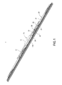
FIG. 1 is a perspective view showing the external appearance of the windshield wiper of the present invention;
FIG. 2 is an exploded perspective view showing the windshield wiper of the present invention;
FIG. 3 is an exploded perspective view showing the auxiliary wiper frames and the connecting frames of the present invention;
FIG. 4 is a perspective view showing the external appearance when the auxiliary wiper frames and the connecting frames of the present invention are assembled together;
FIG. 5 is an assembled cross-sectional view showing the windshield wiper of the present invention;
FIG. 6 is another assembled cross-sectional view showing the windshield wiper of the present invention; and
FIG. 7 is a schematic view showing the application of the windshield wiper of the present invention;
FIG. 8 is a perspective view showing the external appearance of the second embodiment of the windshield wiper of the present invention;
FIG. 9 is an exploded perspective view showing the windshield wiper of the second embodiment of the present invention;
FIG. 10 is an exploded perspective view showing another embodiment of auxiliary wiper frames and another connecting frames of the present invention;
FIG. 11 is a perspective view showing the external appearance when the auxiliary wiper frames and the connecting frames of FIG. 8 of the present invention are assembled together; and
FIG. 12 is an assembled cross-sectional view showing the windshield wiper of FIG. 9 of the present invention.
DETAILED DESCRIPTION OF THE INVENTION
The detailed description and technical contents of the present invention will become apparent with the following detailed description accompanied with related drawings. It is noteworthy to point out that the drawings is provided for the illustration purpose only, but not intended for limiting the scope of the present invention.
Please refer to FIG. 1 and FIG. 2. FIG. 1 is a perspective view showing the external appearance of the windshield wiper of the present invention, and FIG. 2 is an exploded perspective view showing the windshield wiper of the present invention. The present invention provides a windshield wiper with an even pressing force, which includes a primary wiper frame 10, a pair of auxiliary wiper frames 20, a plurality of connecting frames 30, and a wiper blade 40.
The primary wiper frame 10 comprises a fixing base 11. The fixing base 11 has a pivotal shaft 110. In the present embodiment, the primary wiper frame 10 further includes a set of fixing arms 12 connected to both sides of the fixing base 11. Each fixing arm 12 is provided with a first pivotal hole 120.
The pair of auxiliary wiper frames 20 is provided on both ends of the primary wiper frame 10, respectively. Each of the auxiliary wiper frames 20 comprises an elastic piece 21, a pivotal base 22 fixed to the elastic piece 21, and a set of rods 23. The elastic piece 21 is made by metallic materials and has elasticity for deformation. The pivotal base 22 is pivotally connected to the primary wiper frame 10. In the present embodiment, the pivotal base 22 is connected to the fixing arm 12. Each rod 23 is disposed through the pivotal base 22 and the fixing arm 12, so that the pair of auxiliary wiper frames 20 can be connected to the fixing arms 12. In the present embodiment, the pivotal base 22 is provided with a second pivotal hole 220 corresponding to the first pivotal hole 120. The rod 23 is disposed through the first pivotal hole 120 and the second pivotal hole 220, thereby connecting the pair of auxiliary wiper frames 20 to the fixing arms 12.
The connecting frames 30 are evenly disposed on each auxiliary wiper frame 20. Each of the auxiliary wiper frames 20 is provided with the same number of connecting frames 30. In the present embodiment, each of the auxiliary wiper frames 20 is provided with two connecting frames 30 (not limited thereto). The two connecting frames 30 are provided on both ends of the auxiliary wiper frame 20 respectively. Each of the connecting frames 30 comprises a pressing piece 31 and a plurality of buckling brackets 32 provided on the pressing piece 31. The wiper blade 40 is made of rubber. The wiper blade 40 is disposed through the buckling brackets 32 and connected below the pressing pieces 31.
Please refer to FIGS. 3 to 6. FIG. 3 is an exploded perspective view showing the auxiliary wiper frames and the connecting frames of the present invention. FIG. 4 is a perspective view showing the external appearance when the auxiliary wiper frames and the connecting frames of the present invention are assembled together. FIG. 5 is an assembled cross-sectional view showing the windshield wiper of the present invention. FIG. 6 is another assembled cross-sectional view showing the windshield wiper of the present invention. The pivotal base 22 of the auxiliary wiper frame 20 comprises a first connecting base 221 and a second connecting base 222 connected to both sides of the elastic piece 21. The first connecting base 221 and the second connecting base 222 are provided with a second pivotal hole 220 respectively for allowing the rod 23 to pass through. The first connecting base 221 is provided with a first through-hole 2210, and the second connecting base 222 is provided with a second trough 2220. The first connecting base 221 and the second connecting base 222 are positioned on both sides of the elastic piece 21 by means of the first through-hole 2210 and the second through-hole 2220. Then, the rod 23 is disposed into the second pivotal hole 220, so that the pivotal base 22 can be pivotally connected to the bottom surface of the fixing arm 12.
The assembly of the connecting frame 30 will be described more specifically as follows. The pressing piece 31 is formed into an arc shape, so that the middle portion of the pressing piece 31 is positioned at a level higher that of both sides of the pressing piece 31. The buckling bracket 32 comprises a U-shaped frame 321 and a set of restricting pieces 322 formed inside the U-shaped frame 321. The wiper blade 40 is slidingly connected to the inside of the restricting piece 322. The wiper blade 40 comprises a fixing section 41 and a wiping section 42 connected to the fixing section 41. The fixing section 41 is disposed through the U-shaped frame 321 along the restricting pieces 322. The wiping piece 42 is exposed to the outside of the U-shaped frame 321, thereby connecting the wiping blade 40 to the connecting frames 30.
Further, the connecting frame 30 comprises a plurality of positioning blocks 33. The elastic piece 21 is provided with a plurality of first troughs 210. Each of the pressing pieces 31 is provided with a second trough 310. The positioning block 33 is disposed through the second trough 310 to abut in the first trough 210, thereby fixing the connecting frame 30 to the bottom surface of the elastic piece 21.
Please refer to FIG. 7, which is a schematic view showing the application of the windshield wiper of the present invention. The wiper blade 1 is connected to a driving arm 2. The driving arm 2 is fixed to the pivotal shaft 110 of the primary wiper frame 10, so that the driving arm 2 can drive the windshield wiper 1. Further, a protective sheath 50 is put outside the windshield wiper 1 for protection purpose.
Please refer to FIG. 8 and FIG. 9. FIG. 8 is a perspective view showing the external appearance of the second embodiment of the windshield wiper of the present invention, and FIG. 9 is an exploded perspective view showing the windshield wiper of the second embodiment of the present invention. In the present embodiment, a windshield wiper 1 a includes a primary wiper frame 10 a, a pair of auxiliary wiper frames 20 a, a plurality of connecting frames 30 a, and a wiper blade 40 a. The primary wiper frame 10 a comprises a fixing base 11 a and a set of fixing arms 12 a connected to both sides of the fixing base 11 a. Each fixing arm 12 a is provided with a first pivotal hole 120 a.
The pair of auxiliary wiper frames 20 a is provided on both ends of the primary wiper frame 10 a, respectively. Each of the auxiliary wiper frames 20 a comprises an elastic piece 21 a, a pivotal base 22 a fixed to the elastic piece 21 a, and a set of rods 23 a. The pivotal base 22 a is pivotally connected to the primary wiper frame 10 a. In the present embodiment, the pivotal base 22 a is connected to the fixing arm 12 a. In the present embodiment, the pivotal base 22 a is provided with a second pivotal hole 220 a corresponding to the first pivotal hole 120 a. The rod 23 a is disposed through the first pivotal hole 120 a and the second pivotal hole 220 a, thereby connecting the pair of auxiliary wiper frames 20 a to the fixing arms 12 a. The present embodiment is different from the first embodiment in that the pivotal base 22 a is integrally formed with the elastic piece 21 a, and the connecting frames 30 a are evenly riveted on each auxiliary wiper frame 20 a.
Please also refer to FIGS. 10 to 12. FIG. 10 is an exploded perspective view showing the second embodiment of auxiliary wiper frames and the connecting frames of the present invention. FIG. 11 is a perspective view showing the external appearance when the auxiliary wiper frames and the connecting frames of FIG. 10 of the present invention are assembled together. FIG. 12 is an assembled cross-sectional view showing the windshield wiper of FIG. 11 of the present invention. In the present embodiment, each of the connecting frames 30 a comprises a pressing piece 31 a, a plurality of buckling brackets 32 a provided on the pressing piece 31 a, a rivet base 33 a riveted to the elastic piece 31 a, a rivet sheath 34 a and a rivet 35 a. The rivet base 33 a is riveted to the elastic piece 21 a through the rivet 35 a. The wiper blade 40 a is disposed through the buckling brackets 32 a and connected below the pressing pieces 31 a. The pressing piece 31 a is formed into an arc shape, so that the middle portion of the pressing piece 31 a is positioned at a level higher that of both sides of the pressing piece 31 a. The wiper blade 40 a is slidingly connected to the inside of the buckling brackets 32 a.
Moreover, each of the pressing pieces 31 a is provided with a positioning hole 310 a, and the rivet sheath 34 a is correspondingly provided with a positioning shaft 341 a. The rivet sheath 34 a is combined with the pressing pieces 31 a through the positioning shaft 341 a positioned in the positioning hole 310 a. In the present embodiment, the rivet sheath 34 a has a fixing protrusion 342 a, and the rivet base 33 a has an extended cover 331 a and a fixing hole 330 a provided on the extended cover 331 a. Then the pressing pieces 31 a will be combined to the elastic piece 21 a of the auxiliary wiper frame 20 a through the rivet sheath 34 a connecting with the rivet base 33 a. The extended cover 331 a of the rivet base 33 a covers the rivet sheath 34 a, and the fixing protrusion 342 a is located in the fixing hole 330 a. Thus the rivet sheath 34 a and the rivet base 33 a are connected together.
Although the present invention has been described with reference to the foregoing preferred embodiment, it will be understood that the invention is not limited to the details thereof. Various equivalent variations and modifications can still occur to those skilled in this art in view of the teachings of the present invention. Thus, all such variations and equivalent modifications are also embraced within the scope of the invention as defined in the appended claims.