US9295833B2 - Implantable medical lead - Google Patents
Implantable medical lead Download PDFInfo
- Publication number
- US9295833B2 US9295833B2 US11/914,050 US91405005A US9295833B2 US 9295833 B2 US9295833 B2 US 9295833B2 US 91405005 A US91405005 A US 91405005A US 9295833 B2 US9295833 B2 US 9295833B2
- Authority
- US
- United States
- Prior art keywords
- lead
- conductor
- polymeric tube
- sensor
- surface layer
- Prior art date
- Legal status (The legal status is an assumption and is not a legal conclusion. Google has not performed a legal analysis and makes no representation as to the accuracy of the status listed.)
- Active, expires
Links
- 239000004020 conductor Substances 0.000 claims abstract description 134
- 239000002344 surface layer Substances 0.000 claims abstract description 38
- 238000009825 accumulation Methods 0.000 claims abstract description 10
- 230000000694 effects Effects 0.000 claims abstract description 9
- OKTJSMMVPCPJKN-UHFFFAOYSA-N Carbon Chemical compound [C] OKTJSMMVPCPJKN-UHFFFAOYSA-N 0.000 claims description 15
- 239000000463 material Substances 0.000 claims description 15
- 239000011248 coating agent Substances 0.000 claims description 13
- 238000000576 coating method Methods 0.000 claims description 13
- 229910002804 graphite Inorganic materials 0.000 claims description 10
- 239000010439 graphite Substances 0.000 claims description 10
- 239000010410 layer Substances 0.000 claims description 8
- 229920001940 conductive polymer Polymers 0.000 claims description 7
- 230000001050 lubricating effect Effects 0.000 claims description 6
- 239000000843 powder Substances 0.000 claims description 6
- 229910052799 carbon Inorganic materials 0.000 claims description 4
- 238000002513 implantation Methods 0.000 claims description 4
- 229910052751 metal Inorganic materials 0.000 claims description 4
- 239000002184 metal Substances 0.000 claims description 4
- 229910052783 alkali metal Inorganic materials 0.000 claims description 3
- 150000001340 alkali metals Chemical class 0.000 claims description 3
- 239000003575 carbonaceous material Substances 0.000 claims description 3
- WHXSMMKQMYFTQS-UHFFFAOYSA-N Lithium Chemical compound [Li] WHXSMMKQMYFTQS-UHFFFAOYSA-N 0.000 claims description 2
- ZLMJMSJWJFRBEC-UHFFFAOYSA-N Potassium Chemical compound [K] ZLMJMSJWJFRBEC-UHFFFAOYSA-N 0.000 claims description 2
- 239000000571 coke Substances 0.000 claims description 2
- 150000001875 compounds Chemical class 0.000 claims description 2
- 229910052744 lithium Inorganic materials 0.000 claims description 2
- 229910044991 metal oxide Inorganic materials 0.000 claims description 2
- 150000004706 metal oxides Chemical class 0.000 claims description 2
- 229910052700 potassium Inorganic materials 0.000 claims description 2
- 239000011591 potassium Substances 0.000 claims description 2
- 239000004071 soot Substances 0.000 claims description 2
- 230000002687 intercalation Effects 0.000 claims 1
- 238000009830 intercalation Methods 0.000 claims 1
- 230000000747 cardiac effect Effects 0.000 description 39
- 230000033001 locomotion Effects 0.000 description 14
- 238000000034 method Methods 0.000 description 11
- 210000001519 tissue Anatomy 0.000 description 11
- 230000000638 stimulation Effects 0.000 description 10
- 210000004369 blood Anatomy 0.000 description 5
- 239000008280 blood Substances 0.000 description 5
- 230000004936 stimulating effect Effects 0.000 description 5
- 229920000642 polymer Polymers 0.000 description 4
- 229920002379 silicone rubber Polymers 0.000 description 4
- 239000004945 silicone rubber Substances 0.000 description 4
- 230000008859 change Effects 0.000 description 3
- 238000010586 diagram Methods 0.000 description 3
- 238000012986 modification Methods 0.000 description 3
- 230000004048 modification Effects 0.000 description 3
- 229920003225 polyurethane elastomer Polymers 0.000 description 3
- RTAQQCXQSZGOHL-UHFFFAOYSA-N Titanium Chemical compound [Ti] RTAQQCXQSZGOHL-UHFFFAOYSA-N 0.000 description 2
- 210000004204 blood vessel Anatomy 0.000 description 2
- 210000004903 cardiac system Anatomy 0.000 description 2
- 238000004891 communication Methods 0.000 description 2
- 238000010292 electrical insulation Methods 0.000 description 2
- 238000012544 monitoring process Methods 0.000 description 2
- BASFCYQUMIYNBI-UHFFFAOYSA-N platinum Chemical compound [Pt] BASFCYQUMIYNBI-UHFFFAOYSA-N 0.000 description 2
- 239000004814 polyurethane Substances 0.000 description 2
- 229910052719 titanium Inorganic materials 0.000 description 2
- 239000010936 titanium Substances 0.000 description 2
- 206010003658 Atrial Fibrillation Diseases 0.000 description 1
- KJTLSVCANCCWHF-UHFFFAOYSA-N Ruthenium Chemical compound [Ru] KJTLSVCANCCWHF-UHFFFAOYSA-N 0.000 description 1
- 208000001871 Tachycardia Diseases 0.000 description 1
- NRTOMJZYCJJWKI-UHFFFAOYSA-N Titanium nitride Chemical compound [Ti]#N NRTOMJZYCJJWKI-UHFFFAOYSA-N 0.000 description 1
- QCWXUUIWCKQGHC-UHFFFAOYSA-N Zirconium Chemical compound [Zr] QCWXUUIWCKQGHC-UHFFFAOYSA-N 0.000 description 1
- 230000001133 acceleration Effects 0.000 description 1
- 229910045601 alloy Inorganic materials 0.000 description 1
- 239000000956 alloy Substances 0.000 description 1
- 230000004075 alteration Effects 0.000 description 1
- 125000003118 aryl group Chemical group 0.000 description 1
- 238000007664 blowing Methods 0.000 description 1
- 206010061592 cardiac fibrillation Diseases 0.000 description 1
- 210000000038 chest Anatomy 0.000 description 1
- 239000002322 conducting polymer Substances 0.000 description 1
- 239000011231 conductive filler Substances 0.000 description 1
- 230000003247 decreasing effect Effects 0.000 description 1
- 230000001419 dependent effect Effects 0.000 description 1
- 230000001627 detrimental effect Effects 0.000 description 1
- 238000011161 development Methods 0.000 description 1
- 239000002019 doping agent Substances 0.000 description 1
- 230000009977 dual effect Effects 0.000 description 1
- 230000002526 effect on cardiovascular system Effects 0.000 description 1
- 238000001125 extrusion Methods 0.000 description 1
- 230000002600 fibrillogenic effect Effects 0.000 description 1
- PCHJSUWPFVWCPO-UHFFFAOYSA-N gold Chemical compound [Au] PCHJSUWPFVWCPO-UHFFFAOYSA-N 0.000 description 1
- 229910052737 gold Inorganic materials 0.000 description 1
- 239000010931 gold Substances 0.000 description 1
- 210000002837 heart atrium Anatomy 0.000 description 1
- 210000005003 heart tissue Anatomy 0.000 description 1
- 239000007943 implant Substances 0.000 description 1
- 239000011810 insulating material Substances 0.000 description 1
- 238000009413 insulation Methods 0.000 description 1
- 229910052741 iridium Inorganic materials 0.000 description 1
- GKOZUEZYRPOHIO-UHFFFAOYSA-N iridium atom Chemical compound [Ir] GKOZUEZYRPOHIO-UHFFFAOYSA-N 0.000 description 1
- 230000009191 jumping Effects 0.000 description 1
- 238000004898 kneading Methods 0.000 description 1
- 210000005240 left ventricle Anatomy 0.000 description 1
- 239000000314 lubricant Substances 0.000 description 1
- 239000011159 matrix material Substances 0.000 description 1
- 238000005259 measurement Methods 0.000 description 1
- 239000002991 molded plastic Substances 0.000 description 1
- 229910052758 niobium Inorganic materials 0.000 description 1
- 239000010955 niobium Substances 0.000 description 1
- GUCVJGMIXFAOAE-UHFFFAOYSA-N niobium atom Chemical compound [Nb] GUCVJGMIXFAOAE-UHFFFAOYSA-N 0.000 description 1
- 150000004767 nitrides Chemical class 0.000 description 1
- 229910052697 platinum Inorganic materials 0.000 description 1
- -1 polyanitine Polymers 0.000 description 1
- 229920000128 polypyrrole Polymers 0.000 description 1
- 229920000123 polythiophene Polymers 0.000 description 1
- 238000009877 rendering Methods 0.000 description 1
- 230000004044 response Effects 0.000 description 1
- 210000005241 right ventricle Anatomy 0.000 description 1
- 229910052707 ruthenium Inorganic materials 0.000 description 1
- 239000002904 solvent Substances 0.000 description 1
- 238000005507 spraying Methods 0.000 description 1
- 239000000725 suspension Substances 0.000 description 1
- 230000008961 swelling Effects 0.000 description 1
- 230000006794 tachycardia Effects 0.000 description 1
- 229910052715 tantalum Inorganic materials 0.000 description 1
- GUVRBAGPIYLISA-UHFFFAOYSA-N tantalum atom Chemical compound [Ta] GUVRBAGPIYLISA-UHFFFAOYSA-N 0.000 description 1
- 238000002560 therapeutic procedure Methods 0.000 description 1
- WFKWXMTUELFFGS-UHFFFAOYSA-N tungsten Chemical compound [W] WFKWXMTUELFFGS-UHFFFAOYSA-N 0.000 description 1
- 229910052721 tungsten Inorganic materials 0.000 description 1
- 239000010937 tungsten Substances 0.000 description 1
- 208000003663 ventricular fibrillation Diseases 0.000 description 1
- 229910052726 zirconium Inorganic materials 0.000 description 1
Images


Classifications
-
- A—HUMAN NECESSITIES
- A61—MEDICAL OR VETERINARY SCIENCE; HYGIENE
- A61N—ELECTROTHERAPY; MAGNETOTHERAPY; RADIATION THERAPY; ULTRASOUND THERAPY
- A61N1/00—Electrotherapy; Circuits therefor
- A61N1/02—Details
- A61N1/04—Electrodes
- A61N1/05—Electrodes for implantation or insertion into the body, e.g. heart electrode
- A61N1/056—Transvascular endocardial electrode systems
-
- A—HUMAN NECESSITIES
- A61—MEDICAL OR VETERINARY SCIENCE; HYGIENE
- A61N—ELECTROTHERAPY; MAGNETOTHERAPY; RADIATION THERAPY; ULTRASOUND THERAPY
- A61N1/00—Electrotherapy; Circuits therefor
- A61N1/18—Applying electric currents by contact electrodes
- A61N1/32—Applying electric currents by contact electrodes alternating or intermittent currents
- A61N1/36—Applying electric currents by contact electrodes alternating or intermittent currents for stimulation
- A61N1/362—Heart stimulators
- A61N1/365—Heart stimulators controlled by a physiological parameter, e.g. heart potential
- A61N1/36514—Heart stimulators controlled by a physiological parameter, e.g. heart potential controlled by a physiological quantity other than heart potential, e.g. blood pressure
- A61N1/36564—Heart stimulators controlled by a physiological parameter, e.g. heart potential controlled by a physiological quantity other than heart potential, e.g. blood pressure controlled by blood pressure
Definitions
- the present invention generally relates to the field of implantable medical devices. More specifically, the present invention relates to an implantable lead for sensing mechanical activity of a human heart, the lead comprising a first non-conductive polymeric tube extending from a proximal end to a distal end of said lead, a first conductor provided in a lumen of said first polymeric tube, and a sensor.
- piezo-resistive, piezocapacitive or piezoelectric sensors could be used for sensing mechanical properties, such as pressure changes in the heart or in other blood vessels.
- a piezoelectric sensor suitable for use as a pressure sensor is shown in WO 02/34130.
- tachycardias such as fibrillation
- Atrial fibrillation can be separated from ventricular fibrillation and electrical activity can be separated from mechanical activity. This is of importance for controlling the type of stimulation therapy to be delivered by a heart stimulator.
- rate responsive implanted cardiac stimulators a number of different parameters have been used for determining the activity level of the patient, which in turn is used for controlling the rate at which the heart of a patient is to be stimulated by the pacemaker.
- One of the most common sensors used is the piezoelectric accelerometer.
- piezoelectric sensors are advantageous in that they are not energy consuming.
- Piezoelectric sensors are arranged to alter the mechanical stress of the piezoelectric material in response to a change of loads emanating from for instance an acceleration of a seismic mass or from a change in pressure acting on the sensor. This results in a transport of electrons or electrical charges within the material, which provides a change in voltage across the piezoelectric sensor. This voltage corresponds to the load to which the sensor is subjected.
- changes for instance in pressure acting on the sensor can be monitored.
- a piezoelectric sensor such as a pressure sensor or an accelerometer
- the voltage signal produced by the sensor is affected by motion artifacts.
- Such motion artifacts can be due to movements of the patient, i.e. jumping, running, etc., or the motions of the heart and the thorax during their regular cardiovascular operation.
- the motion artifacts could be large enough to disturb a sensor signal, especially when using a piezoelectric pressure sensor since the voltage changes produced by the piezoelectric sensor from pressure changes are very small.
- it could be difficult to separate the contribution of the motion artifacts from the useful signal contribution from pressure changes.
- the interpretation of the sensor signal could be rendered difficult or even impossible.
- An object of the present invention is to provide a solution to the abovementioned problem of the detrimental contribution from motion artifacts to sensor signals.
- an implantable lead for sensing mechanical activity of a human heart having a first non-conductive polymeric tube extending from a proximal end to a distal end of the lead, a first conductor provided in a lumen of the first polymeric tube, and a sensor connected to the first conductor at a distal end thereof. Furthermore, the first polymeric tube is provided with a conductive inner surface layer, so as to prevent accumulation of electrical charges between said first conductor and said first polymeric tube.
- the present invention is based on the advantageous idea of providing the cardiac lead connecting an intracardiac sensor to an implantable medical device, such as a cardiac stimulator, with electrically insulating tubing having an electrically conductive surface layer facing and contacting the conductor.
- a charge amplifier When using a sensor in which changes in the sensed properties, e.g. pressure, give rise to small changes in voltage across the sensor, a charge amplifier operates to maintain the voltage across the sensor at a constant level, e.g. at 0 V, by receiving the electrical charges emitted by the sensor. As a result, the charge amplifier produces a voltage signal which is directly dependent on the amount of charges received from the sensor.
- a cardiac stimulator such a charge amplifier is positioned within the housing or the can of the cardiac stimulator, and a cardiac lead connects the sensor to the housing and the charge amplifier.
- the voltage which the charge amplifier maintains at a constant level is that provided over the sensor and the conductor or conductors connecting the sensor to the charge amplifier.
- the senor In a one conductor system, the sensor is connected between the conductor and ground, and in a two conductor system, the sensor is connected in series with the two conductors contained within the cardiac lead.
- the charge amplifier produces a voltage signal resulting from the transport of charges over the sensor, as well as any accumulation of electrical charges in the single conductor, or in the two conductors.
- the senor in a sense is still connected in series to the charge amplifier.
- it is an electrically conducting portion of the stimulator housing that is electrically connected to the charge amplifier.
- the sensor is then connected, on the one hand, to the conductor within the cardiac lead, and, on the other hand, to the stimulator housing via human tissue and blood surrounding the sensor and the stimulator.
- the tissue and blood acts as a conductor between the charge amplifier and the sensor.
- the cardiac lead comprises a conductor arranged within the lumen of a polymeric tube, which covers the conductor from end to end and provides electrical insulation of the conductor, in particular from surrounding tissue.
- the inner surface of the tube which is in contact with the conductor is provided with an electrically conductive layer, such that the conductor is not in direct contact with the electrically insulating portions of the tube.
- the conductor is preferably helically wound within the polymeric tube.
- the cardiac lead comprises a second conductor arranged around the first polymeric tube, such that the first polymeric tube provides electric insulation between the two conductors.
- the conductors and the first tube is arranged within the lumen of a second polymeric tube which is provided for covering both conductors and the first tube, and for providing electrical insulation of the conductors, in particular from surrounding tissue.
- the conductors and the polymeric tubes are preferably co-axially arranged.
- each conductor is preferably helically wound within the respective tube.
- the outer surface thereof in addition to the inner surface layer of the first, inner tube being provided with an electrically conductive surface layer, the outer surface thereof, i.e. facing and contacting the outer conductor, is preferably provided with an electrically conductive surface layer. Furthermore, the inner surface of the second, outer tube, i.e. also facing and contacting the outer conductor, is preferably provided with an electrically conductive surface layer.
- all surfaces of the polymeric tube in contact with the two conductors are provided with electrically conductive surface layers. Thus, no portion of the conductors are in direct contact with an electrically insulating portion of the polymeric tube, and there will be no accumulation of electrical charges due to motion artifacts along the interfaces between the conductors and the tube.
- the polymeric tubing is in the form of a single tube provided with a plurality of longitudinally extending conductor lumina or lumens with axes arranged in parallel, each lumen being arranged for covering and electrically insulating a conductor.
- the surface of each lumen facing and contacting a conductor connected to a sensor is provided with an electrically conductive surface layer.
- the multiple lumina are arranged at the same diameter of the lead, circumferentially spaced apart at regular angular intervals.
- a centrally arranged lumen can be provided, i.e. running along the axial centre of the cardiac lead.
- a single lead preferably comprises two to four circumferentially spaced lumina, and one centrally arranged lumen.
- the conductors contained in each lumen are preferably not helically wound, but rather in the form of essentially straight, multi strand wires.
- tubes having a plurality of parallel lumina are also contemplated within the scope of the present application, for instance lumina having different diameters within the same tubing, having noncircular cross-sections, or being provided at different diameters within a single tubing.
- a tubing could be provided with two smaller and one larger lumina, wherein none of the axes the lumina coincides with the axis of the tubing.
- one conductor systems and two conductor systems only refers to the number of conductors connecting a sensor to electronic circuitry within a housing of a medical implant.
- a lead for a one conductor system or for a two conductor system could be provided with further conductors that are not connected to a sensor.
- the polymeric tubing is a co-extrusion of a non-conductive, insulating portion and at least one conductive surface layer portion.
- the insulating portion and the conducting portion or portions are co-axially arranged.
- the conductive portion of the coextrusion could be provided by mixing an electrically conductive powder or the like in a polymeric material, thus co-extruded.
- a powder could comprise a metal, preferably a biocompatible metal, such as titanium, platinum, gold, niobium, iridium, ruthenium, tungsten, zirconium, or tantalum, or alloys thereof, or conductive metal oxides or nitrides, such as titanium nitride.
- Other examples include carbonaceous materials, such as graphite, coke, soot, or compounds of carbon intercalated with alkali metals, such as lithium or potassium.
- the insulating polymer could be co-extruded with another, electrically conductive polymer, which makes up the conductive surface portions of the tubing.
- conducting polymers include polyacetonitrile (PAN), and poly-mercaptanes.
- the conductive polymer can be a polymer having conjugated double bonds, or aromatic rings, that permit transport of electrons through the polymer, thereby rendering the polymer conductive, possibly with the further addition of a suitable dopant, such as polypyrrole, polyanitine, or polythiophene.
- Other examples of conductive polymers include a non-conductive polymeric matrix provided with a conductive filler material.
- a polymeric, insulating tubing is provided with at least one electrically conducting coating constituting the respective electrically conductive surface layer.
- a coating could be obtained by applying a solution comprising an electrically conductive material onto the tubing, for example by spraying the solution onto the surface of the polymeric tubing, submerging the polymeric tubing in the solution, etc.
- the solution could be a powder (see above for examples) in suspension, a conductive polymer in a solvent etc. As the solution dries, the conductive material adheres to the surface of the tubing, thereby providing said electrically conductive surface coating of the tubing.
- Further examples involve providing a coating by blowing an electrically conductive powder onto the surface of the tubing, by rubbing an electrically conducting material onto the tubing.
- a tubing having an electrically conducting coating is formed.
- the conductive material could be mechanically worked into the surface of the tubing, such as by kneading or squeezing the tubing through a mangle.
- the tubing could be expanded by swelling prior to applying the coating in order to enhance the adhesion between the coating and the surface of the tubing.
- the surface of the tubing could be heated after application of the coating in order to enhance the adhesion between the coating and the tubing.
- the conductive surface layer of the polymeric tubing is further arranged to have a lubricating effect. Due to the continued efforts in decreasing the cross-section dimensions of cardiac leads, along with development of new materials for the polymeric tubing with increased adhering properties, cardiac leads become increasingly difficult to assemble. By providing the conductive surface layer of the polymeric tubing with lubricating properties, the frictional force between the polymeric tubing and the conductors could be significantly reduced.
- the surface layer of the tubing comprises graphite, which has both lubricating and conductive properties.
- suitable materials having both lubricating and conducting properties could be used without departing from the scope of the present invention, in particular the carbonaceous materials mentioned herein.
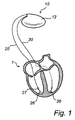
- FIG. 1 is a simplified, partly cutaway view illustrating an implantable stimulation device in electrical communication via cardiac leads with a human heart.
- FIG. 2 a is a longitudinal cross-section view of an electrode lead according to one embodiment of the invention.
- FIG. 2 b is a transversal cross-section view of the electrode lead shown in FIG. 2 a.
- FIG. 3 is a transversal cross-section view of an electrode lead according to a further embodiment of the invention.
- FIG. 4 is a schematical circuit diagram illustrating a system wherein a sensor is connected to a charge amplifier via one conductor in the electronic lead.
- FIG. 5 is a schematical circuit diagram illustrating an alternative system with a sensor connected to a charge amplifier via two conductors within the electronic lead.
- the following is a description of preferred embodiments in accordance with the present invention. This description is intended for describing the general principles of the invention and is not to be taken in a limiting sense. Thus, even though a biventricular heart stimulator for sensing and stimulating in both ventricles is being illustrated, the invention is also applicable to heart stimulators arranged for sensing and stimulating in one ventricle only, and/or for stimulating in the atria of a human heart. Furthermore, the invention is also applicable to implantable cardioverter-defibrillators (ICD).
- ICD implantable cardioverter-defibrillators
- an implantable heart stimulator 10 in electrical communication with a human heart 1 via two cardiac leads 20 , 30 arranged for stimulation and sensing.
- the heart stimulator 10 comprises electronic circuitry and a battery contained within a hermetically sealed pacemaker housing 12 .
- the housing 12 has a metallic casing of titanium, enclosing the electronic circuitry and battery, and a molded plastic header, comprising connector blocks and apertures for receiving the connectors at the proximal ends of the cardiac leads.
- the header is attached to the metallic casing in a fixed and sealed arrangement.
- the electronic circuitry comprises at least one pulse generator for generating stimulation pulses, sensing circuitry for receiving cardiac signals sensed by the cardiac leads 20 , 30 , and a controller.
- the controller controls both the sensing of cardiac signals and the delivery of stimulation pulses, for instance as to the duration, energy content and timing of the stimulation pulses.
- the stimulation pulses generated by the pulse generator are transmitted via the cardiac leads 20 , 30 and delivered to the cardiac tissue of the left and right ventricles of the heart, respectively, by the use of tip electrodes 26 , 36 .
- the tip electrode 26 , 36 acts as the cathode when the cardiac pulse is delivered.
- the casing 12 acts as the anode, while in bipolar cardiac systems, the anode is provided by an annular electrode (not shown) arranged on the cardiac lead at a small distance from the tip electrode. It should be noted that even though no annular or ring electrode is illustrated in the greatly simplified drawing of FIG. 1 , the present invention is equally applicable to unipolar and bipolar systems.
- FIGS. 2 a and 2 b there is shown an implantable lead 20 in accordance with a preferred embodiment of the present invention.
- the lead 20 has an inner conductor 21 and an outer conductor 22 , both in the form of helical coils.
- the inner conductor 21 is connected to the tip electrode 26 and the outer conductor 22 is connected to a piezoelectric pressure sensor 27 , which will be described further below.
- the two conductors 21 , 22 are coaxially arranged and separated by a flexible inner tubing 23 made of an electrically insulating polymeric material, which in the preferred embodiments is silicone rubber or polyurethane rubber (PUR).
- PUR polyurethane rubber
- an outer tubing 24 is co-axially arranged about the outer conductor 22 for separating and insulating the outer conductor 22 from surrounding tissue 2 , generally blood.
- an electrically insulating sleeve 28 is arranged between the sensor 27 and the tip electrode in order to provide the distal portion of the lead 20 with a uniform diameter.
- the outer tubing 24 and the distal sleeve 28 is also made of silicone rubber or PUR.
- the surfaces of the inner tubing 23 and the outer tubing 24 facing the inner and outer conductors 21 , 22 , respectively, are provided with electrically conductive surface layers 25 .
- the electrically conducting layers 25 are provided by coating the corresponding surfaces of the polymeric tubing 23 , 24 with graphite.
- the graphite layer is provided as a graphite powder.
- the graphite layers 25 are provided prior to assembling the cardiac lead.
- the graphite also has lubricant properties. Thereby, the friction between the tubing 23 , 24 and the conductors 21 , 22 is reduced, which inter alia facilitates the assembly of the cardiac lead 20 , in particular when the conductors are fed into and through the lumen of the cardiac lead during assembly thereof.
- the cardiac lead 20 has two helically wound conductors 21 , 22 .
- the lead 20 is a unipolar lead. This is due to the fact that the term “unipolar” only refers to the electrodes or “poles” that are being used for the delivery of cardiac pulses.
- the outer conductor 22 is arranged for transmitting electrical signals between the pressure sensor 27 and the heart stimulator 10 , and not for delivering stimulation pulses to an electrode positioned in the human heart. Accordingly, in the presently described embodiment, there is only one stimulating electrode 26 located in the human heart and the disclosed lead is a unipolar lead.
- the invention is of course not limited to unipolar leads.
- the cardiac lead could be provided with further conductors connected to further sensors and/or stimulating electrodes.
- a further conductor connected to a ring electrode provided for delivering stimulation pulses is contemplated.
- the pressure sensor 27 is coaxially arranged about the inner tubing 23 distally of the outer conductor 22 , which is connected to the sensor 27 via a sensor electrode (not shown) provided on the sensor.
- the sensor 27 is a piezoelectric pressure sensor of the type shown in the International application published under No. WO 02/34130, which hereby is incorporated herein by reference.
- the sensor 27 comprises a piezoelectric element disposed coaxially around a rigid supporting structure. Changes in pressure acting on the piezoelectric sensor 27 results in transport of electrical charges across the sensor, which would cause small changes in the voltage across the sensor. However, since the sensor 27 is connected to a charge amplifier 14 , contained within the stimulator housing 12 , these charges are conducted to the charge amplifier 14 .
- the charge amplifier 14 absorbs the charges and keeps the voltage across the sensor 27 constant. Furthermore, the charge amplifier 14 outputs a voltage signal corresponding to the transported charges.
- two conductors electrically insulated from each other, are connected to electrodes provided on the sensor and to the inputs of the voltage amplifier.
- a first electrode (not shown) of the sensor is connected to the outer conductor 22 of the cardiac lead 20 . Furthermore, a second electrode (not shown) of the sensor 27 is electrically connected via the sleeve 28 to the tip electrode 26 , and thereby to the inner conductor 21 .
- the inner conductor 21 is arranged for transmitting stimulation pulses from the stimulator 10 to the tip electrode 26 , as well as for transmitting electrical signals from the sensor 27 to the stimulator 10 .
- the sleeve 28 is provided with an electrical conductor, connecting the tip electrode with the sensor electrode, and insulated from the surrounding tissue.
- the sensor 27 is provided with an outer silicone rubber layer in order to insulate the sensor 27 from the surrounding tissue 2 , in particular the electrodes of the sensor 27 . This embodiment will be further described below in relation to FIG. 5 .
- the sleeve 28 is merely made in an insulating material, ensuring that there is no electrical connection between the sensor 27 and the tip electrode 26 .
- a circumferential electrode facing the surrounding tissue must be provided in a material which is biocompatible. This embodiment will be further described below in relation to FIG. 4 .
- the cardiac lead 40 comprises a silicone rubber tubing 44 provided with a plurality of circumferentially spaced lumina 41 , as well as a central lumen 43 arranged at the axial centre of the lead 40 .
- the central lumen 43 is arranged for receiving a guide wire or stylet, which is used for guiding and controlling the cardiac lead during implantation thereof. Following implantation, the guide wire is removed from the cardiac lead.
- one of the circumferentially arranged lumina 41 could be used for receiving a guide wire.
- conductors 42 are provided within the circumferentially arranged lumina 41 , wherein two of the conductors 42 are connected to a pressure sensor 27 .
- the surfaces of the lumina 41 are provided with electrically conducting surface layers 45 .
- the surface layers 45 are provided by coating the tubing surfaces with graphite. Thereby, the friction between the conductors 42 and the tubing 44 is reduced and assembly of the lead is facilitated in the manner as described above.
- FIGS. 4 and 5 there is illustrated in simplified form a circuit diagram of the charge amplifier and the sensor.
- the system comprises a piezoelectric pressure sensor 27 , a conductor 22 located within a cardiac lead, and a charge amplifier 14 .
- One input of the charge amplifier 14 is connected via the conductor 22 to a first electrode of the sensor 27 .
- the other input of the charge amplifier 14 is connected to a second electrode of the sensor 27 , via a metallic, electrically conducting portion of the stimulator housing 12 and intervening blood and tissue.
- the respective inputs to the charge amplifier 14 are connected across the sensor 27 .
- changes in pressure acting upon the sensor results in transport of electrical charges across the sensor 27 .
- the charge amplifier 14 receives the transported charges, maintains the voltage across the sensor at a constant level, and outputs an amplified voltage signal corresponding to the transport of charges and variations in pressure to control circuitry.
- FIG. 5 a two conductor system is illustrated. This system corresponds to the system illustrated in FIG. 4 , except for the fact that the inputs of the charge amplifier 14 are both connected to the sensor 27 via conductors 21 , 22 , respectively, located within the cardiac lead. Thus, the charge amplifier 14 operates in similar manner to output a voltage signal corresponding to pressure changes acting on the piezoelectric pressure sensor 27 .
- the material for providing the electrical conductivity of the surface layers is by no means limited to graphite. A variety of suitable materials are contemplated within the scope of the present invention. Moreover, different materials could be used for the different surfaces within the same cardiac lead.
Landscapes
- Health & Medical Sciences (AREA)
- Heart & Thoracic Surgery (AREA)
- Cardiology (AREA)
- Life Sciences & Earth Sciences (AREA)
- General Health & Medical Sciences (AREA)
- Engineering & Computer Science (AREA)
- Biomedical Technology (AREA)
- Nuclear Medicine, Radiotherapy & Molecular Imaging (AREA)
- Radiology & Medical Imaging (AREA)
- Animal Behavior & Ethology (AREA)
- Hematology (AREA)
- Public Health (AREA)
- Veterinary Medicine (AREA)
- Biophysics (AREA)
- Physiology (AREA)
- Vascular Medicine (AREA)
- Electrotherapy Devices (AREA)
Abstract
Description
Claims (22)
Applications Claiming Priority (1)
| Application Number | Priority Date | Filing Date | Title |
|---|---|---|---|
| PCT/SE2005/000829 WO2006130056A1 (en) | 2005-05-31 | 2005-05-31 | Implantable lead |
Publications (2)
| Publication Number | Publication Date |
|---|---|
| US20090125090A1 US20090125090A1 (en) | 2009-05-14 |
| US9295833B2 true US9295833B2 (en) | 2016-03-29 |
Family
ID=37481896
Family Applications (1)
| Application Number | Title | Priority Date | Filing Date |
|---|---|---|---|
| US11/914,050 Active 2032-02-25 US9295833B2 (en) | 2005-05-31 | 2005-05-31 | Implantable medical lead |
Country Status (2)
| Country | Link |
|---|---|
| US (1) | US9295833B2 (en) |
| WO (1) | WO2006130056A1 (en) |
Cited By (1)
| Publication number | Priority date | Publication date | Assignee | Title |
|---|---|---|---|---|
| US12472329B2 (en) * | 2017-09-14 | 2025-11-18 | St. Jude Medical, Cardiology Division, Inc. | Torqueable steerable sheaths |
Families Citing this family (1)
| Publication number | Priority date | Publication date | Assignee | Title |
|---|---|---|---|---|
| US11890466B2 (en) | 2019-07-01 | 2024-02-06 | Wavegate Corporation | IPG and header combination |
Citations (11)
| Publication number | Priority date | Publication date | Assignee | Title |
|---|---|---|---|---|
| US4033355A (en) | 1975-11-28 | 1977-07-05 | Cardiac Pacemakers, Inc. | Electrode lead assembly for implantable devices and method of preparing same |
| US5330520A (en) | 1986-05-15 | 1994-07-19 | Telectronics Pacing Systems, Inc. | Implantable electrode and sensor lead apparatus |
| US5609622A (en) * | 1993-02-01 | 1997-03-11 | W. L. Gore & Associates, Inc. | Implantable electrode with conductive polytetrafluoroethylene elecrode |
| US5681514A (en) | 1995-06-07 | 1997-10-28 | Sulzer Intermedics Inc. | Method for making an implantable conductive lead for use with a cardiac stimulator |
| US5836946A (en) | 1996-06-12 | 1998-11-17 | The Spectranetics Corporation | Catheter for delivery of electric energy and a process for manufacturing same |
| WO2002034130A1 (en) | 2000-10-24 | 2002-05-02 | St. Jude Medical Ab | A piezoelectric sensor in a living organism for fluid pressure measurement. |
| US6564107B1 (en) | 2000-08-21 | 2003-05-13 | Cardiac Pacemakers, Inc. | Coil-less lead system |
| US20030181966A1 (en) | 2002-03-19 | 2003-09-25 | Morgan Kevin L. | Leads using composite materials for conductors and stylet insertion for improved handling characteristics in lead implantation performance |
| US20040068313A1 (en) | 2002-10-04 | 2004-04-08 | Jenney Christopher R. | Body implantable lead comprising electrically conductive polymer conductors |
| US6792309B1 (en) * | 1999-03-23 | 2004-09-14 | St. Jude Medical Ab | Multi-sensor system for controlling an implantable heart stimulator |
| US20040215300A1 (en) | 2003-04-23 | 2004-10-28 | Medtronic, Inc. | Electrical medical leads employing conductive aerogel |
-
2005
- 2005-05-31 WO PCT/SE2005/000829 patent/WO2006130056A1/en not_active Ceased
- 2005-05-31 US US11/914,050 patent/US9295833B2/en active Active
Patent Citations (11)
| Publication number | Priority date | Publication date | Assignee | Title |
|---|---|---|---|---|
| US4033355A (en) | 1975-11-28 | 1977-07-05 | Cardiac Pacemakers, Inc. | Electrode lead assembly for implantable devices and method of preparing same |
| US5330520A (en) | 1986-05-15 | 1994-07-19 | Telectronics Pacing Systems, Inc. | Implantable electrode and sensor lead apparatus |
| US5609622A (en) * | 1993-02-01 | 1997-03-11 | W. L. Gore & Associates, Inc. | Implantable electrode with conductive polytetrafluoroethylene elecrode |
| US5681514A (en) | 1995-06-07 | 1997-10-28 | Sulzer Intermedics Inc. | Method for making an implantable conductive lead for use with a cardiac stimulator |
| US5836946A (en) | 1996-06-12 | 1998-11-17 | The Spectranetics Corporation | Catheter for delivery of electric energy and a process for manufacturing same |
| US6792309B1 (en) * | 1999-03-23 | 2004-09-14 | St. Jude Medical Ab | Multi-sensor system for controlling an implantable heart stimulator |
| US6564107B1 (en) | 2000-08-21 | 2003-05-13 | Cardiac Pacemakers, Inc. | Coil-less lead system |
| WO2002034130A1 (en) | 2000-10-24 | 2002-05-02 | St. Jude Medical Ab | A piezoelectric sensor in a living organism for fluid pressure measurement. |
| US20030181966A1 (en) | 2002-03-19 | 2003-09-25 | Morgan Kevin L. | Leads using composite materials for conductors and stylet insertion for improved handling characteristics in lead implantation performance |
| US20040068313A1 (en) | 2002-10-04 | 2004-04-08 | Jenney Christopher R. | Body implantable lead comprising electrically conductive polymer conductors |
| US20040215300A1 (en) | 2003-04-23 | 2004-10-28 | Medtronic, Inc. | Electrical medical leads employing conductive aerogel |
Cited By (1)
| Publication number | Priority date | Publication date | Assignee | Title |
|---|---|---|---|---|
| US12472329B2 (en) * | 2017-09-14 | 2025-11-18 | St. Jude Medical, Cardiology Division, Inc. | Torqueable steerable sheaths |
Also Published As
| Publication number | Publication date |
|---|---|
| WO2006130056A1 (en) | 2006-12-07 |
| US20090125090A1 (en) | 2009-05-14 |
Similar Documents
| Publication | Publication Date | Title |
|---|---|---|
| US5545201A (en) | Bipolar active fixation lead for sensing and pacing the heart | |
| US5342414A (en) | Transvenous defibrillation lead | |
| US4444195A (en) | Cardiac lead having multiple ring electrodes | |
| US6263250B1 (en) | Ring electrode with porous member | |
| EP0769308B1 (en) | Implantable pacemaker lead | |
| US6701191B2 (en) | Lead having composite tubing | |
| US6104961A (en) | Endocardial defibrillation lead with looped cable conductor | |
| US6141594A (en) | Single pass lead and system with active and passive fixation elements | |
| US5871529A (en) | Electrode for high impedance heart stimulation | |
| US9119956B2 (en) | Medical electrodes with layered coatings | |
| US6253111B1 (en) | Multi-conductor lead | |
| US6606522B2 (en) | Torque mechanism and method for endocardial leads | |
| US7860581B2 (en) | Implantable lead with a stimulating electrode and a mapping electrode that is electrically disconnectable | |
| WO2008013908A1 (en) | Lead comprising electrode-shared drug region | |
| US12115380B2 (en) | Medical device with braided tubular body | |
| US6477428B1 (en) | Endocardial lead with vinylidene fluoride insulation | |
| US9295833B2 (en) | Implantable medical lead | |
| US8972025B2 (en) | Active fixation implantable medical lead | |
| US6374142B1 (en) | Isodiametric pacing/defibrillation lead | |
| EP4637910A1 (en) | Multi-electrode lead with elongated electrode | |
| US20050131507A1 (en) | Lead having reduced lead body size | |
| US20200060770A1 (en) | Electrode lead with integrated deformation sensor | |
| US20250099770A1 (en) | Implantable medical device and electrode thereof | |
| US20090326598A1 (en) | Pressure Sensing Lead Systems for Implantable Stimulators | |
| WO2025133669A1 (en) | Multi-level electrode |
Legal Events
| Date | Code | Title | Description |
|---|---|---|---|
| AS | Assignment |
Owner name: ST. JUDE MEDICAL AB, SWEDEN Free format text: ASSIGNMENT OF ASSIGNORS INTEREST;ASSIGNOR:NILSSON, KENTH;REEL/FRAME:021007/0938 Effective date: 20080213 |
|
| AS | Assignment |
Owner name: ST. JUDE MEDICAL AB, SWEDEN Free format text: ASSIGNMENT OF ASSIGNORS INTEREST;ASSIGNORS:NILSSON, KENTH;JOHANSSON, ANNA KARIN;ERIKSSON, TOM;REEL/FRAME:021750/0282;SIGNING DATES FROM 20081008 TO 20081022 Owner name: ST. JUDE MEDICAL AB, SWEDEN Free format text: ASSIGNMENT OF ASSIGNORS INTEREST;ASSIGNORS:NILSSON, KENTH;JOHANSSON, ANNA KARIN;ERIKSSON, TOM;SIGNING DATES FROM 20081008 TO 20081022;REEL/FRAME:021750/0282 |
|
| STCF | Information on status: patent grant |
Free format text: PATENTED CASE |
|
| MAFP | Maintenance fee payment |
Free format text: PAYMENT OF MAINTENANCE FEE, 4TH YEAR, LARGE ENTITY (ORIGINAL EVENT CODE: M1551); ENTITY STATUS OF PATENT OWNER: LARGE ENTITY Year of fee payment: 4 |
|
| MAFP | Maintenance fee payment |
Free format text: PAYMENT OF MAINTENANCE FEE, 8TH YEAR, LARGE ENTITY (ORIGINAL EVENT CODE: M1552); ENTITY STATUS OF PATENT OWNER: LARGE ENTITY Year of fee payment: 8 |