US9293632B2 - Pressure transfer process for thin film solar cell fabrication - Google Patents
Pressure transfer process for thin film solar cell fabrication Download PDFInfo
- Publication number
- US9293632B2 US9293632B2 US14/030,019 US201314030019A US9293632B2 US 9293632 B2 US9293632 B2 US 9293632B2 US 201314030019 A US201314030019 A US 201314030019A US 9293632 B2 US9293632 B2 US 9293632B2
- Authority
- US
- United States
- Prior art keywords
- workpiece
- rollers
- layer
- substrate
- pressure
- Prior art date
- Legal status (The legal status is an assumption and is not a legal conclusion. Google has not performed a legal analysis and makes no representation as to the accuracy of the status listed.)
- Expired - Fee Related
Links
- 238000000034 method Methods 0.000 title claims abstract description 218
- 239000010409 thin film Substances 0.000 title claims abstract description 52
- 238000004519 manufacturing process Methods 0.000 title description 82
- 238000012546 transfer Methods 0.000 title description 27
- 239000000463 material Substances 0.000 claims abstract description 205
- 239000000758 substrate Substances 0.000 claims abstract description 191
- 239000010949 copper Substances 0.000 claims abstract description 101
- 239000011669 selenium Substances 0.000 claims abstract description 80
- 239000006096 absorbing agent Substances 0.000 claims abstract description 64
- 238000003825 pressing Methods 0.000 claims abstract description 47
- 229910052717 sulfur Inorganic materials 0.000 claims abstract description 18
- 229910052711 selenium Inorganic materials 0.000 claims abstract description 10
- 239000011593 sulfur Substances 0.000 claims abstract description 10
- BUGBHKTXTAQXES-UHFFFAOYSA-N Selenium Chemical compound [Se] BUGBHKTXTAQXES-UHFFFAOYSA-N 0.000 claims abstract description 9
- 229910052738 indium Inorganic materials 0.000 claims abstract description 9
- 229910052802 copper Inorganic materials 0.000 claims abstract description 8
- NINIDFKCEFEMDL-UHFFFAOYSA-N Sulfur Chemical compound [S] NINIDFKCEFEMDL-UHFFFAOYSA-N 0.000 claims abstract description 7
- 229910052733 gallium Inorganic materials 0.000 claims abstract description 7
- RYGMFSIKBFXOCR-UHFFFAOYSA-N Copper Chemical compound [Cu] RYGMFSIKBFXOCR-UHFFFAOYSA-N 0.000 claims abstract description 6
- GYHNNYVSQQEPJS-UHFFFAOYSA-N Gallium Chemical compound [Ga] GYHNNYVSQQEPJS-UHFFFAOYSA-N 0.000 claims abstract description 6
- 150000004770 chalcogenides Chemical class 0.000 claims abstract description 6
- APFVFJFRJDLVQX-UHFFFAOYSA-N indium atom Chemical compound [In] APFVFJFRJDLVQX-UHFFFAOYSA-N 0.000 claims abstract description 6
- 238000000151 deposition Methods 0.000 claims description 86
- 230000008021 deposition Effects 0.000 claims description 67
- 238000001816 cooling Methods 0.000 claims description 48
- 238000010438 heat treatment Methods 0.000 claims description 42
- 238000004070 electrodeposition Methods 0.000 claims description 36
- 229910052751 metal Inorganic materials 0.000 claims description 34
- 239000002184 metal Substances 0.000 claims description 34
- 229910001220 stainless steel Inorganic materials 0.000 claims description 21
- 239000010935 stainless steel Substances 0.000 claims description 21
- 238000000137 annealing Methods 0.000 claims description 17
- 239000011521 glass Substances 0.000 claims description 14
- 239000000126 substance Substances 0.000 claims description 6
- ZOKXTWBITQBERF-UHFFFAOYSA-N Molybdenum Chemical compound [Mo] ZOKXTWBITQBERF-UHFFFAOYSA-N 0.000 claims description 4
- 239000011888 foil Substances 0.000 claims description 4
- 229910052750 molybdenum Inorganic materials 0.000 claims description 4
- 239000011733 molybdenum Substances 0.000 claims description 4
- 239000008151 electrolyte solution Substances 0.000 description 40
- 238000007747 plating Methods 0.000 description 27
- XLYOFNOQVPJJNP-UHFFFAOYSA-N water Substances O XLYOFNOQVPJJNP-UHFFFAOYSA-N 0.000 description 24
- 238000005253 cladding Methods 0.000 description 20
- 238000004544 sputter deposition Methods 0.000 description 19
- 238000005137 deposition process Methods 0.000 description 17
- 238000007605 air drying Methods 0.000 description 15
- 239000000203 mixture Substances 0.000 description 15
- 239000000243 solution Substances 0.000 description 15
- 238000012545 processing Methods 0.000 description 10
- IJGRMHOSHXDMSA-UHFFFAOYSA-N Atomic nitrogen Chemical compound N#N IJGRMHOSHXDMSA-UHFFFAOYSA-N 0.000 description 9
- 238000010586 diagram Methods 0.000 description 9
- 238000009713 electroplating Methods 0.000 description 8
- 238000001465 metallisation Methods 0.000 description 6
- 239000010408 film Substances 0.000 description 4
- YBNMDCCMCLUHBL-UHFFFAOYSA-N (2,5-dioxopyrrolidin-1-yl) 4-pyren-1-ylbutanoate Chemical compound C=1C=C(C2=C34)C=CC3=CC=CC4=CC=C2C=1CCCC(=O)ON1C(=O)CCC1=O YBNMDCCMCLUHBL-UHFFFAOYSA-N 0.000 description 3
- 229910004613 CdTe Inorganic materials 0.000 description 3
- 229910001218 Gallium arsenide Inorganic materials 0.000 description 3
- 229910003090 WSe2 Inorganic materials 0.000 description 3
- 229910007709 ZnTe Inorganic materials 0.000 description 3
- 229910052946 acanthite Inorganic materials 0.000 description 3
- UHYPYGJEEGLRJD-UHFFFAOYSA-N cadmium(2+);selenium(2-) Chemical compound [Se-2].[Cd+2] UHYPYGJEEGLRJD-UHFFFAOYSA-N 0.000 description 3
- 229910052960 marcasite Inorganic materials 0.000 description 3
- 229910052683 pyrite Inorganic materials 0.000 description 3
- NIFIFKQPDTWWGU-UHFFFAOYSA-N pyrite Chemical compound [Fe+2].[S-][S-] NIFIFKQPDTWWGU-UHFFFAOYSA-N 0.000 description 3
- SBIBMFFZSBJNJF-UHFFFAOYSA-N selenium;zinc Chemical compound [Se]=[Zn] SBIBMFFZSBJNJF-UHFFFAOYSA-N 0.000 description 3
- FSJWWSXPIWGYKC-UHFFFAOYSA-M silver;silver;sulfanide Chemical compound [SH-].[Ag].[Ag+] FSJWWSXPIWGYKC-UHFFFAOYSA-M 0.000 description 3
- 238000005987 sulfurization reaction Methods 0.000 description 3
- 238000005229 chemical vapour deposition Methods 0.000 description 2
- 238000007796 conventional method Methods 0.000 description 2
- 150000002739 metals Chemical class 0.000 description 2
- 238000005507 spraying Methods 0.000 description 2
- 238000000427 thin-film deposition Methods 0.000 description 2
- ATJFFYVFTNAWJD-UHFFFAOYSA-N Tin Chemical compound [Sn] ATJFFYVFTNAWJD-UHFFFAOYSA-N 0.000 description 1
- 238000013459 approach Methods 0.000 description 1
- 230000032798 delamination Effects 0.000 description 1
- 239000003792 electrolyte Substances 0.000 description 1
- 238000005516 engineering process Methods 0.000 description 1
- 229910021480 group 4 element Inorganic materials 0.000 description 1
- 238000012986 modification Methods 0.000 description 1
- 230000004048 modification Effects 0.000 description 1
- 229910052718 tin Inorganic materials 0.000 description 1
Images


Classifications
-
- H—ELECTRICITY
- H01—ELECTRIC ELEMENTS
- H01L—SEMICONDUCTOR DEVICES NOT COVERED BY CLASS H10
- H01L31/00—Semiconductor devices sensitive to infrared radiation, light, electromagnetic radiation of shorter wavelength or corpuscular radiation and specially adapted either for the conversion of the energy of such radiation into electrical energy or for the control of electrical energy by such radiation; Processes or apparatus specially adapted for the manufacture or treatment thereof or of parts thereof; Details thereof
- H01L31/18—Processes or apparatus specially adapted for the manufacture or treatment of these devices or of parts thereof
- H01L31/1876—Particular processes or apparatus for batch treatment of the devices
-
- H—ELECTRICITY
- H01—ELECTRIC ELEMENTS
- H01L—SEMICONDUCTOR DEVICES NOT COVERED BY CLASS H10
- H01L21/00—Processes or apparatus adapted for the manufacture or treatment of semiconductor or solid state devices or of parts thereof
- H01L21/02—Manufacture or treatment of semiconductor devices or of parts thereof
- H01L21/02104—Forming layers
- H01L21/02365—Forming inorganic semiconducting materials on a substrate
- H01L21/02518—Deposited layers
- H01L21/02521—Materials
- H01L21/02568—Chalcogenide semiconducting materials not being oxides, e.g. ternary compounds
-
- H—ELECTRICITY
- H01—ELECTRIC ELEMENTS
- H01L—SEMICONDUCTOR DEVICES NOT COVERED BY CLASS H10
- H01L31/00—Semiconductor devices sensitive to infrared radiation, light, electromagnetic radiation of shorter wavelength or corpuscular radiation and specially adapted either for the conversion of the energy of such radiation into electrical energy or for the control of electrical energy by such radiation; Processes or apparatus specially adapted for the manufacture or treatment thereof or of parts thereof; Details thereof
- H01L31/18—Processes or apparatus specially adapted for the manufacture or treatment of these devices or of parts thereof
-
- C—CHEMISTRY; METALLURGY
- C25—ELECTROLYTIC OR ELECTROPHORETIC PROCESSES; APPARATUS THEREFOR
- C25D—PROCESSES FOR THE ELECTROLYTIC OR ELECTROPHORETIC PRODUCTION OF COATINGS; ELECTROFORMING; APPARATUS THEREFOR
- C25D17/00—Constructional parts, or assemblies thereof, of cells for electrolytic coating
- C25D17/001—Apparatus specially adapted for electrolytic coating of wafers, e.g. semiconductors or solar cells
-
- H—ELECTRICITY
- H01—ELECTRIC ELEMENTS
- H01L—SEMICONDUCTOR DEVICES NOT COVERED BY CLASS H10
- H01L21/00—Processes or apparatus adapted for the manufacture or treatment of semiconductor or solid state devices or of parts thereof
- H01L21/02—Manufacture or treatment of semiconductor devices or of parts thereof
- H01L21/02104—Forming layers
- H01L21/02365—Forming inorganic semiconducting materials on a substrate
- H01L21/02367—Substrates
- H01L21/0237—Materials
- H01L21/02425—Conductive materials, e.g. metallic silicides
-
- H—ELECTRICITY
- H01—ELECTRIC ELEMENTS
- H01L—SEMICONDUCTOR DEVICES NOT COVERED BY CLASS H10
- H01L21/00—Processes or apparatus adapted for the manufacture or treatment of semiconductor or solid state devices or of parts thereof
- H01L21/02—Manufacture or treatment of semiconductor devices or of parts thereof
- H01L21/02104—Forming layers
- H01L21/02365—Forming inorganic semiconducting materials on a substrate
- H01L21/02436—Intermediate layers between substrates and deposited layers
- H01L21/02439—Materials
- H01L21/02491—Conductive materials
-
- H—ELECTRICITY
- H01—ELECTRIC ELEMENTS
- H01L—SEMICONDUCTOR DEVICES NOT COVERED BY CLASS H10
- H01L21/00—Processes or apparatus adapted for the manufacture or treatment of semiconductor or solid state devices or of parts thereof
- H01L21/02—Manufacture or treatment of semiconductor devices or of parts thereof
- H01L21/02104—Forming layers
- H01L21/02365—Forming inorganic semiconducting materials on a substrate
- H01L21/02518—Deposited layers
- H01L21/02521—Materials
-
- H—ELECTRICITY
- H01—ELECTRIC ELEMENTS
- H01L—SEMICONDUCTOR DEVICES NOT COVERED BY CLASS H10
- H01L21/00—Processes or apparatus adapted for the manufacture or treatment of semiconductor or solid state devices or of parts thereof
- H01L21/02—Manufacture or treatment of semiconductor devices or of parts thereof
- H01L21/02104—Forming layers
- H01L21/02365—Forming inorganic semiconducting materials on a substrate
- H01L21/02612—Formation types
- H01L21/02614—Transformation of metal, e.g. oxidation, nitridation
-
- H—ELECTRICITY
- H01—ELECTRIC ELEMENTS
- H01L—SEMICONDUCTOR DEVICES NOT COVERED BY CLASS H10
- H01L31/00—Semiconductor devices sensitive to infrared radiation, light, electromagnetic radiation of shorter wavelength or corpuscular radiation and specially adapted either for the conversion of the energy of such radiation into electrical energy or for the control of electrical energy by such radiation; Processes or apparatus specially adapted for the manufacture or treatment thereof or of parts thereof; Details thereof
- H01L31/0248—Semiconductor devices sensitive to infrared radiation, light, electromagnetic radiation of shorter wavelength or corpuscular radiation and specially adapted either for the conversion of the energy of such radiation into electrical energy or for the control of electrical energy by such radiation; Processes or apparatus specially adapted for the manufacture or treatment thereof or of parts thereof; Details thereof characterised by their semiconductor bodies
- H01L31/0256—Semiconductor devices sensitive to infrared radiation, light, electromagnetic radiation of shorter wavelength or corpuscular radiation and specially adapted either for the conversion of the energy of such radiation into electrical energy or for the control of electrical energy by such radiation; Processes or apparatus specially adapted for the manufacture or treatment thereof or of parts thereof; Details thereof characterised by their semiconductor bodies characterised by the material
- H01L31/0264—Inorganic materials
- H01L31/032—Inorganic materials including, apart from doping materials or other impurities, only compounds not provided for in groups H01L31/0272 - H01L31/0312
- H01L31/0322—Inorganic materials including, apart from doping materials or other impurities, only compounds not provided for in groups H01L31/0272 - H01L31/0312 comprising only AIBIIICVI chalcopyrite compounds, e.g. Cu In Se2, Cu Ga Se2, Cu In Ga Se2
-
- H—ELECTRICITY
- H01—ELECTRIC ELEMENTS
- H01L—SEMICONDUCTOR DEVICES NOT COVERED BY CLASS H10
- H01L31/00—Semiconductor devices sensitive to infrared radiation, light, electromagnetic radiation of shorter wavelength or corpuscular radiation and specially adapted either for the conversion of the energy of such radiation into electrical energy or for the control of electrical energy by such radiation; Processes or apparatus specially adapted for the manufacture or treatment thereof or of parts thereof; Details thereof
- H01L31/04—Semiconductor devices sensitive to infrared radiation, light, electromagnetic radiation of shorter wavelength or corpuscular radiation and specially adapted either for the conversion of the energy of such radiation into electrical energy or for the control of electrical energy by such radiation; Processes or apparatus specially adapted for the manufacture or treatment thereof or of parts thereof; Details thereof adapted as photovoltaic [PV] conversion devices
- H01L31/06—Semiconductor devices sensitive to infrared radiation, light, electromagnetic radiation of shorter wavelength or corpuscular radiation and specially adapted either for the conversion of the energy of such radiation into electrical energy or for the control of electrical energy by such radiation; Processes or apparatus specially adapted for the manufacture or treatment thereof or of parts thereof; Details thereof adapted as photovoltaic [PV] conversion devices characterised by at least one potential-jump barrier or surface barrier
- H01L31/072—Semiconductor devices sensitive to infrared radiation, light, electromagnetic radiation of shorter wavelength or corpuscular radiation and specially adapted either for the conversion of the energy of such radiation into electrical energy or for the control of electrical energy by such radiation; Processes or apparatus specially adapted for the manufacture or treatment thereof or of parts thereof; Details thereof adapted as photovoltaic [PV] conversion devices characterised by at least one potential-jump barrier or surface barrier the potential barriers being only of the PN heterojunction type
- H01L31/0749—Semiconductor devices sensitive to infrared radiation, light, electromagnetic radiation of shorter wavelength or corpuscular radiation and specially adapted either for the conversion of the energy of such radiation into electrical energy or for the control of electrical energy by such radiation; Processes or apparatus specially adapted for the manufacture or treatment thereof or of parts thereof; Details thereof adapted as photovoltaic [PV] conversion devices characterised by at least one potential-jump barrier or surface barrier the potential barriers being only of the PN heterojunction type including a AIBIIICVI compound, e.g. CdS/CulnSe2 [CIS] heterojunction solar cells
-
- H—ELECTRICITY
- H01—ELECTRIC ELEMENTS
- H01L—SEMICONDUCTOR DEVICES NOT COVERED BY CLASS H10
- H01L31/00—Semiconductor devices sensitive to infrared radiation, light, electromagnetic radiation of shorter wavelength or corpuscular radiation and specially adapted either for the conversion of the energy of such radiation into electrical energy or for the control of electrical energy by such radiation; Processes or apparatus specially adapted for the manufacture or treatment thereof or of parts thereof; Details thereof
- H01L31/18—Processes or apparatus specially adapted for the manufacture or treatment of these devices or of parts thereof
- H01L31/20—Processes or apparatus specially adapted for the manufacture or treatment of these devices or of parts thereof such devices or parts thereof comprising amorphous semiconductor materials
- H01L31/206—Particular processes or apparatus for continuous treatment of the devices, e.g. roll-to roll processes, multi-chamber deposition
-
- Y—GENERAL TAGGING OF NEW TECHNOLOGICAL DEVELOPMENTS; GENERAL TAGGING OF CROSS-SECTIONAL TECHNOLOGIES SPANNING OVER SEVERAL SECTIONS OF THE IPC; TECHNICAL SUBJECTS COVERED BY FORMER USPC CROSS-REFERENCE ART COLLECTIONS [XRACs] AND DIGESTS
- Y02—TECHNOLOGIES OR APPLICATIONS FOR MITIGATION OR ADAPTATION AGAINST CLIMATE CHANGE
- Y02E—REDUCTION OF GREENHOUSE GAS [GHG] EMISSIONS, RELATED TO ENERGY GENERATION, TRANSMISSION OR DISTRIBUTION
- Y02E10/00—Energy generation through renewable energy sources
- Y02E10/50—Photovoltaic [PV] energy
- Y02E10/541—CuInSe2 material PV cells
-
- Y—GENERAL TAGGING OF NEW TECHNOLOGICAL DEVELOPMENTS; GENERAL TAGGING OF CROSS-SECTIONAL TECHNOLOGIES SPANNING OVER SEVERAL SECTIONS OF THE IPC; TECHNICAL SUBJECTS COVERED BY FORMER USPC CROSS-REFERENCE ART COLLECTIONS [XRACs] AND DIGESTS
- Y02—TECHNOLOGIES OR APPLICATIONS FOR MITIGATION OR ADAPTATION AGAINST CLIMATE CHANGE
- Y02P—CLIMATE CHANGE MITIGATION TECHNOLOGIES IN THE PRODUCTION OR PROCESSING OF GOODS
- Y02P70/00—Climate change mitigation technologies in the production process for final industrial or consumer products
- Y02P70/50—Manufacturing or production processes characterised by the final manufactured product
Definitions
- the present invention relates to the fabrication of copper-indium-gallium-sulfur/selenium (CIGS)-based thin film solar cells and more particularly, to techniques for fabricating CIGS-based thin film solar cells that employ a pressure transfer process to control volume expansion and stresses on the CIGS layers that occur during the fabrication process and thereby prevent loss of adhesion between the layers.
- CIGS copper-indium-gallium-sulfur/selenium
- Copper-indium-gallium-sulfur/selenium (CIGS) materials are commonly used as the absorber in thin film solar cells.
- One approach to producing a CIGS absorber in thin film solar cell technology is to successively deposit elemental layers of the copper, indium, gallium and sulfur, followed by an annealing step (for example in a selenium environment).
- One challenge in this fabrication process is to maintain adhesion between the deposited layers. Namely, the layers being formed from different materials will have different coefficients of thermal expansion. During the heating and cooling cycles of absorber fabrication, the differing amounts of volume expansion can cause the layers to delaminate. This delamination problem is a significant roadblock to large-scale implementation of CIGS thin film solar cell production.
- the present invention provides techniques for fabricating CIGS-based thin film solar cells that employ a pressure transfer process to control volume expansion and stresses on the CIGS layers that occur during the fabrication process and thereby prevent loss of adhesion between the layers.
- a method for fabricating a thin film solar cell includes the following steps. A substrate is provided. A first absorber material is deposited as a layer A on the substrate while applying pressure to both the substrate and the layer A. A second absorber material is deposited as a layer B on the layer A while applying pressure to both the substrate and the layer B. A third absorber material is deposited as a layer C on the layer B while applying pressure to both the substrate and the layer C.
- a fourth absorber material is deposited as a layer D on the layer C while applying pressure to both the substrate and the layer D.
- the layers A-D are annealed while applying pressure to both the substrate and the layer D, wherein the first absorber material comprises copper, the second absorber material comprises indium, the third absorber material comprises gallium, and the fourth absorber material comprises one or more of sulfur and selenium, and wherein by way of performing the steps of the method a chalcogenide absorber layer is formed on the substrate.
- an apparatus for fabricating a thin film solar cell includes a set of rollers (a) configured to, when a substrate passes between the set of rollers (a), deposit a first absorber material as a layer A on the substrate while applying pressure to both the substrate and the layer A; a set of rollers (b) configured to, when the substrate with the layer A thereon passes through the set of rollers (b), deposit a second absorber material as a layer B on the layer A while applying pressure to both the substrate and the layer B; a set of rollers (c) configured to, when the substrate with the layers A and B thereon passes through the set of rollers (c), deposit a third absorber material as a layer C on the layer B while applying pressure to both the substrate and the layer C; a set of rollers (d) configured to, when the substrate with the layers A-C thereon passes through the set of rollers (d), deposit a fourth absorber material as a layer D on the layer C while applying pressure to both the substrate and the
- FIG. 1 is a diagram illustrating an exemplary methodology for fabrication of thin film solar cells according to an embodiment of the present invention
- FIG. 2 is a diagram illustrating another exemplary methodology for fabrication of thin film solar cells according to an embodiment of the present invention
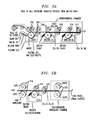
- FIGS. 3A-B are diagrams illustrating a continuous line processing apparatus for fabricating thin film solar cells according to the method of FIG. 1 according to an embodiment of the present invention
- FIGS. 4A-B are diagrams illustrating another continuous line processing apparatus for fabricating thin film solar cells according to the method of FIG. 1 according to an embodiment of the present invention
- FIGS. 5A-B are diagrams illustrating a continuous line processing apparatus for fabricating thin film solar cells according to the method of FIG. 2 according to an embodiment of the present invention
- FIG. 6 is an exemplary drive system that may be employed with any of the continuous-line apparatuses presented herein according to an embodiment of the present invention
- FIG. 7 is a diagram illustrating an alternate embodiment wherein material is deposited onto the rollers using, e.g., a sputtering process, and then transferred to the substrate according to an embodiment of the present invention.
- FIG. 8 is a diagram illustrating another alternate embodiment wherein material is deposited directly onto the substrate using, e.g., a sputtering process, and the rollers are used to apply pressure and/or heat according to an embodiment of the present invention.
- CIGS copper-indium-gallium-sulfur/selenium
- the fabrication of copper-indium-gallium-sulfur/selenium (CIGS) absorbers for thin film solar cell production can be accomplished by successive deposition of elemental layers of the copper (Cu), indium (In), gallium (Ga) and sulfur (S), followed by an anneal in a selenium (Se) environment.
- Cu copper
- In indium
- Ga gallium
- S sulfur
- adhesion problems can occur during the fabrication process as the layers are heated and cooled.
- chalcogenide e.g., CIGS
- CIGS chalcogenide thin film solar cells
- a pressure transfer process for example by way of rollers that apply pressure to both sides of the solar cell workpiece, to control volume expansion and stresses on the CIGS layers that occur during the fabrication process and thereby prevent loss of adhesion between the layers.
- the present techniques are applied to a continuous line chalcogenide (e.g., CIGS) thin film solar cell fabrication process wherein the elemental layers of the CIGS absorber are successively applied to a substrate (e.g., molybdenum (Mo)-coated glass or metal substrate) material that is being continuously fed through the production line.
- CIGS continuous line chalcogenide
- the thin film layers of the absorber are applied at different stages of the continuous line process.
- sets of rollers are employed throughout the fabrication stages to deposit the CIGS layers onto the workpiece and/or heat/cool the workpiece while at the same time applying pressure to both sides of the workpiece. Applying pressure to both sides of the workpiece during the thin film fabrication process serves to passivate the stresses caused by the volume expansion of the layers.
- deposition of the CIGS layers onto the workpiece can be carried out in several different ways.
- an electrodeposition process is used to deposit the CIGS layers using separate electroplating cells.
- the rollers can be used during this electrodeposition process to simultaneously apply pressure to both sides of the workpiece while serving to deposit the CIGS material onto the workpiece (and at some stages of the process heat or cool the workpiece).
- one or more of the CIGS components are deposited onto the workpiece from a molten bath. Again, the rollers can be used during this molten deposition process to simultaneously apply pressure to both sides of the workpiece while serving to deposit the CIGS material onto the workpiece (and at some stages of the process heat or cool the workpiece).
- FIG. 1 An overview of the first exemplary scenario wherein the CIGS materials are deposited onto the workpiece via electrodeposition is provided by way of reference to FIG. 1 . Then an overview of the exemplary scenario wherein one or more of the CIGS materials are deposited from a molten bath is provided by way of reference to FIG. 2 . Exemplary continuous line thin film production apparatuses which may be employed to implement the present techniques will then be shown and described by way of reference to FIGS. 3-5 .
- FIG. 1 is a diagram illustrating an exemplary methodology 100 for fabrication of CIGS thin film solar cells employing electrodeposition. While the present techniques are being described in the context of fabricating a solar cell, in theory the same techniques may be applied in any continuous line thin film fabrication process.
- a substrate material is provided. Suitable substrate materials for solar cell applications include, but are not limited to, glass substrates having a back contact layer formed thereon such as a molybdenum (Mo)-coated glass substrate, and a flexible metal substrate, such as a stainless steel foil substrate.
- the substrate material is fed continuously from a roll, the CIGS absorber material is formed on the substrate material, and the output is spooled onto a second roll. This process is also referred to herein as a roll-to-roll process.
- a Cu layer is deposited onto the substrate material. It is notable that in the case of a Mo-coated glass substrate, in this step the Cu is deposited onto the Mo layer.
- pressure is applied to both sides (i.e., to a top and bottom—to the substrate and Cu layer, respectively) of the workpiece during this Cu deposition step.
- a linear pressure applied to the workpiece during this step is from about 10 N/mm to about 700 N/mm.
- the Cu deposition and simultaneous application of pressure to the workpiece is performed via a set of two rollers that are in contact with opposing sides (i.e., one roller is in contact with the top and one roller is in contact with the bottom) of the workpiece such that as the workpiece is fed through the continuous line fabrication process, the workpiece passes between the set of rollers.
- the rollers are configured to deposit the Cu onto the workpiece from a Cu-containing electrochemical electrolyte solution through which one of the rollers passes.
- the Cu which is electrodeposited onto the roller from the electrolyte solution
- the rollers may be made of a metal such as stainless steel.
- the material in this case Cu
- the rollers are in this step cooled to a temperature of from about ⁇ 5° C. to about 10° C.
- the rollers are configured to simultaneously 1) apply Cu to the workpiece and 2) apply pressure to both sides of the workpiece.
- Pressure is defined herein as a physical force being exerted on a first object (in this case the workpiece) by one or more other objects (in this case the rollers) in contact with the first object.
- a first object in this case the workpiece
- other objects in this case the rollers
- Pressure is applied to the workpiece via the rollers which are in contact with the substrate and the layer currently being deposited.
- pressure from the rollers is exerted simultaneously on the Cu layer and on the substrate.
- pressure from the rollers is exerted simultaneously on the In layer and on the substrate. And so on.
- electrodeposition is only one possible process that may be implemented to deposit the thin film materials onto the substrate.
- the Cu can be deposited onto the rollers using for example a sputtering (or other suitable process) and then transferred from the rollers to the substrate in the manner described above.
- the Cu can be deposited directly onto the substrate and pressure/heat would be applied via the rollers in the manner described above.
- step 106 pressure and heat are applied to the workpiece in step 106 .
- This process of bonding dissimilar metals e.g., the Cu with the metal substrate or with the Mo-coated substrate
- cladding This process of bonding dissimilar metals (e.g., the Cu with the metal substrate or with the Mo-coated substrate) is also referred to herein by the term “cladding.”
- Linear pressure e.g., from about 10 N/mm to about 700 N/mm
- the workpiece may be heated at this step to a temperature of from about 50° C. to about 250° C.
- the heating and simultaneous application of pressure to the workpiece is performed in step 106 via a set of two rollers that are in contact with opposing sides (i.e., one roller is in contact with the top and one roller is in contact with the bottom) of the workpiece such that as the workpiece is fed through the continuous line fabrication process, the workpiece passes between the set of rollers.
- the rollers can be heated to thereby heat the workpiece as the workpiece passes between the rollers.
- the rollers at this stage of the continuous line process are configured to simultaneously 1) heat the workpiece and 2) apply pressure to both sides of the workpiece.
- step 108 an In layer is deposited onto the substrate material on top of the Cu layer.
- pressure is applied to both sides (i.e., to a top and bottom—to the substrate and In layer, respectively) of the workpiece during this In deposition step. Exemplary pressure values that may be employed during this metal deposition step were provided above.
- the In deposition and simultaneous application of pressure to the workpiece is performed via another set of rollers that are in contact with opposing sides (i.e., one roller is in contact with the top and one roller is in contact with the bottom) of the workpiece such that as the workpiece is fed through the continuous line fabrication process, the workpiece passes between the set of rollers.
- the rollers can be configured to deposit the In onto the workpiece from a In-containing electrochemical electrolyte solution through which one of the rollers passes. Namely, the In (which is electrodeposited onto the roller from the electrolyte solution) is transferred from the roller onto the workpiece.
- the transfer of the In from the roller to the workpiece can be facilitated by cooling the roller, see below.
- Exemplary temperature values were provided above regarding cooling the workpiece to facilitate material transfer from the rollers to the workpiece.
- the rollers are configured to simultaneously 1) apply In to the workpiece, and 2) apply pressure to both sides of the workpiece.
- Cladding of the In deposited onto the Cu layer (in step 108 ) is achieved by applying pressure and heat to the workpiece in step 110 . Exemplary temperature and pressure values for this cladding process were provided above.
- electrodeposition is only one exemplary process that may be employed herein for depositing the material onto the substrate.
- another suitable deposition process such as sputtering
- the material onto the rollers may be used to deposit the material onto the rollers, which then apply the material to the substrate in the manner described above.
- the material may be deposited directly onto the substrate with pressure and/or heat being supplied via the rollers as described above.
- the heating and simultaneous application of pressure to the workpiece is performed in step 110 via another set of rollers that are in contact with opposing sides (i.e., one roller is in contact with the top and one roller is in contact with the bottom) of the workpiece such that as the workpiece is fed through the continuous line fabrication process, the workpiece passes between the set of rollers.
- the rollers can be heated to thereby heat the workpiece as the workpiece passes between the rollers.
- the rollers at this stage of the continuous line process are configured to simultaneously 1) heat the workpiece and 2) apply pressure to both sides of the workpiece.
- step 112 a Ga layer is deposited onto the substrate material on top of the In layer.
- pressure is applied to both sides (i.e., to a top and bottom—to the substrate and Ga layer, respectively) of the workpiece during this Ga deposition step. Exemplary pressure values that may be employed during this metal deposition step were provided above.
- the Ga deposition and simultaneous application of pressure to the workpiece is performed via another set of rollers that are in contact with opposing sides (i.e., one roller is in contact with the top and one roller is in contact with the bottom) of the workpiece such that as the workpiece is fed through the continuous line fabrication process, the workpiece passes between the set of rollers.
- the rollers can be configured to deposit the Ga onto the workpiece from a Ga-containing electrochemical electrolyte solution through which one of the rollers passes. Namely, the Ga (which is electrodeposited onto the roller from the electrolyte solution) is transferred from the roller onto the workpiece.
- the transfer of the Ga from the roller to the workpiece can be facilitated by cooling the roller, see below.
- the rollers are in this step are cooled. Exemplary temperature values were provided above regarding cooling the workpiece to facilitate material transfer from the rollers to the workpiece.
- the rollers are configured to simultaneously 1) apply Ga to the workpiece, and 2) apply pressure to both sides of the workpiece.
- Cladding of the Ga deposited onto the In layer (in step 112 ) is achieved by applying pressure and heat to the workpiece in step 114 . Exemplary temperature and pressure values for this cladding process were provided above.
- electrodeposition is only one exemplary process that may be employed herein for depositing the material onto the substrate.
- another suitable deposition process such as sputtering
- the material onto the rollers may be used to deposit the material onto the rollers, which then apply the material to the substrate in the manner described above.
- the material may be deposited directly onto the substrate with pressure and/or heat being supplied via the rollers as described above.
- the heating and simultaneous application of pressure to the workpiece is performed in step 114 via another set of rollers that are in contact with opposing sides (i.e., one roller is in contact with the top and one roller is in contact with the bottom) of the workpiece such that as the workpiece is fed through the continuous line fabrication process, the workpiece passes between the set of rollers.
- the rollers can be heated to thereby heat the workpiece as the workpiece passes between the rollers.
- the rollers at this stage of the continuous line process are configured to simultaneously 1) heat the workpiece and 2) apply pressure to both sides of the workpiece.
- step 116 the workpiece is subjected to an intermediate or soft anneal.
- pressure is applied to the workpiece while the workpiece is heated during step 116 .
- the soft anneal performed in step 116 is optional, uniformity of the final CIGS material will be enhanced by performing this soft/intermediate anneal.
- the workpiece is annealed at a temperature of from about 100° C.
- a final anneal will be performed in an S-containing environment to complete the CIGS absorber.
- the heating and simultaneous application of pressure to the workpiece is performed in step 116 via another set of rollers that are in contact with opposing sides (i.e., one roller is in contact with the top and one roller is in contact with the bottom) of the workpiece such that as the workpiece is fed through the continuous line fabrication process, the workpiece passes between the set of rollers.
- the rollers can be heated to thereby heat the workpiece as the workpiece passes between the rollers.
- the rollers at this stage of the continuous line process are configured to simultaneously 1) heat the workpiece and 2) apply pressure to both sides of the workpiece.
- step 118 a S, Se, or S+Se layer (abbreviated herein as S/Se layer) is deposited onto the substrate material on top of the Ga layer.
- S/Se layer S, Se, or S+Se layer
- pressure is applied to both sides (i.e., to a top and bottom—to the substrate and S/Se layer, respectively) of the workpiece during this S/Se deposition step. Exemplary pressure values that may be employed during this metal deposition step were provided above.
- the S/Se deposition and simultaneous application of pressure to the workpiece is performed via another set of rollers that are in contact with opposing sides (i.e., one roller is in contact with the top and one roller is in contact with the bottom) of the workpiece such that as the workpiece is fed through the continuous line fabrication process, the workpiece passes between the set of rollers.
- the rollers can be configured to deposit the S/Se onto the workpiece from a S/Se-containing electrochemical electrolyte solution through which one of the rollers passes. Namely, the S/Se (which is electrodeposited onto the roller from the electrolyte solution) is transferred from the roller onto the workpiece.
- the transfer of the S/Se from the roller to the workpiece can be facilitated by cooling the roller, see below.
- the rollers are in this step cooled. Exemplary temperature values were provided above regarding cooling the workpiece to facilitate material transfer from the rollers to the workpiece.
- the rollers are configured to simultaneously 1) apply S/Se to the workpiece, and 2) apply pressure to both sides of the workpiece.
- Cladding of the S/Se deposited onto the Ga layer is achieved by applying pressure and heat to the workpiece in step 120 . Exemplary temperature and pressure values for this cladding process were provided above.
- electrodeposition is only one exemplary process that may be employed herein for depositing the material onto the substrate.
- another suitable deposition process such as sputtering
- the material onto the rollers may be used to deposit the material onto the rollers, which then apply the material to the substrate in the manner described above.
- the material may be deposited directly onto the substrate with pressure and/or heat being supplied via the rollers as described above.
- the heating and simultaneous application of pressure to the workpiece is performed in step 120 via another set of rollers that are in contact with opposing sides (i.e., one roller is in contact with the top and one roller is in contact with the bottom) of the workpiece such that as the workpiece is fed through the continuous line fabrication process, the workpiece passes between the set of rollers.
- the rollers can be heated to thereby heat the workpiece as the workpiece passes between the rollers.
- the rollers at this stage of the continuous line process are configured to simultaneously 1) heat the workpiece and 2) apply pressure to both sides of the workpiece.
- step 122 the workpiece is subjected to a final anneal in a S environment.
- pressure is applied to the workpiece while the workpiece is heated during step 122 .
- the workpiece is annealed at a temperature of from about 500° C. to about 600° C., e.g., at a temperature of about 500° C., while a linear pressure of from about 10 N/mm to about 700 N/mm is simultaneously applied to both sides (i.e., to a top and bottom) of the workpiece which, as provided above, also serves to control volume expansion and stresses on the layers of the cell.
- the heating and simultaneous application of pressure to the workpiece is performed in step 122 via another set of rollers that are in contact with opposing sides (i.e., one roller is in contact with the top and one roller is in contact with the bottom) of the workpiece such that as the workpiece is fed through the continuous line fabrication process, the workpiece passes between the set of rollers.
- the rollers can be heated to thereby heat the workpiece as the workpiece passes between the rollers.
- the rollers at this stage of the continuous line process are configured to simultaneously 1) heat the workpiece and 2) apply pressure to both sides of the workpiece.
- the CIGS absorber is now complete. Any further processing of the cell can be carried out using conventional techniques to form a buffer layer, top electrode, etc. to complete the solar cell.
- thin film compositions described above, and elsewhere herein are merely examples intended to illustrate the present techniques, and a variety of other film compositions can be achieved in the manner described herein.
- CZTS Cu 2 ZnSn(Se,S) 4
- FeS 2 Zn 2 P 3
- CdSe CdS
- ZnSe WSe 2
- MoSe 2 MoSe 2
- Bi 2 S 3 Ag 2 S, Cu 2 Zn(Fe,Sn)(Se,S) 4 , CuxS, CdTe, ZnTe, PbSe, PdS, NiS, NiSeS, InP, ZnO, GaAs.
- I-III-IV 2 material is provided below.
- FIG. 2 is a diagram illustrating an exemplary methodology 200 for fabrication of CIGS thin film solar cells wherein one or more of the CIGS materials are deposited from a molten bath. While the present techniques are being described in the context of fabricating a solar cell, in theory the same techniques may be applied in any continuous line thin film fabrication process.
- a substrate material is provided.
- suitable substrate materials for solar cell applications include, but are not limited to, glass substrates having a back contact layer formed thereon such as a Mo-coated glass substrate, and a flexible metal substrate, such as a stainless steel foil substrate.
- the substrate material is fed continuously from a roll, the CIGS absorber material is formed on the substrate material, and the output is spooled onto a second roll. This process is also referred to herein as a roll-to-roll process.
- a Cu layer is deposited onto the substrate material. It is notable that in the case of a Mo-coated glass substrate, in this step the Cu is deposited onto the Mo layer.
- pressure is applied to both sides (i.e., to a top and bottom—to the substrate and Cu layer, respectively) of the workpiece during this Cu deposition step.
- a linear pressure applied to the workpiece during this step is from about 10 N/mm to about 700 N/mm.
- the Cu will be deposited in step 204 by electrodeposition from an electrolyte, whereas the In, Ga and S will be deposited from a molten bath.
- the Cu deposition and simultaneous application of pressure to the workpiece is performed via a set of two rollers that are in contact with opposing sides (i.e., one roller is in contact with the top and one roller is in contact with the bottom) of the workpiece such that as the workpiece is fed through the continuous line fabrication process, the workpiece passes between the set of rollers.
- the rollers can be configured to deposit the Cu onto the workpiece from a Cu-containing electrolyte solution through which one of the rollers passes. Namely, the Cu (which is electrodeposited onto the roller from the electrochemical electrolyte solution) is transferred from the roller onto the workpiece.
- the transfer of the Cu from the roller to the workpiece can be facilitated by cooling the roller. Exemplary temperature values for cooling the rollers to facilitate material transfer from the roller to the workpiece were provided above.
- the rollers are configured to simultaneously 1) apply Cu to the workpiece, and 2) apply pressure to both sides of the workpiece.
- electrodeposition is only one exemplary process that may be employed herein for depositing the material onto the substrate.
- another suitable deposition process such as sputtering
- the material onto the rollers may be used to deposit the material onto the rollers, which then apply the material to the substrate in the manner described above.
- the material may be deposited directly onto the substrate with pressure and/or heat being supplied via the rollers as described above.
- step 206 pressure and heat are applied to the workpiece in step 206 .
- This process of bonding dissimilar metals e.g., the Cu with the metal substrate or with the Mo-coated substrate
- cladding This process of bonding dissimilar metals (e.g., the Cu with the metal substrate or with the Mo-coated substrate) is also referred to herein by the term “cladding.”
- Linear pressure e.g., from about 10 N/mm to about 700 N/mm
- the workpiece may be heated at this step to a temperature of from about 50° C. to about 250° C.
- the heating and simultaneous application of pressure to the workpiece is performed in step 206 via a set of two rollers that are in contact with opposing sides (i.e., one roller is in contact with the top and one roller is in contact with the bottom) of the workpiece such that as the workpiece is fed through the continuous line fabrication process, the workpiece passes between the set of rollers.
- the rollers can be heated to thereby heat the workpiece as the workpiece passes between the rollers.
- the rollers at this stage of the continuous line process are configured to simultaneously 1) heat the workpiece and 2) apply pressure to both sides of the workpiece.
- step 208 an In layer is deposited onto the substrate material on top of the Cu layer.
- pressure is applied to both sides (i.e., to a top and bottom—to the substrate and In layer, respectively) of the workpiece during this In deposition step. Exemplary pressure values that may be employed during this metal deposition step were provided above.
- the In deposition and simultaneous application of pressure to the workpiece is performed via another set of rollers that are in contact with opposing sides (i.e., one roller is in contact with the top and one roller is in contact with the bottom) of the workpiece such that as the workpiece is fed through the continuous line fabrication process, the workpiece passes between the set of rollers.
- the rollers can be configured to deposit the In onto the workpiece from a bath of molten In through which one of the rollers passes. Namely, as the roller passes through the bath, some of the molten In is picked up by the roller and transferred to the workpiece.
- the rollers are configured to simultaneously 1) apply In to the workpiece, 2) apply pressure to both sides of the workpiece.
- step 210 the workpiece is cooled.
- pressure is applied to both sides (i.e., to a top and bottom) of the workpiece during this cooling step.
- the workpiece is cooled in this step to a temperature of from about ⁇ 5° C. to about 10° C. and the linear pressure applied to the workpiece during this step is from about 10 N/mm to about 700 N/mm.
- the cooling and simultaneous application of pressure to the workpiece is performed in step 210 via another set of rollers that are in contact with opposing sides (i.e., one roller is in contact with the top and one roller is in contact with the bottom) of the workpiece such that as the workpiece is fed through the continuous line fabrication process, the workpiece passes between the set of rollers.
- the rollers can be cooled to thereby cool the workpiece as the workpiece passes between the rollers.
- the rollers at this stage of the continuous line process are configured to simultaneously 1) cool the workpiece and 2) apply pressure to both sides of the workpiece.
- step 212 a Ga layer is deposited onto the substrate material on top of the In layer.
- pressure is applied to both sides (i.e., to a top and bottom—to the substrate and Ga layer, respectively) of the workpiece during this Ga deposition step. Exemplary pressure values that may be employed during this metal deposition step were provided above.
- the Ga deposition and simultaneous application of pressure to the workpiece is performed via another set of rollers that are in contact with opposing sides (i.e., one roller is in contact with the top and one roller is in contact with the bottom) of the workpiece such that as the workpiece is fed through the continuous line fabrication process, the workpiece passes between the set of rollers.
- the rollers can be configured to deposit the Ga onto the workpiece from a bath of molten Ga through which one of the rollers passes. Namely, as the roller passes through the bath, some of the molten Ga is picked up by the roller and transferred to the workpiece.
- the rollers are configured to simultaneously 1) apply Ga to the workpiece, 2) apply pressure to both sides of the workpiece.
- step 212 The Ga material deposited in step 212 will still be (at least to some extent) molten after it is transferred to the workpiece.
- step 214 the workpiece is cooled.
- pressure is applied to both sides (i.e., to a top and bottom) of the workpiece during this cooling step. Exemplary temperature and pressure values for this stage of the process were provided above.
- the cooling and simultaneous application of pressure to the workpiece is performed in step 212 via another set of rollers that are in contact with opposing sides (i.e., one roller is in contact with the top and one roller is in contact with the bottom) of the workpiece such that as the workpiece is fed through the continuous line fabrication process, the workpiece passes between the set of rollers.
- the rollers can be cooled to thereby cool the workpiece as the workpiece passes between the rollers.
- the rollers at this stage of the continuous line process are configured to simultaneously 1) cool the workpiece and 2) apply pressure to both sides of the workpiece.
- step 216 the workpiece is subjected to an intermediate or soft anneal.
- pressure is applied to the workpiece while the workpiece is heated during step 216 .
- the soft anneal performed in step 216 is optional, uniformity of the final CIGS material will be enhanced by performing this soft/intermediate anneal.
- the workpiece is annealed at a temperature of from about 100° C.
- a final anneal will be performed in an S-containing environment to complete the CIGS absorber.
- the heating and simultaneous application of pressure to the workpiece is performed in step 216 via another set of rollers that are in contact with opposing sides (i.e., one roller is in contact with the top and one roller is in contact with the bottom) of the workpiece such that as the workpiece is fed through the continuous line fabrication process, the workpiece passes between the set of rollers.
- the rollers can be heated to thereby heat the workpiece as the workpiece passes between the rollers.
- the rollers at this stage of the continuous line process are configured to simultaneously 1) heat the workpiece and 2) apply pressure to both sides of the workpiece.
- step 218 a S/Se layer is deposited onto the substrate material on top of the Ga layer.
- pressure is applied to both sides (i.e., to a top and bottom—to the substrate and S/Se layer, respectively) of the workpiece during this S/Se deposition step. Exemplary pressure values that may be employed during this metal deposition step were provided above.
- the S/Se deposition and simultaneous application of pressure to the workpiece is performed via another set of rollers that are in contact with opposing sides (i.e., one roller is in contact with the top and one roller is in contact with the bottom) of the workpiece such that as the workpiece is fed through the continuous line fabrication process, the workpiece passes between the set of rollers.
- the rollers can be configured to deposit the S/Se onto the workpiece from a bath of molten S/Se through which one of the rollers passes. Namely, as the roller passes through the bath, some of the molten S/Se is picked up by the roller and transferred to the workpiece.
- the rollers are configured to simultaneously 1) apply S/Se to the workpiece, 2) apply pressure to both sides of the workpiece.
- step 218 The S/Se material deposited in step 218 will still be (at least to some extent) molten after it is transferred to the workpiece.
- step 220 the workpiece is cooled.
- pressure is applied to both sides (i.e., to a top and bottom) of the workpiece during this cooling step. Exemplary temperature and pressure values for this stage of the process were provided above.
- the cooling and simultaneous application of pressure to the workpiece is performed in step 220 via another set of rollers that are in contact with opposing sides (i.e., one roller is in contact with the top and one roller is in contact with the bottom) of the workpiece such that as the workpiece is fed through the continuous line fabrication process, the workpiece passes between the set of rollers.
- the rollers can be cooled to thereby cool the workpiece as the workpiece passes between the rollers.
- the rollers at this stage of the continuous line process are configured to simultaneously 1) cool the workpiece and 2) apply pressure to both sides of the workpiece.
- step 222 the workpiece is subjected to a final anneal in a S environment.
- pressure is applied to the workpiece while the workpiece is heated during step 222 .
- the workpiece is annealed at a temperature of from about 500° C. to about 600° C., e.g., at a temperature of about 500° C., while a linear pressure of from about 10 N/mm to about 700 N/mm is simultaneously applied to both sides (i.e., to a top and bottom) of the workpiece which, as provided above, also serves to control volume expansion and stresses on the layers of the cell.
- the heating and simultaneous application of pressure to the workpiece is performed in step 222 via another set of rollers that are in contact with opposing sides (i.e., one roller is in contact with the top and one roller is in contact with the bottom) of the workpiece such that as the workpiece is fed through the continuous line fabrication process, the workpiece passes between the set of rollers.
- the rollers can be heated to thereby heat the workpiece as the workpiece passes between the rollers.
- the rollers at this stage of the continuous line process are configured to simultaneously 1) heat the workpiece and 2) apply pressure to both sides of the workpiece.
- the CIGS absorber is now complete. Any further processing of the cell can be carried out using conventional techniques to form a buffer layer, top electrode, etc. to complete the solar cell.
- the above sequence of processing steps is merely exemplary, and depending on the desired final composition of the thin film solar cell the sequence of steps performed and/or the materials deposited at each of the stages may vary.
- the present process is configurable to a variety of different thin film configurations.
- the present techniques provide means to apply pressure to both sides of the workpiece while simultaneously depositing a thin film material (and potentially also simultaneously heating or cooling the workpiece).
- the exact thin film material being deposited and/or the order in which the materials are deposited, heated/cooled, etc. can be varied yet still remain within the confines of the present techniques.
- the materials may be deposited from an electrochemical solution (via an electrodeposition process) and/or from another chemical solution (e.g., via deposition from a molten bath, sputtering, etc.).
- electrochemical solution as used herein will generally refer to the solutions described herein for use in an electrodeposition process. All other solutions used for depositing the present materials onto the substrate (e.g., molten metal bath) will generally be referred to herein as “chemical solutions.”
- FIGS. 3A-B a continuous line processing apparatus is depicted performing the method described in FIG. 1 , above (i.e., wherein deposition of the various CIGS layers occurs via electrodeposition) on a Mo-coated glass substrate. It is to be understood that FIGS. 3A-B illustrate a single, continuous-line apparatus/process, however, for ease and clarity of depiction, the figure is broken into two parts ( FIG. 3A and FIG. 3B ).
- a Mo-coated glass substrate is fed into the apparatus between a first set of rollers 302 .
- a Cu layer is deposited onto the substrate (i.e., onto the Mo layer of the Mo-coated substrate) while at the same time pressure is applied to both sides (i.e., to a top and bottom) of the workpiece in order to control volume expansion and stresses on the layers of the cell.
- this Cu deposition and simultaneous application of pressure to the workpiece is performed via rollers 302 which as shown in FIG.
- rollers 302 are in contact with opposing sides (i.e., one of rollers 302 is in contact with the top and one of rollers 302 is in contact with the bottom) of the workpiece such that as the workpiece is fed through the continuous line fabrication process, the workpiece passes between rollers 302 .
- the rollers 302 are configured to deposit the Cu onto the workpiece from a Cu-containing electrolyte solution through which one of the rollers 302 passes.
- rollers 302 are made of a metal such as stainless steel. As the bottom roller 302 passes through the Cu-containing electrolyte solution, the Cu is electrodeposited onto the roller from the electrolyte solution.
- the bottom (e.g., metal) roller 302 acts as a cathode for the electrodeposition process.
- the Cu electrodeposited on the bottom roller 302 is then transferred (from the bottom roller 302 ) onto the workpiece.
- the transfer of the Cu from the bottom roller 302 to the workpiece can be facilitated by cooling the rollers 302 . Namely, cooling the rollers will facilitate cladding the Cu to the workpiece, rather than to the (metal) roller itself.
- the rollers 302 are configured to simultaneously 1) apply Cu to the workpiece and 2) apply pressure to both sides of the workpiece.
- the pressure applied to the workpiece by the rollers 302 may be based on the weight of the top roller 302 pressing down on the workpiece against the bottom roller 302 .
- the top roller 302 might have a size (wherein the size of a roller is determined based on its cross-sectional diameter) that equates with a certain weight of the top roller 302 to achieve a desired amount of pressure when the weight of the top roller 302 is applied to the workpiece against the bottom roller 302 . Accordingly the top roller 302 and the bottom roller 302 are not shown to be the same size as one another.
- a (e.g., nitrogen (N 2 )) air knife present in the direction of rotation between the plating cell and the workpiece serves to direct plating solution from the roller 302 back into the Cu plating cell.
- a water jet may also be implemented in the line following the Cu deposition, to clean the workpiece, followed by an air drying step to remove the water.
- step 106 in order to bond the Cu deposited onto the substrate material, pressure and heat are applied to the workpiece in step 106 .
- the pressure serves to control volume expansion and stresses on the layers of the cell.
- this heating and simultaneous application of pressure to the workpiece is performed via rollers 304 that are in contact with opposing sides (i.e., one of the rollers 304 is in contact with the top and one of the rollers 304 is in contact with the bottom) of the workpiece such that as the workpiece is fed through the continuous line fabrication process, the workpiece passes between the rollers 304 .
- the rollers 304 can be heated to thereby heat the workpiece as the workpiece passes between the rollers 304 . Temperature and pressure parameters for this step were provided above.
- the rollers 304 at this stage of the continuous line process are configured to simultaneously 1) heat the workpiece and 2) apply pressure to both sides of the workpiece.
- electrodeposition is only one exemplary process that may be employed herein for depositing the material onto the substrate.
- another suitable deposition process such as sputtering
- the material onto the rollers may be used to deposit the material onto the rollers, which then apply the material to the substrate in the manner described above.
- the material may be deposited directly onto the substrate with pressure and/or heat being supplied via the rollers as described above.
- a In layer is deposited onto the substrate on top of the Cu layer while at the same time pressure is applied to both sides (i.e., to a top and bottom) of the workpiece in order to control volume expansion and stresses on the layers of the cell.
- this In deposition and simultaneous application of pressure to the workpiece is performed via rollers 306 which as shown in FIG. 3A are in contact with opposing sides (i.e., one of rollers 306 is in contact with the top and one of rollers 306 is in contact with the bottom) of the workpiece such that as the workpiece is fed through the continuous line fabrication process, the workpiece passes between rollers 306 .
- the rollers 306 are configured to deposit the In onto the workpiece from an In-containing electrolyte solution through which one of the rollers 306 passes.
- the rollers 302 can be made of a metal such as stainless steel and as the bottom roller 306 passes through the In-containing electrolyte solution, the In is electrodeposited onto the roller from the electrolyte solution (i.e., the bottom roller 306 acts as a cathode for the electrodeposition process). The In electrodeposited on the bottom roller 306 is then transferred (from the bottom roller 306 ) onto the workpiece.
- the transfer of the In from the bottom roller 306 to the workpiece can be facilitated by cooling the rollers 306 —to insure cladding of the In onto the workpiece rather than onto the rollers. Temperature and pressure parameters for this step were provided above.
- the rollers 306 are configured to simultaneously 1) apply In to the workpiece and 2) apply pressure to both sides of the workpiece.
- the pressure applied to the workpiece by the rollers 306 may be based on the weight of the top roller 306 pressing down on the workpiece against the bottom roller 306 . Accordingly, as provided above, the rollers 306 may not be the same size as one another.
- a (e.g., nitrogen (N 2 )) air knife may be present in the direction of rotation between the plating cell and the workpiece to direct plating solution from the rollers 306 back into the In plating cell.
- a water jet may also be implemented in the line following the In deposition, to clean the workpiece, followed by an air drying step to remove the water.
- the air knife, water jet and air drying would be implemented in the same manner as described above in conjunction with the Cu deposition electroplating stage.
- step 110 of FIG. 1 in order to bond the In deposited onto the substrate material, pressure and heat are applied to the workpiece.
- the pressure serves to control volume expansion and stresses on the layers of the cell.
- this heating and simultaneous application of pressure to the workpiece is performed via rollers 308 that are in contact with opposing sides (i.e., one of the rollers 308 is in contact with the top and one of the rollers 308 is in contact with the bottom) of the workpiece such that as the workpiece is fed through the continuous line fabrication process, the workpiece passes between the rollers 308 .
- the rollers 308 can be heated to thereby heat the workpiece as the workpiece passes between the rollers 308 . Temperature and pressure parameters for this step were provided above.
- the rollers 308 at this stage of the continuous line process are configured to simultaneously 1) heat the workpiece and 2) apply pressure to both sides of the workpiece.
- electrodeposition is only one exemplary process that may be employed herein for depositing the material onto the substrate.
- another suitable deposition process such as sputtering
- the material onto the rollers may be used to deposit the material onto the rollers, which then apply the material to the substrate in the manner described above.
- the material may be deposited directly onto the substrate with pressure and/or heat being supplied via the rollers as described above.
- a Ga layer is deposited onto the substrate on top of the In layer while at the same time pressure is applied to both sides (i.e., to a top and bottom) of the workpiece in order to control volume expansion and stresses on the layers of the cell.
- this Ga deposition and simultaneous application of pressure to the workpiece is performed via rollers 310 which as shown in FIG. 3A are in contact with opposing sides (i.e., one of rollers 310 is in contact with the top and one of rollers 310 is in contact with the bottom) of the workpiece such that as the workpiece is fed through the continuous line fabrication process, the workpiece passes between rollers 310 .
- the rollers 310 are configured to deposit the Ga onto the workpiece from a Ga-containing electrolyte solution through which one of the rollers 310 passes.
- the rollers 310 can be made of a metal such as stainless steel and as the bottom roller 310 passes through the Ga-containing electrolyte solution, the Ga is electrodeposited onto the roller from the electrolyte solution (i.e., the bottom roller 310 acts as a cathode for the electrodeposition process). The Ga electrodeposited on the bottom roller 310 is then transferred (from the bottom roller 310 ) onto the workpiece.
- the transfer of the Ga from the bottom roller 310 to the workpiece can be facilitated by cooling the rollers 310 —to insure cladding of the Ga onto the workpiece rather than onto the rollers. Temperature and pressure parameters for this step were provided above.
- the rollers 310 are configured to simultaneously 1) apply Ga to the workpiece and 2) apply pressure to both sides of the workpiece.
- the pressure applied to the workpiece by the rollers 310 may be based on the weight of the top roller 310 pressing down on the workpiece against the bottom roller 310 . Accordingly, as provided above, the rollers 310 may not be the same size as one another.
- a (e.g., nitrogen (N 2 )) air knife may be present in the direction of rotation between the plating cell and the workpiece to direct plating solution from the rollers 310 back into the Ga plating cell.
- a water jet may also be implemented in the line following the Ga deposition, to clean the workpiece, followed by an air drying step to remove the water.
- the air knife, water jet and air drying would be implemented in the same manner as described above in conjunction with the Cu deposition electroplating stage.
- step 114 of FIG. 1 in order to bond the Ga deposited onto the substrate material, pressure and heat are applied to the workpiece.
- the pressure serves to control volume expansion and stresses on the layers of the cell.
- this heating and simultaneous application of pressure to the workpiece is performed via rollers 312 that are in contact with opposing sides (i.e., one of the rollers 312 is in contact with the top and one of the rollers 312 is in contact with the bottom) of the workpiece such that as the workpiece is fed through the continuous line fabrication process, the workpiece passes between the rollers 312 .
- the rollers 312 can be heated to thereby heat the workpiece as the workpiece passes between the rollers 312 . Temperature and pressure parameters for this step were provided above.
- the rollers 312 at this stage of the continuous line process are configured to simultaneously 1) heat the workpiece and 2) apply pressure to both sides of the workpiece.
- an optional soft/intermediate anneal may be performed to enhance the uniformity of the final CIGS material. Temperature and pressure parameters for this step were provided above. As with the heating steps described above, pressure is applied to the workpiece while the workpiece is heated during this soft annealing step. In the exemplary embodiment shown in FIG.
- this heating and simultaneous application of pressure to the workpiece is performed via rollers 314 that are in contact with opposing sides (i.e., one of the rollers 314 is in contact with the top and one of the rollers 314 is in contact with the bottom) of the workpiece such that as the workpiece is fed through the continuous line fabrication process, the workpiece passes between the rollers 314 .
- the rollers 314 can be heated to thereby heat the workpiece as the workpiece passes between the rollers 314 . Temperature and pressure parameters for this step were provided above.
- the rollers 314 at this stage of the continuous line process are configured to simultaneously 1) heat the workpiece and 2) apply pressure to both sides of the workpiece.
- electrodeposition is only one exemplary process that may be employed herein for depositing the material onto the substrate.
- another suitable deposition process such as sputtering
- the material onto the rollers may be used to deposit the material onto the rollers, which then apply the material to the substrate in the manner described above.
- the material may be deposited directly onto the substrate with pressure and/or heat being supplied via the rollers as described above.
- a S and/or Se layer is deposited onto the substrate on top of the Ga layer while at the same time pressure is applied to both sides (i.e., to a top and bottom) of the workpiece in order to control volume expansion and stresses on the layers of the cell.
- this S/Se deposition and simultaneous application of pressure to the workpiece is performed via rollers 316 which as shown in FIG.
- rollers 316 are in contact with opposing sides (i.e., one of rollers 316 is in contact with the top and one of rollers 316 is in contact with the bottom) of the workpiece such that as the workpiece is fed through the continuous line fabrication process, the workpiece passes between rollers 316 . Further, as shown in FIG. 3B , the rollers 316 are configured to deposit the S/Se onto the workpiece from a S/Se-containing electrolyte solution through which one of the rollers 316 passes.
- the rollers 316 can be made of a metal such as stainless steel and as the bottom roller 316 passes through the S/Se-containing electrolyte solution, the S/Se is electrodeposited onto the roller from the electrolyte solution (i.e., the bottom roller 316 acts as a cathode for the electrodeposition process). The S/Se electrodeposited on the bottom roller 316 is then transferred (from the bottom roller 316 ) onto the workpiece. As described above, the transfer of the S/Se from the bottom roller 316 to the workpiece can be facilitated by cooling the rollers 316 —to insure cladding of the S/Se onto the workpiece rather than onto the rollers. Temperature and pressure parameters for this step were provided above.
- the rollers 316 are configured to simultaneously 1) apply S/Se to the workpiece and 2) apply pressure to both sides of the workpiece.
- the pressure applied to the workpiece by the rollers 316 may be based on the weight of the top roller 316 pressing down on the workpiece against the bottom roller 316 . Accordingly, as provided above, the rollers 316 may not be the same size as one another.
- a (e.g., nitrogen (N 2 )) air knife may be present in the direction of rotation between the plating cell and the workpiece to direct plating solution from the rollers 316 back into the S/Se plating cell.
- a water jet may also be implemented in the line following the S/Se deposition, to clean the workpiece, followed by an air drying step to remove the water.
- the air knife, water jet and air drying would be implemented in the same manner as described above in conjunction with the Cu deposition electroplating stage.
- electrodeposition is only one exemplary process that may be employed herein for depositing the material onto the substrate.
- another suitable deposition process such as sputtering
- the material onto the rollers may be used to deposit the material onto the rollers, which then apply the material to the substrate in the manner described above.
- the material may be deposited directly onto the substrate with pressure and/or heat being supplied via the rollers as described above.
- step 120 of FIG. 1 in order to bond the S/Se deposited onto the substrate material, pressure and heat are applied to the workpiece.
- the pressure serves to control volume expansion and stresses on the layers of the cell.
- this heating and simultaneous application of pressure to the workpiece is performed via rollers 318 that are in contact with opposing sides (i.e., one of the rollers 318 is in contact with the top and one of the rollers 318 is in contact with the bottom) of the workpiece such that as the workpiece is fed through the continuous line fabrication process, the workpiece passes between the rollers 318 .
- the rollers 318 can be heated to thereby heat the workpiece as the workpiece passes between the rollers 318 . Temperature and pressure parameters for this step were provided above.
- the rollers 318 at this stage of the continuous line process are configured to simultaneously 1) heat the workpiece and 2) apply pressure to both sides of the workpiece.
- step 122 of FIG. 1 following deposition of the S/Se onto the workpiece a final anneal is performed. Temperature and pressure parameters for this step were provided above. As with the heating steps described above, pressure is applied to the workpiece while the workpiece is heated during this final annealing step. In the exemplary embodiment shown in FIG. 3B , this heating and simultaneous application of pressure to the workpiece is performed via rollers 320 that are in contact with opposing sides (i.e., one of the roller 320 is in contact with the top and one of the roller 320 is in contact with the bottom) of the workpiece such that as the workpiece is fed through the continuous line fabrication process, the workpiece passes between the rollers 320 .
- rollers 320 that are in contact with opposing sides (i.e., one of the roller 320 is in contact with the top and one of the roller 320 is in contact with the bottom) of the workpiece such that as the workpiece is fed through the continuous line fabrication process, the workpiece passes between the rollers 320 .
- the rollers 320 can be heated to thereby heat the workpiece as the workpiece passes between the rollers 320 .
- the rollers 320 at this stage of the continuous line process are configured to simultaneously 1) heat the workpiece and 2) apply pressure to both sides of the workpiece.
- this final anneal is conducted in a S environment.
- the workpiece may be fed (in a continuous line fashion) into a sulfurization annealing chamber.
- the final output is a CIGS panel.
- thin film compositions described above, and elsewhere herein are merely examples intended to illustrate the present techniques, and a variety of other film compositions can be achieved in the manner described herein.
- CZTS Cu 2 ZnSn(Se,S) 4
- FeS 2 Zn 2 P 3
- CdSe CdS
- ZnSe WSe 2
- MoSe 2 MoSe 2
- Bi 2 S 3 Ag 2 S, Cu 2 Zn(Fe,Sn)(Se,S) 4 , CuxS, CdTe, ZnTe, PbSe, PdS, NiS, NiSeS, InP, ZnO, GaAs.
- I-III-IV 2 material is provided below.
- FIGS. 4A-B Another exemplary embodiment implementing the present techniques for continuous-line fabrication of thin film solar cells is now described by way of reference to FIGS. 4A-B .
- a continuous line processing apparatus is depicted performing the method described in FIG. 1 , above (i.e., wherein deposition of the various CIGS layers occurs via electrodeposition) on a metal (e.g., stainless steel (SS) sheet) substrate.
- SS stainless steel
- a stainless steel substrate is fed into the apparatus between a first set of rollers 402 .
- a stainless steel metal substrate is more flexible and can be fed through the continuous line apparatus/process from a roll (as shown in FIG. 4 A—labeled “roll of SS-sheet”).
- additional rollers may be employed in the production line prior to rollers 402 in order to guide the substrate from the roll.
- the particular number and positioning of these ‘guide’ rollers will of course vary depending on the particular set-up at hand, and their use is optional.
- a Cu layer is deposited onto the substrate while at the same time pressure is applied to both sides (i.e., to a top and bottom) of the workpiece in order to control volume expansion and stresses on the layers of the cell.
- this Cu deposition and simultaneous application of pressure to the workpiece is performed via rollers 402 which as shown in FIG. 4A are in contact with opposing sides (i.e., one of rollers 402 is in contact with the top and one of rollers 402 is in contact with the bottom) of the workpiece such that as the workpiece is fed through the continuous line fabrication process, the workpiece passes between rollers 402 . Further, as shown in FIG.
- the rollers 402 are configured to deposit the Cu onto the workpiece from a Cu-containing electrolyte solution through which one of the rollers 402 passes.
- rollers 402 are made of a metal such as stainless steel.
- the Cu is electrodeposited onto the roller from the electrolyte solution.
- the bottom (e.g., metal) roller 402 acts as a cathode for the electrodeposition process.
- the Cu electrodeposited on the bottom roller 402 is then transferred (from the bottom roller 402 ) onto the workpiece.
- the transfer of the Cu from the bottom roller 402 to the workpiece can be facilitated by cooling the rollers 402 .
- cooling the rollers will facilitate cladding the Cu to the workpiece, rather than to the (metal) roller itself.
- the material already deposited and cladded onto the workpiece will aid in removing the material from the roller (similar to when any sort of material is unwound from a roll) and cooling the rollers facilitates removal of the material from the roll.
- the rollers 402 are configured to simultaneously 1) apply Cu to the workpiece and 2) apply pressure to both sides of the workpiece.
- the pressure applied to the workpiece by the rollers 402 may be based on the weight of the top roller 402 pressing down on the workpiece against the bottom roller 402 , and accordingly the top roller 402 and the bottom roller 402 may not be the same size as one another.
- a (e.g., nitrogen (N 2 )) air knife present in the direction of rotation between the plating cell and the workpiece serves to direct plating solution from the rollers 402 back into the Cu plating cell.
- a water jet may also be implemented in the line following the Cu deposition, to clean the workpiece, followed by an air drying step to remove the water.
- step 106 in order to bond the Cu deposited onto the substrate material, pressure and heat are applied to the workpiece in step 106 .
- the pressure serves to control volume expansion and stresses on the layers of the cell.
- this heating and simultaneous application of pressure to the workpiece is performed via rollers 404 that are in contact with opposing sides (i.e., one of the roller 404 is in contact with the top and one of the roller 404 is in contact with the bottom) of the workpiece such that as the workpiece is fed through the continuous line fabrication process, the workpiece passes between the rollers 404 .
- the rollers 404 can be heated to thereby heat the workpiece as the workpiece passes between the rollers 404 . Temperature and pressure parameters for this step were provided above. Thus, in this exemplary embodiment, the rollers 404 at this stage of the continuous line process are configured to simultaneously 1) heat the workpiece and 2) apply pressure to both sides of the workpiece.
- electrodeposition is only one exemplary process that may be employed herein for depositing the material onto the substrate.
- another suitable deposition process such as sputtering
- the material onto the rollers may be used to deposit the material onto the rollers, which then apply the material to the substrate in the manner described above.
- the material may be deposited directly onto the substrate with pressure and/or heat being supplied via the rollers as described above.
- a In layer is deposited onto the substrate on top of the Cu layer while at the same time pressure is applied to both sides (i.e., to a top and bottom) of the workpiece in order to control volume expansion and stresses on the layers of the cell.
- this In deposition and simultaneous application of pressure to the workpiece is performed via rollers 406 which as shown in FIG. 4A are in contact with opposing sides (i.e., one of rollers 406 is in contact with the top and one of rollers 406 is in contact with the bottom) of the workpiece such that as the workpiece is fed through the continuous line fabrication process, the workpiece passes between rollers 406 .
- the rollers 406 are configured to deposit the In onto the workpiece from an In-containing electrolyte solution through which one of the rollers 406 passes.
- the rollers 402 can be made of a metal such as stainless steel and as the bottom roller 406 passes through the In-containing electrolyte solution, the In is electrodeposited onto the roller from the electrolyte solution (i.e., the bottom roller 406 acts as a cathode for the electrodeposition process). The In electrodeposited on the bottom roller 406 is then transferred (from the bottom roller 406 ) onto the workpiece.
- the transfer of the In from the bottom roller 406 to the workpiece can be facilitated by cooling the rollers 406 —to insure cladding of the In onto the workpiece rather than onto the rollers. Temperature and pressure parameters for this step were provided above.
- the rollers 406 are configured to simultaneously 1) apply Cu to the workpiece and 2) apply pressure to both sides of the workpiece.
- the pressure applied to the workpiece by the rollers 406 may be based on the weight of the top roller 406 pressing down on the workpiece against the bottom roller 406 . Accordingly, as provided above, the rollers 406 may not be the same size as one another.
- a (e.g., nitrogen (N 2 )) air knife may be present in the direction of rotation between the plating cell and the workpiece to direct plating solution from the rollers 406 back into the In plating cell.
- a water jet may also be implemented in the line following the In deposition, to clean the workpiece, followed by an air drying step to remove the water.
- the air knife, water jet and air drying would be implemented in the same manner as described above in conjunction with the Cu deposition electroplating stage.
- electrodeposition is only one exemplary process that may be employed herein for depositing the material onto the substrate.
- another suitable deposition process such as sputtering
- the material onto the rollers may be used to deposit the material onto the rollers, which then apply the material to the substrate in the manner described above.
- the material may be deposited directly onto the substrate with pressure and/or heat being supplied via the rollers as described above.
- step 110 of FIG. 1 in order to bond the In deposited onto the substrate material, pressure and heat are applied to the workpiece.
- the pressure serves to control volume expansion and stresses on the layers of the cell.
- this heating and simultaneous application of pressure to the workpiece is performed via rollers 408 that are in contact with opposing sides (i.e., one of the rollers 408 is in contact with the top and one of the rollers 408 is in contact with the bottom) of the workpiece such that as the workpiece is fed through the continuous line fabrication process, the workpiece passes between the rollers 408 .
- the rollers 408 can be heated to thereby heat the workpiece as the workpiece passes between the rollers 408 . Temperature and pressure parameters for this step were provided above.
- the rollers 408 at this stage of the continuous line process are configured to simultaneously 1) heat the workpiece and 2) apply pressure to both sides of the workpiece.
- a Ga layer is deposited onto the substrate on top of the In layer while at the same time pressure is applied to both sides (i.e., to a top and bottom) of the workpiece in order to control volume expansion and stresses on the layers of the cell.
- this Ga deposition and simultaneous application of pressure to the workpiece is performed via rollers 410 which as shown in FIG. 4A are in contact with opposing sides (i.e., one of rollers 410 is in contact with the top and one of rollers 410 is in contact with the bottom) of the workpiece such that as the workpiece is fed through the continuous line fabrication process, the workpiece passes between rollers 410 .
- the rollers 410 are configured to deposit the Ga onto the workpiece from a Ga-containing electrolyte solution through which one of the rollers 410 passes.
- the rollers 410 can be made of a metal such as stainless steel and as the bottom roller 410 passes through the Ga-containing electrolyte solution, the Ga is electrodeposited onto the roller from the electrolyte solution (i.e., the bottom roller 410 acts as a cathode for the electrodeposition process). The Ga electrodeposited on the bottom roller 410 is then transferred (from the bottom roller 410 ) onto the workpiece.
- the transfer of the Ga from the bottom roller 410 to the workpiece can be facilitated by cooling the rollers 410 —to insure cladding of the Ga onto the workpiece rather than onto the rollers. Temperature and pressure parameters for this step were provided above.
- the rollers 410 are configured to simultaneously 1) apply Ga to the workpiece and 2) apply pressure to both sides of the workpiece.
- the pressure applied to the workpiece by the rollers 410 may be based on the weight of the top roller 410 pressing down on the workpiece against the bottom roller 410 . Accordingly, as provided above, the rollers 410 may not be the same size as one another.
- a (e.g., nitrogen (N 2 )) air knife may be present in the direction of rotation between the plating cell and the workpiece to direct plating solution from the rollers 410 back into the Ga plating cell.
- a water jet may also be implemented in the line following the Ga deposition, to clean the workpiece, followed by an air drying step to remove the water.
- the air knife, water jet and air drying would be implemented in the same manner as described above in conjunction with the Cu deposition electroplating stage.
- electrodeposition is only one exemplary process that may be employed herein for depositing the material onto the substrate.
- another suitable deposition process such as sputtering
- the material onto the rollers may be used to deposit the material onto the rollers, which then apply the material to the substrate in the manner described above.
- the material may be deposited directly onto the substrate with pressure and/or heat being supplied via the rollers as described above.
- step 114 of FIG. 1 in order to bond the Ga deposited onto the substrate material, pressure and heat are applied to the workpiece.
- the pressure serves to control volume expansion and stresses on the layers of the cell.
- this heating and simultaneous application of pressure to the workpiece is performed via rollers 412 that are in contact with opposing sides (i.e., one of the rollers 412 is in contact with the top and one of the rollers 412 is in contact with the bottom) of the workpiece such that as the workpiece is fed through the continuous line fabrication process, the workpiece passes between the rollers 412 .
- the rollers 412 can be heated to thereby heat the workpiece as the workpiece passes between the rollers 412 . Temperature and pressure parameters for this step were provided above.
- the rollers 412 at this stage of the continuous line process are configured to simultaneously 1) heat the workpiece and 2) apply pressure to both sides of the workpiece.
- an optional soft/intermediate anneal may be performed to enhance the uniformity of the final CIGS material. Temperature and pressure parameters for this step were provided above. As with the heating steps described above, pressure is applied to the workpiece while the workpiece is heated during this soft annealing step. In the exemplary embodiment shown in FIG.
- this heating and simultaneous application of pressure to the workpiece is performed via rollers 414 that are in contact with opposing sides (i.e., one of the rollers 414 is in contact with the top and one of the rollers 414 is in contact with the bottom) of the workpiece such that as the workpiece is fed through the continuous line fabrication process, the workpiece passes between the rollers 414 .
- the rollers 414 can be heated to thereby heat the workpiece as the workpiece passes between the rollers 414 . Temperature and pressure parameters for this step were provided above.
- the rollers 414 at this stage of the continuous line process are configured to simultaneously 1) heat the workpiece and 2) apply pressure to both sides of the workpiece.
- a S and/or Se layer is deposited onto the substrate on top of the Ga layer while at the same time pressure is applied to both sides (i.e., to a top and bottom) of the workpiece in order to control volume expansion and stresses on the layers of the cell.
- this S/Se deposition and simultaneous application of pressure to the workpiece is performed via rollers 416 which as shown in FIG.
- rollers 416 are in contact with opposing sides (i.e., one of rollers 416 is in contact with the top and one of rollers 416 is in contact with the bottom) of the workpiece such that as the workpiece is fed through the continuous line fabrication process, the workpiece passes between rollers 416 . Further, as shown in FIG. 4B , the rollers 416 are configured to deposit the S/Se onto the workpiece from a S/Se-containing electrolyte solution through which one of the rollers 416 passes.
- the rollers 416 can be made of a metal such as stainless steel and as the bottom roller 416 passes through the S/Se-containing electrolyte solution, the S/Se is electrodeposited onto the roller from the electrolyte solution (i.e., the bottom roller 316 acts as a cathode for the electrodeposition process). The S/Se electrodeposited on the bottom roller 416 is then transferred (from the bottom roller 416 ) onto the workpiece. As described above, the transfer of the S/Se from the bottom roller 416 to the workpiece can be facilitated by cooling the rollers 416 —to insure cladding of the S/Se onto the workpiece rather than onto the rollers. Temperature and pressure parameters for this step were provided above.
- the rollers 416 are configured to simultaneously 1) apply S/Se to the workpiece and 2) apply pressure to both sides of the workpiece.
- the pressure applied to the workpiece by the rollers 416 may be based on the weight of the top roller 416 pressing down on the workpiece against the bottom roller 416 . Accordingly, as provided above, the rollers 416 may not be the same size as one another.
- a (e.g., nitrogen (N 2 )) air knife may be present in the direction of rotation between the plating cell and the workpiece to direct plating solution from the rollers 416 back into the S/Se plating cell.
- a water jet may also be implemented in the line following the S/Se deposition, to clean the workpiece, followed by an air drying step to remove the water.
- the air knife, water jet and air drying would be implemented in the same manner as described above in conjunction with the Cu deposition electroplating stage.
- electrodeposition is only one exemplary process that may be employed herein for depositing the material onto the substrate.
- another suitable deposition process such as sputtering
- the material onto the rollers may be used to deposit the material onto the rollers, which then apply the material to the substrate in the manner described above.
- the material may be deposited directly onto the substrate with pressure and/or heat being supplied via the rollers as described above.
- step 120 of FIG. 1 in order to bond the S/Se deposited onto the substrate material, pressure and heat are applied to the workpiece.
- the pressure serves to control volume expansion and stresses on the layers of the cell.
- this heating and simultaneous application of pressure to the workpiece is performed via rollers 418 that are in contact with opposing sides (i.e., one of the rollers 418 is in contact with the top and one of the rollers 418 is in contact with the bottom) of the workpiece such that as the workpiece is fed through the continuous line fabrication process, the workpiece passes between the rollers 418 .
- the rollers 418 can be heated to thereby heat the workpiece as the workpiece passes between the rollers 418 . Temperature and pressure parameters for this step were provided above.
- the rollers 418 at this stage of the continuous line process are configured to simultaneously 1) heat the workpiece and 2) apply pressure to both sides of the workpiece.
- step 122 of FIG. 1 following deposition of the S/Se onto the workpiece final anneal is performed. Temperature and pressure parameters for this step were provided above. As with the heating steps described above, pressure is applied to the workpiece while the workpiece is heated during this final annealing step. In the exemplary embodiment shown in FIG. 4B , this heating and simultaneous application of pressure to the workpiece is performed via rollers 420 that are in contact with opposing sides (i.e., one of the rollers 420 is in contact with the top and one of the rollers 420 is in contact with the bottom) of the workpiece such that as the workpiece is fed through the continuous line fabrication process, the workpiece passes between the rollers 420 .
- rollers 420 that are in contact with opposing sides (i.e., one of the rollers 420 is in contact with the top and one of the rollers 420 is in contact with the bottom) of the workpiece such that as the workpiece is fed through the continuous line fabrication process, the workpiece passes between the rollers 420 .
- the rollers 420 can be heated to thereby heat the workpiece as the workpiece passes between the rollers 420 .
- the rollers 420 at this stage of the continuous line process are configured to simultaneously 1) heat the workpiece and 2) apply pressure to both sides of the workpiece.
- this final anneal is conducted in a S/Se environment.
- the workpiece may be fed (in a continuous line fashion) into a sulfurization annealing chamber.
- the final output is a CIGS panel.
- FIGS. 5A-B a continuous line processing apparatus is depicted performing the method described in FIG. 2 , above (i.e., wherein deposition of the various CIGS layers occurs via electrodeposition and/or via deposition from a molten bath) on a metal (e.g., stainless steel (SS) sheet) substrate.
- a metal e.g., stainless steel (SS) sheet
- FIGS. 5A-B illustrate a single, continuous-line apparatus/process, however, for ease and clarity of depiction, the figure is broken into two parts ( FIG. 5A and FIG. 5B ).
- FIGS. 5A-B some of the CIGS layers are deposited onto the workpiece from a molten bath rather than via an electroplating cell.
- a stainless steel substrate is fed into the apparatus between a first set of rollers 502 .
- a stainless steel metal substrate is more flexible and can be fed through the continuous line apparatus/process from a roll (as shown in FIG. 5 A—labeled “roll of SS-sheet”).
- additional rollers may be employed in the production line prior to rollers 502 in order to guide the substrate from the roll.
- the particular number and positioning of these ‘guide’ rollers will of course vary depending on the particular set-up at hand, and their use is optional.
- a Cu layer is deposited onto the substrate while at the same time pressure is applied to both sides (i.e., to a top and bottom) of the workpiece in order to control volume expansion and stresses on the layers of the cell.
- this Cu deposition and simultaneous application of pressure to the workpiece is performed via rollers 502 which as shown in FIG. 5A are in contact with opposing sides (i.e., one of rollers 502 is in contact with the top and one of rollers 502 is in contact with the bottom) of the workpiece such that as the workpiece is fed through the continuous line fabrication process, the workpiece passes between rollers 502 . Further, as shown in FIG.
- the rollers 502 are configured to deposit the Cu onto the workpiece from a Cu-containing electrolyte solution through which one of the rollers 502 passes.
- rollers 502 are made of a metal such as stainless steel.
- the Cu is electrodeposited onto the roller from the electrolyte solution.
- the bottom (e.g., metal) roller 502 acts as a cathode for the electrodeposition process.
- the Cu electrodeposited on the bottom roller 502 is then transferred (from the bottom roller 502 ) onto the workpiece.
- the transfer of the Cu from the bottom roller 502 to the workpiece can be facilitated by cooling the rollers 502 .
- cooling the rollers will facilitate cladding the Cu to the workpiece, rather than to the (metal) roller itself.
- the material already deposited and cladded onto the workpiece will aid in removing the material from the roller (similar to when any sort of material is unwound from a roll) and cooling the rollers facilitates removal of the material from the roll.
- Temperature and pressure parameters for this step were provided above.
- the rollers 502 are configured to simultaneously 1) apply Cu to the workpiece and 2) apply pressure to both sides of the workpiece.
- the pressure applied to the workpiece by the rollers 502 may be based on the weight of the top roller 502 pressing down on the workpiece against the bottom roller 502 , and accordingly the top roller 502 and the bottom roller 502 may not be the same size as one another.
- a (e.g., nitrogen (N 2 )) air knife present in the direction of rotation between the plating cell and the workpiece serves to direct plating solution from the rollers 502 back into the Cu plating cell.
- a water jet may also be implemented in the line following the Cu deposition, to clean the workpiece, followed by an air drying step to remove the water.
- electrodeposition is only one exemplary process that may be employed herein for depositing the material onto the substrate.
- another suitable deposition process such as sputtering
- the material onto the rollers may be used to deposit the material onto the rollers, which then apply the material to the substrate in the manner described above.
- the material may be deposited directly onto the substrate with pressure and/or heat being supplied via the rollers as described above.
- step 206 in order to bond the Cu deposited onto the substrate material, pressure and heat are applied to the workpiece in step 206 .
- the pressure serves to control volume expansion and stresses on the layers of the cell.
- this heating and simultaneous application of pressure to the workpiece is performed via rollers 504 that are in contact with opposing sides (i.e., one of the roller 504 is in contact with the top and one of the roller 504 is in contact with the bottom) of the workpiece such that as the workpiece is fed through the continuous line fabrication process, the workpiece passes between the rollers 504 .
- the rollers 504 can be heated to thereby heat the workpiece as the workpiece passes between the rollers 504 . Temperature and pressure parameters for this step were provided above. Thus, in this exemplary embodiment, the rollers 504 at this stage of the continuous line process are configured to simultaneously 1) heat the workpiece and 2) apply pressure to both sides of the workpiece.
- a In layer is deposited onto the substrate on top of the Cu layer while at the same time pressure is applied to both sides (i.e., to a top and bottom) of the workpiece in order to control volume expansion and stresses on the layers of the cell.
- this In deposition and simultaneous application of pressure to the workpiece is performed via rollers 506 which as shown in FIG. 5A are in contact with opposing sides (i.e., one of rollers 506 is in contact with the top and one of rollers 506 is in contact with the bottom) of the workpiece such that as the workpiece is fed through the continuous line fabrication process, the workpiece passes between rollers 506 .
- the rollers 506 are configured to deposit the In onto the workpiece from a bath of molten In through which one of the rollers 506 passes. Namely, as the bottom roller 506 passes through the bath, some of the molten In is picked up by the roller and transferred to the workpiece. As described above, the transfer of the In from the bottom roller 506 to the workpiece can be facilitated by cooling the rollers 506 . Temperature and pressure parameters for this step were provided above. Thus, in this exemplary embodiment, the rollers 506 are configured to simultaneously 1) apply In to the workpiece and 2) apply pressure to both sides of the workpiece.
- the pressure applied to the workpiece by the rollers 506 may be based on the weight of the top roller 506 pressing down on the workpiece against the bottom roller 506 . Accordingly, as provided above, the rollers 506 may not be the same size as one another. As shown in FIG. 5A , a doctor blade may be present in the direction of rotation between the molten In bath and the workpiece to direct molten In from the rollers 506 back into the molten In bath.
- the In material deposited on the workpiece from the molten bath will still be (at least to some extent) molten after it is transferred to the workpiece.
- the workpiece is cooled.
- pressure is applied to both sides (i.e., to a top and bottom) of the workpiece during this cooling step.
- FIG. 1 In the exemplary embodiment shown in FIG.
- this cooling and simultaneous application of pressure to the workpiece is performed via rollers 508 that are in contact with opposing sides (i.e., one of the rollers 508 is in contact with the top and one of the rollers 508 is in contact with the bottom) of the workpiece such that as the workpiece is fed through the continuous line fabrication process, the workpiece passes between the rollers 508 .
- the rollers 508 can be cooled to thereby cool the workpiece as the workpiece passes between the rollers 508 . Temperature and pressure parameters for this step were provided above.
- the rollers 508 at this stage of the continuous line process are configured to simultaneously 1) cool the workpiece and 2) apply pressure to both sides of the workpiece.
- a Ga layer is deposited onto the substrate on top of the In layer while at the same time pressure is applied to both sides (i.e., to a top and bottom) of the workpiece in order to control volume expansion and stresses on the layers of the cell.
- this Ga deposition and simultaneous application of pressure to the workpiece is performed via rollers 510 which as shown in FIG. 5A are in contact with opposing sides (i.e., one of rollers 510 is in contact with the top and one of rollers 510 is in contact with the bottom) of the workpiece such that as the workpiece is fed through the continuous line fabrication process, the workpiece passes between rollers 510 .
- the rollers 510 are configured to deposit the Ga onto the workpiece from a bath of molten Ga through which one of the rollers 510 passes. Namely, as the bottom roller 510 passes through the bath, some of the molten Ga is picked up by the roller and transferred to the workpiece. As described above, the transfer of the Ga from the bottom roller 510 to the workpiece can be facilitated by cooling the rollers 510 —to insure cladding of the Ga onto the workpiece rather than onto the rollers. Temperature and pressure parameters for this step were provided above.
- the rollers 510 are configured to simultaneously 1) apply Ga to the workpiece and 2) apply pressure to both sides of the workpiece.
- the pressure applied to the workpiece by the rollers 510 may be based on the weight of the top roller 510 pressing down on the workpiece against the bottom roller 510 . Accordingly, as provided above, the rollers 510 may not be the same size as one another. As shown in FIG. 5A , a doctor blade may be present in the direction of rotation between the molten Ga bath and the workpiece to direct molten Ga from the rollers 510 back into the molten Ga bath.
- the Ga material deposited on the workpiece from the molten bath will still be (at least to some extent) molten after it is transferred to the workpiece.
- the workpiece is cooled.
- pressure is applied to both sides (i.e., to a top and bottom) of the workpiece during this cooling step.
- FIG. 1 In the exemplary embodiment shown in FIG.
- this cooling and simultaneous application of pressure to the workpiece is performed via rollers 512 that are in contact with opposing sides (i.e., one of the rollers 512 is in contact with the top and one of the rollers 512 is in contact with the bottom) of the workpiece such that as the workpiece is fed through the continuous line fabrication process, the workpiece passes between the rollers 512 .
- the rollers 512 can be cooled to thereby cool the workpiece as the workpiece passes between the rollers 512 . Temperature and pressure parameters for this step were provided above.
- the rollers 512 at this stage of the continuous line process are configured to simultaneously 1) cool the workpiece and 2) apply pressure to both sides of the workpiece.
- an optional soft/intermediate anneal may be performed to enhance the uniformity of the final CIGS material. Temperature and pressure parameters for this step were provided above. As with the heating steps described above, pressure is applied to the workpiece while the workpiece is heated during this soft annealing step. In the exemplary embodiment shown in FIG.
- this heating and simultaneous application of pressure to the workpiece is performed via rollers 514 that are in contact with opposing sides (i.e., one of the rollers 514 is in contact with the top and one of the rollers 514 is in contact with the bottom) of the workpiece such that as the workpiece is fed through the continuous line fabrication process, the workpiece passes between the rollers 514 .
- the rollers 514 can be heated to thereby heat the workpiece as the workpiece passes between the rollers 514 . Temperature and pressure parameters for this step were provided above.
- the rollers 514 at this stage of the continuous line process are configured to simultaneously 1) heat the workpiece and 2) apply pressure to both sides of the workpiece.
- a S and/or Se layer is deposited onto the substrate on top of the Ga layer while at the same time pressure is applied to both sides (i.e., to a top and bottom) of the workpiece in order to control volume expansion and stresses on the layers of the cell.
- this S/Se deposition and simultaneous application of pressure to the workpiece is performed via rollers 516 which as shown in FIG.
- rollers 516 are in contact with opposing sides (i.e., one of rollers 516 is in contact with the top and one of rollers 516 is in contact with the bottom) of the workpiece such that as the workpiece is fed through the continuous line fabrication process, the workpiece passes between rollers 516 .
- the rollers 516 are configured to deposit the S/Se onto the workpiece from a bath of molten S/Se through which one of the rollers 516 passes. Namely, as the bottom roller 516 passes through the bath, some of the molten S/Se is picked up by the roller and transferred to the workpiece.
- the transfer of the S/Se from the bottom roller 516 to the workpiece can be facilitated by cooling the rollers 516 —to insure cladding of the S onto the workpiece rather than onto the rollers. Temperature and pressure parameters for this step were provided above.
- the rollers 516 are configured to simultaneously 1) apply S/Se to the workpiece and 2) apply pressure to both sides of the workpiece.
- the pressure applied to the workpiece by the rollers 516 may be based on the weight of the top roller 516 pressing down on the workpiece against the bottom roller 516 . Accordingly, as provided above, the rollers 516 may not be the same size as one another. As shown in FIG. 5B , a doctor blade may be present in the direction of rotation between the molten S/Se bath and the workpiece to direct molten S/Se from the rollers 516 back into the molten S/Se bath.
- the S/Se material deposited on the workpiece from the molten bath will still be (at least to some extent) molten after it is transferred to the workpiece.
- the workpiece is cooled.
- pressure is applied to both sides (i.e., to a top and bottom) of the workpiece during this cooling step.
- FIG. 1 In the exemplary embodiment shown in FIG.
- this cooling and simultaneous application of pressure to the workpiece is performed via rollers 518 that are in contact with opposing sides (i.e., one of the rollers 518 is in contact with the top and one of the rollers 518 is in contact with the bottom) of the workpiece such that as the workpiece is fed through the continuous line fabrication process, the workpiece passes between the rollers 518 .
- the rollers 518 can be cooled to thereby cool the workpiece as the workpiece passes between the rollers 518 . Temperature and pressure parameters for this step were provided above.
- the rollers 518 at this stage of the continuous line process are configured to simultaneously 1) cool the workpiece and 2) apply pressure to both sides of the workpiece.
- step 222 of FIG. 2 following deposition of the S/Se onto the workpiece final anneal is performed. Temperature and pressure parameters for this step were provided above. As with the heating steps described above, pressure is applied to the workpiece while the workpiece is heated during this final annealing step. In the exemplary embodiment shown in FIG. 5B , this heating and simultaneous application of pressure to the workpiece is performed via rollers 520 that are in contact with opposing sides (i.e., one of the rollers 520 is in contact with the top and one of the rollers 520 is in contact with the bottom) of the workpiece such that as the workpiece is fed through the continuous line fabrication process, the workpiece passes between the rollers 520 .
- rollers 520 that are in contact with opposing sides (i.e., one of the rollers 520 is in contact with the top and one of the rollers 520 is in contact with the bottom) of the workpiece such that as the workpiece is fed through the continuous line fabrication process, the workpiece passes between the rollers 520 .
- the rollers 520 can be heated to thereby heat the workpiece as the workpiece passes between the rollers 520 .
- the rollers 520 at this stage of the continuous line process are configured to simultaneously 1) heat the workpiece and 2) apply pressure to both sides of the workpiece.
- this final anneal is conducted in a S environment.
- the workpiece may be fed (in a continuous line fashion) into a sulfurization annealing chamber.
- the final output is a CIGS panel.
- FIG. 6 is an exemplary drive system for turning the rollers and thereby advancing the workpiece throughout the present continuous-line processing apparatus.
- this drive system may be implemented in any of the apparatus embodiments shown and described above.
- the drive system includes a first roller 602 that is motor-driven.
- the first roller 602 is shown to be turning in a clockwise direction.
- the first roller 602 is in physical contact with one (i.e., roller 604 ) of a set of rollers.
- the roller 602 turns the roller 604 in a counterclockwise direction.
- Both of the sets of rollers 604 and 606 are in physical contact with the workpiece 608 .
- roller 604 In having the roller 604 turn in a counterclockwise direction, the workpiece 608 is advanced (from left to right in the depiction shown). Movement of the workpiece turns the roller 606 in a clockwise direction.
- the sets of rollers in this case roller 604 and roller 606 , also serve to apply pressure to the workpiece, heat/cool the workpiece, and apply film material to the workpiece.
- the function of applying pressure also termed “roll-to-roll pressure—since the pressure is being applied by the two rollers between which the workpiece passes) is now described.
- the rollers are constructed of metal and the pressure applied to the workpiece is supplied based on the weight of the roller on the workpiece.
- the top roller 604 can be configured to have a weight such that the force of roller 604 on the workpiece against roller 606 provides the specified amount of pressure (see above) on the workpiece.
- the size (i.e., diameter) of the top roller can be configured such that the roller has a certain weight and thus applies the desired amount of pressure to the workpiece. This is illustrated in FIG. 6 where the size (i.e., diameter) of roller 604 is less than that of roller 606 .
- deposition of the thin film materials onto the rollers occurs via electrodeposition and/or passage through a molten bath.
- Other deposition processes may however be employed in accordance with the present techniques.
- a deposition process such as spraying, sputtering, and chemical vapor deposition, may be used to deposit the thin film material 706 onto roller 702 , which in turn then transfers the material to a substrate 708 under pressure and/or heating/cooling in the manner described above.
- roller 702 in FIG. 7 generally represents any of the above-described rollers used to apply pressure and/or heat/cool the substrate during thin film deposition.
- material 706 shown being deposited onto the roller 702 in FIG. 7 generally represents any of the materials described herein for use in the thin film solar cell fabrication process according to the present techniques.
- the substrate 708 shown in FIG. 7 generally represents any of the (e.g., Mo-coated glass, metal, etc.) substrates described herein which, depending on the particular stage of production, may have one or more layers of thin films already deposited thereon. It is further noted, that combinations of the teachings provided herein can be implemented, if so desired.
- one or more of the materials can be deposited via the rollers using electrodeposition and/or transfer from a molten bath (as provided above), and one or more other materials can be deposited via the materials being sprayed, etc. on the rollers (as shown in FIG. 7 ).
- one or more of the thin film materials can be deposited directly onto a substrate and the above-described pressure and/or heating/cooling applied via the rollers.
- the rollers 802 and 804 depicted in FIG. 8 generally represent any of the above-described rollers used to apply pressure and/or heat/cool the substrate during thin film deposition.
- the material 806 shown being deposited onto the substrate 808 in FIG. 8 generally represents any of the materials described herein for use in the thin film solar cell fabrication process according to the present techniques.
- any suitable deposition process can be used to deposit the material onto the substrate, including but not limited to spraying, sputtering, and chemical vapor deposition.
- the rollers will be used to apply pressure, heat, etc., then the material should be deposited onto the substrate prior to the substrate passing between the rollers.
- thin film materials described above are examples provided merely to illustrate the present techniques, and a variety of other film compositions can be achieved in the same manner described herein. One would need only to vary the composition of the materials deposited in one or more of the steps and/or the order in which the materials are deposited in order to achieve different solar cell (or any other device) configurations.
- any of the following thin film solar cell compositions CIGS, CZTS (Cu 2 ZnSn(Se,S) 4 ), FeS 2 , Zn 2 P 3 , CdSe, CdS, ZnSe, WSe 2 , MoSe 2 , Bi 2 S 3 , Ag 2 S, Cu 2 Zn(Fe,Sn)(Se,S) 4 , CuxS, CdTe, ZnTe, PbSe, PdS, NiS, NiSeS, InP, ZnO, GaAs.
- a I-III-IV 2 thin film solar cell is produced.
- a I-III-IV 2 material includes at least one from group I element, at least one group III element, and at least one group IV element.
- some I-III-IV 2 materials include, but are not limited to, CuAlGe 2 , CuGaGe 2 , CuAlSn 2 , and CuGaSn 2 .
- the present techniques can be employed to deposit Cu to the substrate, followed by Ga, and finally tin (Sn) all while pressure is applied via the rollers in the manner described above.
Abstract
Description
Claims (18)
Priority Applications (2)
| Application Number | Priority Date | Filing Date | Title |
|---|---|---|---|
| US14/030,019 US9293632B2 (en) | 2013-09-18 | 2013-09-18 | Pressure transfer process for thin film solar cell fabrication |
| US15/018,398 US20160155889A1 (en) | 2013-09-18 | 2016-02-08 | Pressure transfer process for thin film solar cell fabrication |
Applications Claiming Priority (1)
| Application Number | Priority Date | Filing Date | Title |
|---|---|---|---|
| US14/030,019 US9293632B2 (en) | 2013-09-18 | 2013-09-18 | Pressure transfer process for thin film solar cell fabrication |
Related Child Applications (1)
| Application Number | Title | Priority Date | Filing Date |
|---|---|---|---|
| US15/018,398 Division US20160155889A1 (en) | 2013-09-18 | 2016-02-08 | Pressure transfer process for thin film solar cell fabrication |
Publications (2)
| Publication Number | Publication Date |
|---|---|
| US20150079723A1 US20150079723A1 (en) | 2015-03-19 |
| US9293632B2 true US9293632B2 (en) | 2016-03-22 |
Family
ID=52668297
Family Applications (2)
| Application Number | Title | Priority Date | Filing Date |
|---|---|---|---|
| US14/030,019 Expired - Fee Related US9293632B2 (en) | 2013-09-18 | 2013-09-18 | Pressure transfer process for thin film solar cell fabrication |
| US15/018,398 Abandoned US20160155889A1 (en) | 2013-09-18 | 2016-02-08 | Pressure transfer process for thin film solar cell fabrication |
Family Applications After (1)
| Application Number | Title | Priority Date | Filing Date |
|---|---|---|---|
| US15/018,398 Abandoned US20160155889A1 (en) | 2013-09-18 | 2016-02-08 | Pressure transfer process for thin film solar cell fabrication |
Country Status (1)
| Country | Link |
|---|---|
| US (2) | US9293632B2 (en) |
Families Citing this family (2)
| Publication number | Priority date | Publication date | Assignee | Title |
|---|---|---|---|---|
| US9796045B2 (en) * | 2013-12-19 | 2017-10-24 | Sunpower Corporation | Wafer alignment with restricted visual access |
| US10290763B2 (en) | 2016-05-13 | 2019-05-14 | Sunpower Corporation | Roll-to-roll metallization of solar cells |
Citations (7)
| Publication number | Priority date | Publication date | Assignee | Title |
|---|---|---|---|---|
| US20060030149A1 (en) * | 2004-08-06 | 2006-02-09 | Steven Leith | Depositing material on photosensitive material |
| US20070111367A1 (en) * | 2005-10-19 | 2007-05-17 | Basol Bulent M | Method and apparatus for converting precursor layers into photovoltaic absorbers |
| US20090162969A1 (en) * | 2006-10-13 | 2009-06-25 | Basol Bulent M | Method and apparatus to form solar cell absorber layers with planar surface |
| US20090272422A1 (en) * | 2008-04-27 | 2009-11-05 | Delin Li | Solar Cell Design and Methods of Manufacture |
| US20110284134A1 (en) * | 2010-05-20 | 2011-11-24 | Nichols Beth M | Chalcogenide-based materials and methods of making such materials under vacuum using post-chalcogenization techniques |
| US20120175248A1 (en) * | 2011-01-07 | 2012-07-12 | Solopower, Inc. | Roll-to-roll electroplating photovoltaic films |
| US8809674B2 (en) * | 2012-04-25 | 2014-08-19 | Guardian Industries Corp. | Back electrode configuration for electroplated CIGS photovoltaic devices and methods of making same |
Family Cites Families (2)
| Publication number | Priority date | Publication date | Assignee | Title |
|---|---|---|---|---|
| US8242356B2 (en) * | 2007-04-27 | 2012-08-14 | Srini Balasubramanian | Organic photovoltaic cells |
| JP5709032B2 (en) * | 2010-02-12 | 2015-04-30 | 日本電気硝子株式会社 | Manufacturing method of glass film |
-
2013
- 2013-09-18 US US14/030,019 patent/US9293632B2/en not_active Expired - Fee Related
-
2016
- 2016-02-08 US US15/018,398 patent/US20160155889A1/en not_active Abandoned
Patent Citations (7)
| Publication number | Priority date | Publication date | Assignee | Title |
|---|---|---|---|---|
| US20060030149A1 (en) * | 2004-08-06 | 2006-02-09 | Steven Leith | Depositing material on photosensitive material |
| US20070111367A1 (en) * | 2005-10-19 | 2007-05-17 | Basol Bulent M | Method and apparatus for converting precursor layers into photovoltaic absorbers |
| US20090162969A1 (en) * | 2006-10-13 | 2009-06-25 | Basol Bulent M | Method and apparatus to form solar cell absorber layers with planar surface |
| US20090272422A1 (en) * | 2008-04-27 | 2009-11-05 | Delin Li | Solar Cell Design and Methods of Manufacture |
| US20110284134A1 (en) * | 2010-05-20 | 2011-11-24 | Nichols Beth M | Chalcogenide-based materials and methods of making such materials under vacuum using post-chalcogenization techniques |
| US20120175248A1 (en) * | 2011-01-07 | 2012-07-12 | Solopower, Inc. | Roll-to-roll electroplating photovoltaic films |
| US8809674B2 (en) * | 2012-04-25 | 2014-08-19 | Guardian Industries Corp. | Back electrode configuration for electroplated CIGS photovoltaic devices and methods of making same |
Also Published As
| Publication number | Publication date |
|---|---|
| US20150079723A1 (en) | 2015-03-19 |
| US20160155889A1 (en) | 2016-06-02 |
Similar Documents
| Publication | Publication Date | Title |
|---|---|---|
| JP4384237B2 (en) | CIS type thin film solar cell manufacturing method | |
| EP1424735B1 (en) | Method for forming light-absorbing layer | |
| KR20100126717A (en) | Process for making solar cells | |
| EP2381485A2 (en) | Treatment of thin film layers photovoltaic module | |
| KR20110009151A (en) | Manufacturing method of cis thin-film solar cell | |
| WO2008049103A2 (en) | Roll-to-roll electroplating for photovoltaic film manufacturing | |
| CN102237439A (en) | Solar battery manufacturing method | |
| US8021905B1 (en) | Machine and process for sequential multi-sublayer deposition of copper indium gallium diselenide compound semiconductors | |
| US20110117692A1 (en) | Cigs solar cell having thermal expansion buffer layer and method for fabricating the same | |
| US20160155889A1 (en) | Pressure transfer process for thin film solar cell fabrication | |
| US8026124B2 (en) | Method for fabricating copper/indium/gallium/selenium solar cell by wet process under non-vacuum condition | |
| US10032949B2 (en) | Photovoltaic device based on Ag2ZnSn(S,Se)4 absorber | |
| WO2012090506A1 (en) | Film deposition apparatus and method of manufacturing photoelectric conversion element | |
| US10090424B1 (en) | Roll-to-roll solution process method for fabricating CIGS solar cells and system for the same | |
| EP2755242B1 (en) | Method for producing cigs film, and method for manufacturing cigs solar cell using same | |
| US20140076402A1 (en) | Controlled deposition of photovoltaic thin films using interfacial wetting layers | |
| KR102169332B1 (en) | Thin film solar cell comprising an absorbing layer containing an alkali metal and a method for manufacturing the same | |
| US9284639B2 (en) | Method for alkali doping of thin film photovoltaic materials | |
| US20140224312A1 (en) | Deposition of a high surface energy thin film layer for improved adhesion of group i-iii-vi2 solar cells | |
| KR102042656B1 (en) | A solar cell comprising czts thin film with uniform composition and a method of manufacturing the same | |
| TW201507181A (en) | Mrthod of forming chalcopyrite thin film | |
| US20120196131A1 (en) | Assembly for fabricating a structure having a crystalline film, method of making the assembly, crystalline film structure produced by the assembly and crystalline films | |
| KR20140103257A (en) | Thin films and preparation process thereof | |
| JP2014157922A (en) | Method for manufacturing solar cell | |
| Haug | Properties of the Back Contact Interface for Non-Vacuum Deposited Precursor-Based Cu (In, Ga) Se₂ Solar Cells |
Legal Events
| Date | Code | Title | Description |
|---|---|---|---|
| AS | Assignment |
Owner name: INTERNATIONAL BUSINESS MACHINES CORPORATION, NEW Y Free format text: ASSIGNMENT OF ASSIGNORS INTEREST;ASSIGNORS:AHMED, SHAFAAT;DELIGIANNI, HARIKLIA;HUANG, QIANG;AND OTHERS;SIGNING DATES FROM 20130910 TO 20130918;REEL/FRAME:031230/0258 |
|
| AS | Assignment |
Owner name: GLOBALFOUNDRIES U.S. 2 LLC, NEW YORK Free format text: ASSIGNMENT OF ASSIGNORS INTEREST;ASSIGNOR:INTERNATIONAL BUSINESS MACHINES CORPORATION;REEL/FRAME:036550/0001 Effective date: 20150629 |
|
| AS | Assignment |
Owner name: GLOBALFOUNDRIES INC., CAYMAN ISLANDS Free format text: ASSIGNMENT OF ASSIGNORS INTEREST;ASSIGNORS:GLOBALFOUNDRIES U.S. 2 LLC;GLOBALFOUNDRIES U.S. INC.;REEL/FRAME:036779/0001 Effective date: 20150910 |
|
| STCF | Information on status: patent grant |
Free format text: PATENTED CASE |
|
| AS | Assignment |
Owner name: ALSEPHINA INNOVATIONS INC., CANADA Free format text: ASSIGNMENT OF ASSIGNORS INTEREST;ASSIGNOR:GLOBALFOUNDRIES INC.;REEL/FRAME:049669/0749 Effective date: 20181126 |
|
| FEPP | Fee payment procedure |
Free format text: MAINTENANCE FEE REMINDER MAILED (ORIGINAL EVENT CODE: REM.); ENTITY STATUS OF PATENT OWNER: LARGE ENTITY |
|
| LAPS | Lapse for failure to pay maintenance fees |
Free format text: PATENT EXPIRED FOR FAILURE TO PAY MAINTENANCE FEES (ORIGINAL EVENT CODE: EXP.); ENTITY STATUS OF PATENT OWNER: LARGE ENTITY |
|
| STCH | Information on status: patent discontinuation |
Free format text: PATENT EXPIRED DUE TO NONPAYMENT OF MAINTENANCE FEES UNDER 37 CFR 1.362 |
|
| FP | Lapsed due to failure to pay maintenance fee |
Effective date: 20200322 |
|
| AS | Assignment |
Owner name: GLOBALFOUNDRIES INC., CAYMAN ISLANDS Free format text: RELEASE BY SECURED PARTY;ASSIGNOR:WILMINGTON TRUST, NATIONAL ASSOCIATION;REEL/FRAME:054636/0001 Effective date: 20201117 |