US9292090B2 - Haptic feedback device and haptic feedback method - Google Patents
Haptic feedback device and haptic feedback method Download PDFInfo
- Publication number
- US9292090B2 US9292090B2 US14/008,233 US201314008233A US9292090B2 US 9292090 B2 US9292090 B2 US 9292090B2 US 201314008233 A US201314008233 A US 201314008233A US 9292090 B2 US9292090 B2 US 9292090B2
- Authority
- US
- United States
- Prior art keywords
- image
- frequency
- panel
- haptic feedback
- touch
- Prior art date
- Legal status (The legal status is an assumption and is not a legal conclusion. Google has not performed a legal analysis and makes no representation as to the accuracy of the status listed.)
- Active, expires
Links
- 238000000034 method Methods 0.000 title claims description 35
- 230000007274 generation of a signal involved in cell-cell signaling Effects 0.000 claims abstract description 93
- 238000004364 calculation method Methods 0.000 claims abstract description 16
- 238000000605 extraction Methods 0.000 claims description 54
- 230000001419 dependent effect Effects 0.000 claims description 12
- 238000009530 blood pressure measurement Methods 0.000 claims description 10
- 238000004590 computer program Methods 0.000 claims description 5
- 239000000284 extract Substances 0.000 description 16
- 230000008569 process Effects 0.000 description 11
- 238000010586 diagram Methods 0.000 description 8
- 239000000463 material Substances 0.000 description 6
- 230000008859 change Effects 0.000 description 4
- 230000006870 function Effects 0.000 description 4
- 238000012545 processing Methods 0.000 description 4
- 230000016776 visual perception Effects 0.000 description 4
- 230000007423 decrease Effects 0.000 description 3
- 230000003321 amplification Effects 0.000 description 2
- 238000003199 nucleic acid amplification method Methods 0.000 description 2
- NIXOWILDQLNWCW-UHFFFAOYSA-N acrylic acid group Chemical group C(C=C)(=O)O NIXOWILDQLNWCW-UHFFFAOYSA-N 0.000 description 1
- 230000008901 benefit Effects 0.000 description 1
- 230000001413 cellular effect Effects 0.000 description 1
- 239000000470 constituent Substances 0.000 description 1
- 238000007796 conventional method Methods 0.000 description 1
- 238000013461 design Methods 0.000 description 1
- 239000011521 glass Substances 0.000 description 1
- 230000005484 gravity Effects 0.000 description 1
- 239000004973 liquid crystal related substance Substances 0.000 description 1
- 239000002184 metal Substances 0.000 description 1
- 238000012986 modification Methods 0.000 description 1
- 230000004048 modification Effects 0.000 description 1
- 239000004065 semiconductor Substances 0.000 description 1
- 230000001953 sensory effect Effects 0.000 description 1
- 239000007779 soft material Substances 0.000 description 1
- 230000002123 temporal effect Effects 0.000 description 1
- 238000012360 testing method Methods 0.000 description 1
- 230000009466 transformation Effects 0.000 description 1
- 238000013519 translation Methods 0.000 description 1
Images


Classifications
-
- G—PHYSICS
- G06—COMPUTING; CALCULATING OR COUNTING
- G06F—ELECTRIC DIGITAL DATA PROCESSING
- G06F3/00—Input arrangements for transferring data to be processed into a form capable of being handled by the computer; Output arrangements for transferring data from processing unit to output unit, e.g. interface arrangements
- G06F3/01—Input arrangements or combined input and output arrangements for interaction between user and computer
- G06F3/016—Input arrangements with force or tactile feedback as computer generated output to the user
-
- G—PHYSICS
- G06—COMPUTING; CALCULATING OR COUNTING
- G06F—ELECTRIC DIGITAL DATA PROCESSING
- G06F3/00—Input arrangements for transferring data to be processed into a form capable of being handled by the computer; Output arrangements for transferring data from processing unit to output unit, e.g. interface arrangements
- G06F3/01—Input arrangements or combined input and output arrangements for interaction between user and computer
- G06F3/03—Arrangements for converting the position or the displacement of a member into a coded form
- G06F3/041—Digitisers, e.g. for touch screens or touch pads, characterised by the transducing means
-
- G—PHYSICS
- G06—COMPUTING; CALCULATING OR COUNTING
- G06F—ELECTRIC DIGITAL DATA PROCESSING
- G06F2203/00—Indexing scheme relating to G06F3/00 - G06F3/048
- G06F2203/01—Indexing scheme relating to G06F3/01
- G06F2203/014—Force feedback applied to GUI
-
- G—PHYSICS
- G06—COMPUTING; CALCULATING OR COUNTING
- G06F—ELECTRIC DIGITAL DATA PROCESSING
- G06F3/00—Input arrangements for transferring data to be processed into a form capable of being handled by the computer; Output arrangements for transferring data from processing unit to output unit, e.g. interface arrangements
- G06F3/01—Input arrangements or combined input and output arrangements for interaction between user and computer
- G06F3/048—Interaction techniques based on graphical user interfaces [GUI]
- G06F3/0484—Interaction techniques based on graphical user interfaces [GUI] for the control of specific functions or operations, e.g. selecting or manipulating an object, an image or a displayed text element, setting a parameter value or selecting a range
Definitions
- the present invention relates to haptic feedback devices which provide haptic feedback to a user touching a panel.
- Public terminals for example, automated teller machines (ATM) and ticket vending machines
- ATM automated teller machines
- ticket vending machines which include touch panels
- touch panels are conventionally known.
- the number of personal use devices for example, tablet personal computers (PC) and smartphones
- PC personal computers
- Touch panels are input devices which detect touches made on the panel as inputs. Touch panels detect touches made by a user on a graphical user interface (GUI) object (a button, for example) displayed in the display region.
- GUI graphical user interface
- a benefit of user interfaces which use this kind of touch panel is that they have high flexibility with regard to positioning of GUI objects.
- user interfaces using this kind of touch panel provide less sensory feedback upon the press of a button compared to user interfaces using conventional, mechanical buttons. This can cause the user to be uncertain about whether a touch he or she made on the touch panel was correctly detected or not.
- Patent Literature 1 PTL 1
- PTL 1 Patent Literature 1
- the frequency for vibrating the touch panel is varied based on the position touched on the touch panel (touch position).
- the present invention provides a haptic feedback device capable of appropriately providing haptic feedback to a user touching a panel.
- a haptic feedback device which provides haptic feedback to a user touching a panel includes: the panel; a position obtaining unit configured to obtain a first touch position which is a position of a touch made on the panel by the user and a second touch position which is a position of a touch made on the panel by the user after the touch made at the first touch position; a speed calculation unit configured to calculate a speed of a touch starting at the first touch position and ending at the second touch position; a modulation signal generation unit configured to generate a modulation signal having a frequency component at a frequency that increases with the speed; a carrier signal generation unit configured to generate a carrier signal for vibrating the panel; a modulation unit configured to modulate the generated carrier signal using the modulation signal; and an actuator which provides haptic feedback to the user by vibrating the panel in accordance with the modulated carrier signal.
- the haptic feedback device provides appropriate haptic feedback to a user touching a panel.
- FIG. 1 is a block diagram of a haptic feedback device according to the first embodiment.
- FIG. 2 is a planar view of the panel according to the first embodiment.
- FIG. 3 is an example of an image displayed on the panel.
- FIG. 4A is an example of an image displayed on the panel.
- FIG. 4B is an example of a spatial frequency characteristic of an image displayed on the panel.
- FIG. 5 is a graph showing the touch speed monotonically increasing and showing the modulation signal and the haptic signal when the spatial frequency is constant.
- FIG. 6 is a graph showing a constant touch speed and showing the modulation signal and the haptic signal when the spatial frequency is monotonically increasing.
- FIG. 7 is a graph showing the touch speed monotonically increasing and showing the modulation signal and the haptic signal when the spatial frequency decreases after increasing.
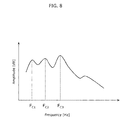
- FIG. 8 is an example of the vibration characteristics of the panel.
- FIG. 9 is a flow chart of the processes performed by the haptic feedback device according to the first embodiment.
- FIG. 10 is a block diagram of a haptic feedback device according to the second embodiment.
- FIG. 11 is a graph showing the corresponding relationship between the spatial frequency and the carrier frequency according to the second embodiment.
- FIG. 12 is a flow chart of the processes performed by the haptic feedback device according to the second embodiment.
- FIG. 13 is a block diagram of a haptic feedback device according to the third embodiment.
- FIG. 14 is a graph showing the corresponding relationship between the degree of elasticity and the carrier frequency according to the third embodiment.
- FIG. 15 is a flow chart of the processes performed by the haptic feedback device according to the third embodiment.
- FIG. 16 is a block diagram of a haptic feedback device according to a variation.
- FIG. 17 is a flow chart of the processes performed by the haptic feedback device according to a variation.
- the panel is vibrated at a frequency appropriate for the characteristics of the panel and the touch position, it is possible to effectively provide stronger haptic feedback to the user.
- simply providing strong haptic feedback when the user touches the panel does not necessarily mean that the haptic feedback is appropriate for the touch made.
- the haptic feedback device provides haptic feedback to a user touching a panel
- the haptic feedback device including: the panel; a position obtaining unit configured to obtain a first touch position which is a position of a touch made on the panel by the user and a second touch position which is a position of a touch made on the panel by the user after the touch made at the first touch position; a speed calculation unit configured to calculate a speed of a touch starting at the first touch position and ending at the second touch position; a modulation signal generation unit configured to generate a modulation signal having a frequency component at a frequency that increases with the speed; a carrier signal generation unit configured to generate a carrier signal for vibrating the panel; a modulation unit configured to modulate the generated carrier signal using the modulation signal; and an actuator which provides haptic feedback to the user by vibrating the panel in accordance with the modulated carrier signal.
- the haptic feedback device may further include: an image display unit configured to display an image on the panel; and an image feature extraction unit configured to extract a feature of the image displayed on the panel, wherein the modulation signal generation unit is configured to generate the modulation signal having a frequency component at a frequency that increases with the speed and is dependent on the feature of the image.
- the image feature extraction unit may be configured to extract, as the feature of the image, a spatial frequency of the image
- the modulation signal generation unit may be configured to generate the modulation signal having a frequency component at a frequency that increases with the speed and the spatial frequency.
- the image feature extraction unit may be configured to extract the feature of the image from a region that is a portion of the image and includes the second touch position.
- the image feature extraction unit may be configured to extract the feature of the image from the region having a size that increases with the speed.
- the image feature extraction unit may be configured to extract the feature of the image each time the image displayed on the panel is updated
- the modulation signal generation unit may be configured to generate the modulation signal each time the feature of the image is extracted.
- the carrier signal generation unit may be configured to generate the carrier signal having a frequency component at a frequency dependent on the feature of the image.
- the image feature extraction unit may be configured to extract, as the feature of the image, a spatial frequency of the image
- the carrier signal generation unit may be configured to generate the carrier signal having a frequency component at a frequency that increases with the spatial frequency
- the haptic feedback device may further include a carrier frequency determination unit configured to determine a resonance frequency to be used for a frequency for the carrier signal from among a plurality of resonance frequencies of the panel, the determined resonance frequency increasing with the spatial frequency, wherein the carrier signal generation unit may be configured to generate the carrier signal having a frequency component at the determined resonance frequency.
- a carrier frequency determination unit configured to determine a resonance frequency to be used for a frequency for the carrier signal from among a plurality of resonance frequencies of the panel, the determined resonance frequency increasing with the spatial frequency
- the carrier signal generation unit may be configured to generate the carrier signal having a frequency component at the determined resonance frequency.
- the carrier signal generation unit may be configured to generate the carrier signal having a frequency component at a resonance frequency of the panel.
- the carrier signal generation unit may be configured to generate the carrier signal having a frequency component at a resonance frequency among a plurality of resonance frequencies of the panel that corresponds to the second touch position.
- the haptic feedback device may further include a hardness obtaining unit configured to obtain a value indicating a hardness of an object included in the image, wherein the carrier signal generation unit may be configured to generate the carrier signal having a frequency component at a frequency that increases with the value indicating the hardness.
- a hardness obtaining unit configured to obtain a value indicating a hardness of an object included in the image
- the carrier signal generation unit may be configured to generate the carrier signal having a frequency component at a frequency that increases with the value indicating the hardness.
- the haptic feedback device may further include a pressure measurement unit configured to measure a pressure of the touch made at the second touch position, wherein the modulation signal generation unit may be configured to generate the modulation signal having a frequency component at a frequency that increases with the measured pressure.
- FIG. 1 is a block diagram of the haptic feedback device 100 according to the first embodiment.
- the haptic feedback device 100 provides haptic feedback to a user touching a touch panel.
- the haptic feedback device 100 includes a panel 101 , a position obtaining unit 102 , an image display unit 103 , an image feature extraction unit 104 , a speed calculation unit 105 , a pressure measurement unit 106 , a modulation signal generation unit 107 , a carrier signal generation unit 108 , a modulation unit 109 , and an actuator 110 .
- FIG. 2 is a planar view of the panel 101 according to the first embodiment.
- the panel 101 receives a touch input from a user. Moreover, the panel 101 conveys vibrations for providing haptic feedback to the user touching the surface of the panel 101 . Furthermore, an image is displayed on the panel 101 by the image display unit 103 .
- the panel 101 is a touch display. More specifically, the panel 101 includes, for example, an electrostatic capacitive or pressure sensitive touch panel and a liquid crystal display or organic EL display device.
- the surface of the panel 101 is, for example, a plate-like member of glass or acrylic.
- the panel 101 has at least one resonance frequency.
- a resonance frequency is a frequency at which the panel 101 naturally vibrates (natural frequency).
- the resonance frequency of the panel 101 depends on, for example, the material and size of the panel 101 .
- the position obtaining unit 102 obtains a position touched on the panel 101 (touch position) by the user when the user touches the panel 101 .
- a position touched on the panel 101 touch position
- two touch positions touched at different times are sometimes differentiated as the first touch position and the second touch position.
- the position obtaining unit 102 obtains a touch position by, for example, electrostatic capacitive method or pressure sensitive method. More specifically, the position obtaining unit 102 obtains, at predetermined time intervals, as the touch position, a central position of a region on the panel 101 touched by the user with his or her finger or a stylus pen (contact region). Moreover, the position obtaining unit 102 may obtain the center of gravity of the load in the contact region as the touch position. It should be noted that, regarding the method of obtaining the touch position, the touch panel is not necessarily limited to an electrostatic capacitive touch panel or resistive touch panel.
- the image display unit 103 is, for example, a graphics processing unit (GPU), and displays an image on the panel 101 .
- the image display unit 103 displays, for example, an image of a stripe pattern like that shown in FIG. 3 on the panel 101 .
- the image that the image display unit 103 displays is not limited to the sort of image shown in FIG. 3
- the image display unit 103 may display a GUI object on the panel 101 .
- the image display unit 103 may display an image captured by a camera on the panel 101 .
- the image display unit 103 may update the condition of the image being displayed based on a touch operation made by the user. For example, the image display unit 103 may update the condition of the image based on temporal changes in the touch position (for example, a pinch-in, pinch-out, or flick motion) obtained by the position obtaining unit 102 .
- the image display unit 103 shrinks the displayed image when a pinch-in motion is detected. Moreover, the image display unit 103 , for example, expands the displayed image when a pinch-out motion is detected. Moreover, when a flick motion is detected, the image display unit 103 , for example, moves the displayed image in the direction of the flick. It should be noted that the method of updating the condition of the image is not limited to these examples.
- the image display unit 103 may update the image being displayed based on information other than the type of touch made by the user. For example, the image display unit 103 may move the image in the direction in which the panel 101 is tilted.
- the image feature extraction unit 104 extracts a feature of the image being displayed on the panel 101 .
- a feature of the image is, for example, texture information or shape information. More specifically, a feature of the image is the spatial frequency or intensity of the image.
- the image feature extraction unit 104 extracts the spatial frequency from the image by performing discrete Fourier transformation (DFT) on the image.
- DFT discrete Fourier transformation
- the image feature extraction unit 104 may obtain, as a feature of the image, the spatial frequency or intensity at a given point on the panel 101 .
- the image feature extraction unit 104 may obtain, as a feature of the image, the spatial frequency or intensity from the surrounding area of the touch position obtained by the position obtaining unit 102 .
- the image feature extraction unit 104 may extract a feature of the image from a region of the image that includes the second touch position.
- the image feature extraction unit 194 may obtain a localized spatial frequency or intensity by extracting image information using an appropriate window function, for example. With this, the image feature extraction unit 104 is capable of extracting a feature dependent on the touch position.
- the image feature extraction unit 104 may extract the feature each time the image displayed on the panel 101 is updated. This enables the image feature extraction unit 104 to extract a feature of the image in synchronization with the changes in condition of the displayed image.
- the image feature amount ⁇ which quantitatively indicates a feature of the image is represented as a function of time, as Equation 1 shows.
- the image feature extraction unit 104 may extract a feature of the image at predetermined time intervals, for example. In this case, the shorter the predetermined time interval is, the faster the image feature extraction unit 104 can keep up with changes in the image being displayed while extracting a feature of the image.
- the speed calculation unit 105 calculates the speed of a touch made by the user (touch speed). More specifically, the speed calculation unit 105 calculates the touch speed by obtaining a time (touch time) at which the first touch position obtained by the position obtaining unit 102 was touched and a time (touch time) at which the second touch position obtained by the position obtaining unit 102 was touched. Even more specifically, the speed calculation unit 105 calculates the touch speed with Equation 2, using the second touch position (x t , y t ) touched at time t and the first touch position (x t-1 , y t-1 ) touched at time (t ⁇ t), for example.
- v x is the touch speed in the left-right direction (horizontal direction)
- v y is the touch speed in the up-down direction (vertical direction).
- the position obtaining unit 102 may, for example, associate corresponding ones of the touch position and touch time, and store this information in memory.
- the speed calculation unit 105 may obtain the first touch position and the corresponding touch time from memory.
- the pressure measurement unit 106 measures a pressure of the touch (touch pressure) made at, the touch position obtained by the position obtaining unit 102 .
- the pressure measurement unit 106 may measure the pressure from the finger contact surface area at the touch position.
- Touch pressure can be obtained using a pressure sensitive touch panel or a load sensor.
- the modulation signal generation unit 107 generates a modulation signal using the feature of the image extracted by the image feature extraction unit 104 .
- a spatial frequency or intensity of the image is used as the feature of the image.
- the modulation signal generation unit 107 for example, generates a modulation signal having a frequency component at a frequency dependent on the feature of the image extracted by the image feature extraction unit 104 .
- the modulation signal generation unit 107 refers to a table which associates the feature of the image and a frequency, or a mathematical formula expressing a relationship between the feature of the image and a frequency, and determines a frequency based on the feature of the image.
- the modulation signal generation unit 107 may generate a modulation signal having a frequency component at a frequency that increases with the spatial frequency of the image. Vibrating the panel in accordance with a carrier signal modulated using this sort of modulation signal allows the haptic feedback device 100 to provide strong haptic feedback to the user when the spatial frequency of the image is high. As such, the haptic feedback device 100 is capable of providing haptic feedback close to the sense of touch the user expects based on the image shown.
- the modulation signal generation unit 107 may generate a modulation signal using the touch speed calculated by the speed calculation unit 105 in addition to the feature of the image extracted by the image feature extraction unit 104 . More specifically, the modulation signal generation unit 107 may, for example, generate a modulation signal having a frequency component at a frequency that increases with the touch speed.
- the image feature extraction unit 104 extracts a region of the image including the current touch position (the second touch position). The image feature extraction unit 104 then obtains a spatial frequency feature such as the one shown in FIG. 4B by performing Fourier transform on the extracted image. The image feature extraction unit 104 obtains the spatial frequency using the spatial frequency feature obtained in this manner.
- the image feature extraction unit 104 extracts, as the image feature amount ⁇ i , a spatial frequency component stronger than a predetermined strength from among the spatial frequency components in the moving direction of the touch.
- the image feature extraction unit 104 extracts spatial frequency ⁇ 1 and ⁇ 2 as the image feature amount.
- the image feature extraction unit 104 may extract, as the image feature amount, the spatial frequency component that is the strongest among the spatial frequency components in the moving direction of the touch.
- the image feature extraction unit 104 may extract a large region when the touch speed is high, and extract a small region when the touch speed is low. In other words, the image feature extraction unit 104 may extract the feature of the image from a region that increases in size with the touch speed. More specifically, the image feature extraction unit 104 may, for example, extract a region whose length is based on the touch speed in the movement direction of the touch from the touch position. With this, the image feature extraction unit 104 is capable of extracting a feature of an image from a region appropriate for the touch speed. Moreover, the image feature extraction unit 104 is capable of resolving the discontinuity of the signal resulting from the extraction, by using an appropriate window function, such as a Hanning window.
- an appropriate window function such as a Hanning window.
- the modulation signal generation unit 107 when the user touches an image by tracing his or her finger across the image, and the image displayed on the panel 101 has a stripe pattern like that shown in FIG. 3 , the modulation signal generation unit 107 generates a modulation signal using Equation 3.
- s m is the modulation signal
- ⁇ i is the strength of the i-th spatial frequency component
- ⁇ i (1/mm) is the i-th spatial frequency
- v (mm/s) is the touch speed.
- the modulation signal generation unit 107 generates, as the modulation signal, a sine wave at a frequency proportionate to the touch speed v and the image feature amount ⁇ 1 .
- (a) is a graph showing the variation in the touch speed overtime
- (b) is a graph showing the variation in the spatial frequency of the image overtime
- (c) is a graph showing the modulation signal
- (d) is a graph showing the haptic signal.
- FIG. 5 shows the touch speed monotonically increasing, and shows the modulation signal and the haptic signal when the spatial frequency is constant.
- the touch speed v (t) monotonically increases from 0 (mm/s) to 10 (mm/s).
- the spatial frequency of the image displayed on the panel 101 is constant at 0.2 (1/mm).
- the modulation signal generation unit 107 generates a modulation signal like the one shown in (c) of FIG. 5 using Equation 3.
- a carrier signal (haptic signal) modulated by the modulation signal shown in (c) in FIG. 5 is shown in (d) in FIG. 5 .
- FIG. 6 shows a constant touch speed, and shows the modulation signal and the haptic signal when the spatial frequency monotonically increases.
- the touch speed v (t) is constant at 20 mm/s.
- the spatial frequency of the image monotonically increases from 0 (1/mm) to 0.3 (1/mm).
- the modulation signal generation unit 107 generates a modulation signal like the one shown in (c) of FIG. 6 using Equation 3.
- a carrier signal (haptic signal) modulated by the modulation signal shown in (c) in FIG. 6 is shown in (d) in FIG. 6 .
- FIG. 7 shows the touch speed monotonously increasing, and shows the modulation signal and the haptic signal when the spatial frequency decreases after increasing.
- the touch speed v (t) monotonically increases from 0 mm/s to 10 mm/s.
- the spatial frequency of the image monotonically increases from 0 (1/mm) to 0.3 (1/mm), and decreases to 0 (1/mm) thereafter.
- the variation in spatial frequency over time shown in (b) in FIG. 7 occurs when, for example, the image displayed on the panel 101 is enlarged after being reduced in size.
- the modulation signal generation unit 107 generates the modulation signal shown in (c) of FIG. 7 using Equation 3. Moreover, in this case, a carrier signal (haptic signal) modulated by the modulation signal shown in (c) in FIG. 6 is shown in (d) in FIG. 7 .
- the frequency of the modulation signal increases.
- the frequency of the modulation signal increases.
- the modulation signal generation unit 107 may generate a modulation signal using the touch pressure measured by the pressure measurement unit 106 in addition to the feature of the image extracted by the image feature extraction unit 104 . More specifically, the modulation signal generation unit 107 may, for example, generate a modulation signal having a frequency component at a frequency that increases with the touch pressure. This allows the haptic feedback device 100 to provide strong haptic feedback when the user touches the panel 101 strongly.
- the modulation signal generation unit 107 may generate a modulation signal using the intensity at the touch position as the feature of the image. More specifically, the modulation signal generation unit 107 generates a modulation signal having an amplitude corresponding to the intensity at the touch position.
- the modulation signal generation unit 107 for example, generates a modulation signal having an amplitude which increases with the intensity of the image at the touch position.
- the modulation signal when, for example, the intensity corresponds to depth-wise direction in the scene (for example, when strong light is coming from in front of the subject), the modulation signal includes a frequency component at a frequency which increases with depth-wise change.
- the haptic feedback device 100 is capable of providing haptic feedback as the user generally would expect from the image.
- D represents the depth of the scene in a position (x, y) on the panel 101 .
- B represents the intensity at the position (x, y) on the panel 101 .
- the modulation signal generation unit 107 generates a modulation signal using, for example, Equation 5.
- the generation method of the modulation signal generated by the modulation signal generation unit 107 is not limited to this example, and may be a method which varies proportionally to depth information.
- the carrier signal generation unit 108 generates a carrier signal for vibrating the panel 101 .
- the carrier signal generation unit 108 generates a carrier signal having a frequency dependent on a vibration characteristic of the panel 101 .
- the carrier signal generation unit 108 generates a carrier signal having a frequency component at a frequency appropriate for vibrating the panel 101 . More specifically, the carrier signal generation unit 108 generates, as the carrier signal s c , a sine wave of the frequency F c , as Equation 6 shows.
- the frequency of the carrier signal may be a resonance frequency of the panel 101 .
- the carrier signal generation unit 108 may generate the carrier signal having a frequency component at a resonance frequency of the panel. This allows the haptic feedback device 100 to efficiently vibrate the panel 101 and provide haptic feedback to the user with low energy.
- FIG. 8 shows an example of the vibration characteristics of the panel 101 .
- the carrier signal generation unit 108 may generate the carrier signal having a frequency component F c3 at a resonance frequency that is the strongest resonance frequency. This allows the haptic feedback device 100 to efficiently vibrate the panel 101 even further, thereby making is possible to further conserve energy.
- the carrier signal generation unit 108 may generate the carrier signal having a frequency component at a resonance frequency that is an average value of the plurality of resonance frequencies appropriate for a plurality of positions on the panel 101 .
- the carrier signal generation unit 108 may generate the carrier signal having a frequency component at a resonance frequency appropriate for the touch position obtained by the position obtaining unit 102 .
- the carrier signal generation unit 108 may generate the carrier signal having a frequency component at a resonance frequency corresponding to the touch position, from among the plurality of resonance frequencies of the panel 101 .
- the modulation unit 109 modulates the carrier signal generated by the carrier signal generation unit 108 using the modulation signal generated by the modulation signal generation unit 107 . More specifically, the modulation unit 109 performs, for example, amplitude modulation (AM). Even more specifically, the modulation unit 109 may perform amplitude modulation on the carrier signal using, for example, Equation 7.
- AM amplitude modulation
- s is the haptic signal
- s m is the modulation signal
- s c is the carrier signal.
- the modulation unit 109 may perform amplitude modulation on the carrier signal using, for example Equation 8.
- the modulation unit 109 generates the haptic signal for driving the actuator 110 by performing amplitude modulation on the carrier signal using the modulation signal.
- the haptic signal generated by the modulation unit 109 is amplified as needed in order to drive the actuator 110 .
- the method of amplification is not limited to any particular method.
- the specific amplification rate may be determined based on the specifications of the actuator 110 .
- the actuator 110 is driven by the carrier signal (haptic signal) modulated by the modulation unit 109 , and vibrates the panel 101 . Vibration of the panel 101 provides haptic feedback to the user. In other words, the actuator 110 provides haptic feedback to the user by vibrating the panel 101 in accordance with the modulated carrier signal.
- haptic signal haptic signal
- the actuator 110 is, for example, applied to the panel 101 .
- the actuator 110 which includes the first actuator 110 A and the second actuator 110 B, is positioned at the periphery of the panel 101 .
- the actuator 110 By being positioned at the periphery of the panel 101 , there is no need to position the actuator 110 in the region in which images are displayed, making it possible to increase the degree of freedom in design.
- the number of actuators is not limited to two. In other words, the actuator 110 may include only one actuator, or may include three or more actuators.
- actuator 110 is not particularly limited to any single type, it is possible to vibrate the panel 101 by using, for example, a piezoelectric element as the actuator 110 .
- a voice coil may be used as the actuator 110 .
- the actuator 110 may include an amplifier for amplifying the haptic signal. When an amplifier is included, the actuator 110 may by driven using an amplified haptic signal. It should be noted that the actuator 110 may be driven using the haptic signal amplified by the carrier signal generation unit 108 . By being driven with an amplified haptic signal, the driving energy of the actuator 110 can be further increased, and the actuator 110 is capable of providing strong haptic feedback to the user.
- FIG. 9 is a flow chart of the processes performed by the haptic feedback device 100 according to the first embodiment.
- the position obtaining unit 102 obtains a position touched on the panel 101 (touch position) by the user at predetermined time intervals.
- the position obtaining unit 102 determines whether haptic feedback is necessary or not based on the touch position obtained in step S 101 .
- the position obtaining unit 102 determines whether haptic feedback is necessary based on whether or not the touch position is in a region of the stripe-textured image.
- the position obtaining unit 102 determines whether haptic feedback is necessary based on whether or not the touch position is in the region the button. If haptic feedback is determined to be necessary, processing proceeds to step S 103 . If haptic feedback is not determined to be necessary, processing returns to step S 101 .
- the criteria for determining whether or not haptic feedback is necessary is not limited to the above example.
- the position obtaining unit 102 may determine that haptic feedback is necessary when the touch position is in a region of the image and the touch position is moving.
- the image display unit 103 updates the condition of the image displayed on the panel 101 based on the touch position obtained by the position obtaining unit 102 .
- the image feature extraction unit 104 extracts a feature of the image being displayed on the panel 101 at predetermined time intervals.
- the modulation signal generation unit 107 generates a modulation signal using the feature of the image extracted in step S 104 .
- the carrier signal generation unit 108 generates a carrier signal for vibrating the panel 101 .
- the modulation unit 109 modulates the carrier signal generated in step S 106 using the modulation signal generated in step S 105 .
- the actuator 110 provides haptic feedback to the user by vibrating the panel 101 in accordance with the carrier signal (haptic signal) modulated in step S 107 .
- haptic feedback device 100 This allows the haptic feedback device 100 to provide haptic feedback dependent on the feature of the age displayed on the panel 101 to the user.
- the haptic feedback device 100 As described above, with the haptic feedback device 100 according to the first embodiment, it is possible to provide haptic feedback based on the image displayed on the panel 101 by vibrating the panel 101 . Moreover, even when the image displayed on the panel 101 changes, the haptic feedback device 100 is capable of providing natural haptic feedback in coordination with visual perception of the user since changes in the image can be reflected in touch as needed.
- the haptic feedback device 100 it is possible to modulate the carrier signal using the modulation signal having a frequency component at a frequency that increases with the speed of the touch, and vibrate the panel in accordance with the modulated carrier signal.
- the haptic feedback device 100 is capable of changing the amplitude of the vibration of the panel more rapidly as the speed of the touch increases, and capable of providing haptic feedback to the user touching the panel that is appropriate for the speed of the touch. This makes it possible for the user to easily confirm by sense of touch that his or her touch has been correctly detected.
- the haptic feedback device differs from that haptic feedback device according to the first embodiment in that the frequency of the carrier signal is changed based on a feature of the image.
- the following description will focus on this point. It should be noted that details regarding structural elements in common with the first embodiment are omitted in the following description.
- FIG. 10 is a block diagram of a haptic feedback device 200 according to the second embodiment.
- the structural elements that are the same as those in FIG. 1 share then same reference numerals, and as such, explanations thereof are omitted.
- the haptic feedback device 200 includes the panel 101 , the position obtaining unit 102 , the image display unit 103 , the image feature extraction unit 104 , the modulation signal generation unit 107 , a carrier signal generation unit 208 , the modulation unit 109 , the actuator 110 , a carrier frequency storage unit 211 , and a carrier frequency determination unit 212 .
- the carrier frequency storage unit 211 stores a carrier signal frequency for each image feature.
- the carrier frequency determination unit 212 obtains, from the carrier frequency storage unit 211 , a frequency corresponding to the feature of the image extracted by the image feature extraction unit 104 .
- the image feature amount ⁇ has one value.
- the image feature amount ⁇ has a value of 0.5 (stripes/mm).
- the carrier frequency determination unit 212 determines a higher frequency for the carrier signal for higher values of the image feature amount ⁇ . Conversely, the carrier frequency determination unit 212 determines a lower frequency for the carrier signal for lower values of the image feature amount ⁇ .
- the frequency of the carrier signal is represented as a function of image feature amount ⁇ , as Equation 9 shows.
- the determination method of the frequency for the carrier signal is not limited to any particular method.
- the carrier frequency determination unit 212 determines a frequency for the carrier signal like FIG. 11 shows. More specifically, the carrier frequency determination unit 212 determines a frequency of F c1 for the carrier signal when 0 ⁇ 1 . Moreover, the carrier frequency determination unit 212 determines a frequency of F c2 for the carrier signal when ⁇ 1 ⁇ 2 . Moreover, the carrier frequency determination unit 212 determines a frequency of F c3 for the carrier signal when ⁇ 2 ⁇ .
- the carrier frequency determination unit 212 determines a higher frequency for the carrier signal for higher values of the spatial frequency. More specifically, the determination of the frequency for the carrier signal by the carrier frequency determination unit 212 is made such that the frequency of the carrier signal increases in a step-like manner when the spatial frequency increases. It should be noted that the threshold values ⁇ 1 and ⁇ 2 for the spatial frequency may be appropriately adjusted based on experience or tests. It should be noted that the determination of the frequency for the carrier signal by the carrier frequency determination unit 212 may be made such that the frequency of the carrier signal increases proportionally or exponentially when the spatial frequency increases.
- the panel 101 does not vibrate uniformly across all frequencies.
- the vibration characteristics of the panel 101 depend on various characteristics (size, thickness, hardness, etc.) of the panel 101 .
- the panel 101 vibrates strongly at: a certain frequency (resonance frequency) due to resonance.
- a resonance frequency as the frequency of the carrier signal makes it possible to effectively vibrate the panel 101 .
- the carrier frequency determination unit 212 determines the frequency for the carrier signal to be a resonance frequency of the panel 101 .
- the carrier frequency determination unit 212 determines a frequency for the carrier signal based on a spatial frequency characteristic of the image like is shown in FIG. 4B . More specifically, the carrier frequency determination unit 212 determines a frequency for the carrier signal using the spatial frequency component having the greatest strength as the spatial frequency of the image.
- the carrier frequency determination unit 212 may determine a frequency for the carrier signal using the spatial frequency component having a strength that is greater than or equal to a predetermined threshold. In this case, when there are a plurality of spatial frequency components having a strength that is greater than or equal to the predetermined threshold, the carrier frequency determination unit 212 may determine each frequency for the carrier signal using the plurality of the spatial frequency components.
- the carrier signal generation unit 208 generates a carrier signal having a frequency determined by the carrier frequency determination unit 212 .
- the carrier signal generation unit 208 generates the carrier signal having a frequency component at a frequency dependent on the feature of the image extracted by the image feature extraction unit 104 .
- the carrier signal generation unit 208 for example, generates the carrier signal having a frequency component at a higher frequency for higher image spatial frequencies.
- the carrier signal generation unit 208 for example, generates the carrier signal having, from among the plurality of resonance frequencies of the panel 101 , a frequency component at a higher resonance frequency for higher spatial frequencies.
- the carrier signal generation unit 208 generates the carrier signal having a frequency component at a plurality of determined frequencies.
- the carrier signal generation unit 208 generates a carrier signal by overlaying each of the sine waves of the plurality of determined frequencies. More specifically, the carrier signal generation unit 208 generates the carrier signal by summing the sine waves of the plurality of frequencies, as Equation 10 shows.
- FIG. 12 is a flow chart showing operations performed by the haptic feedback device 200 according to the second embodiment. It should be noted that detailed description of processes in FIG. 12 that are the same as in FIG. 9 are omitted.
- the position obtaining unit 102 obtains the touch position.
- the position obtaining unit 102 determines whether haptic feedback is necessary or not.
- the image display unit 103 updates the image being displayed as needed.
- the image feature extraction unit 104 extracts a feature of the image being displayed by the image display unit 103 .
- the carrier frequency determination unit 212 determines a frequency for the carrier signal based on the feature of the image extracted by the image feature extraction unit 104 . For example, the carrier frequency determination unit 212 determines a higher frequency for the carrier signal for higher spatial frequencies of the image.
- the haptic signal is generated based on the touch position obtained by the position obtaining unit 102 and the feature of the image extracted by the image feature extraction unit 104 . More specifically, the modulation signal generation unit 107 generates a modulation signal having a frequency component at a frequency corresponding to the feature amount of the image. Moreover, the carrier signal generation unit 208 generates a carrier signal having a frequency determined by the carrier frequency determination unit 212 . The modulation unit 109 then generates the haptic signal by performing amplitude modulation on the carrier signal using the modulation signal.
- the actuator 110 is driven using the haptic signal generated in step S 206 .
- the actuator 110 provides haptic feedback to the user by vibrating the panel 101 in accordance with the haptic signal.
- the haptic feedback device 200 As described above, with the haptic feedback device 200 according to the second embodiment, it is possible to provide haptic feedback based on the image displayed on the panel 101 by vibrating the panel 101 . Furthermore, the haptic feedback device 200 is capable of changing the frequency of the carrier signal based on the feature of the image displayed on the panel 101 . As such, the haptic feedback device 200 is capable of providing soft haptic feedback when the spatial frequency is low, and providing further detailed vibrations when the spatial frequency is high. In other words, the haptic feedback device 200 is capable of generating a carrier signal having a frequency component at a frequency dependent on a feature of the image, and capable of providing haptic feedback to the user touching the panel that is appropriate to the image being displayed on the panel.
- the haptic feedback device 200 is capable of providing natural haptic feedback in coordination with visual perception of the user since changes in the image can be reflected in touch as needed.
- the haptic feedback device 200 may further include the speed calculation unit 105 and the pressure measurement unit 106 .
- the modulation signal generation unit 107 may, for example, generate a modulation signal having a frequency component at a higher frequency for higher touch speeds.
- the modulation signal generation unit 107 may generate a modulation signal having a frequency component at a higher frequency for higher touch pressures.
- the third embodiment is different from the first embodiment in that the frequency of the carrier signal is changed based on the hardness of an object included in the image.
- FIG. 13 is a block diagram of a haptic feedback device 300 according to the third embodiment.
- the structural elements that are the same as those in FIG. 1 share then same reference numerals, and as such, explanations thereof are omitted.
- the haptic feedback device 300 includes the panel 101 , the position obtaining unit 102 , the image display unit 103 , the image feature extraction unit 104 , the modulation signal generation unit 107 , the modulation unit 109 , the actuator 110 , an elasticity storage unit 313 , an elasticity determination unit 314 , a carrier frequency storage unit 311 , a carrier frequency determination unit 312 , and a carrier signal generation unit 308 .
- the elasticity storage unit 313 stores a degree of elasticity (Pa) for each feature of the image.
- the degree of elasticity is one example of a value indicating the hardness of an object included in the image displayed on the panel 101 .
- the degree of elasticity represents materialistic properties of an object included in the image displayed on the panel 101 .
- the elasticity storage unit 313 stores a value indicating the hardness of a material corresponding to a feature of the image, for each feature of the image.
- degree of elasticity is used as a criterion for representing hardness of a material, but this example is not intended to be limiting. In other words, as long as the criterion can express hardness and/or softness of a material, any criterion may be used.
- the elasticity determination unit 314 is an example of the hardness obtaining unit.
- the elasticity determination unit 314 determines a degree of elasticity based on the feature of the image extracted by the image feature extraction unit 104 . In other words, the elasticity determination unit 314 obtains, from the elasticity storage unit 313 , the degree of elasticity corresponding to the extracted feature of the image.
- the carrier frequency storage unit 311 stores a carrier signal frequency for each degree of elasticity. In other words, the carrier frequency storage unit 311 stores a plurality of frequencies each associated with one of a plurality of degrees of elasticity.
- the carrier frequency determination unit 312 determines a frequency for the carrier signal based on the degree of elasticity determined by the elasticity determination unit 314 . More specifically, the carrier frequency determination unit 312 obtains, from the carrier frequency storage unit 311 , a frequency corresponding to the determined degree of elasticity.
- the carrier frequency determination unit 312 determines the frequency for the carrier signal to be a higher frequency for higher degrees of elasticity K, as FIG. 14 shows. It should be noted that similar to the second embodiment, it is preferable that the frequency of the carrier signal is determined from the plurality of resonance frequencies of the panel 101 .
- the carrier signal generation unit 308 generates a carrier signal having a frequency determined by the carrier frequency determination unit 312 .
- the carrier signal generation unit 308 generates the carrier signal having a frequency component at a frequency that increases with the value indicating the hardness of an object included in an image.
- FIG. 15 is a flow chart showing operations performed by the haptic feedback device 300 according to the third embodiment. It should be noted that detailed description of processes in FIG. 15 that are the same as in FIG. 9 are omitted.
- the position obtaining unit 102 obtains the touch position.
- the position obtaining unit 102 determines whether haptic feedback is necessary or not.
- the image display unit 103 updates the image being displayed as needed.
- the image feature extraction unit 104 extracts a feature of the image being displayed by the image display unit 103 .
- the elasticity determination unit 314 obtains a degree of elasticity from the elasticity storage unit 313 based on the feature of the image.
- the carrier frequency determination unit 312 determines a frequency for the carrier signal based on the degree of elasticity. More specifically, the carrier frequency determination unit 312 determines a frequency for the carrier signal such that the frequency of the carrier signal is higher for higher degrees of elasticity. Conversely, the carrier frequency determination unit 312 determines a frequency for the carrier signal such that the frequency of the carrier signal is lower for lower degrees of elasticity.
- the haptic signal is generated based on the feature of the image extracted by the image feature extraction unit 104 , the touch position obtained by the position obtaining unit 102 , and the carrier frequency determined by the carrier frequency determination unit 312 . More specifically, the modulation signal generation unit 107 generates a modulation signal having a frequency component at a frequency corresponding to the feature amount of the image (the spatial frequency). Furthermore, the carrier signal generation unit 308 generates a carrier signal having a frequency determined by the carrier frequency determination unit 312 . The modulation unit 109 then generates the haptic signal by performing amplitude modulation on the carrier signal using the modulation signal.
- the actuator 110 is driven using the haptic signal generated in step S 307 .
- the actuator 110 provides haptic feedback to the user by vibrating the panel 101 in accordance with the haptic signal.
- the haptic feedback device 300 As described above, with the haptic feedback device 300 according to the third embodiment, it is possible to provide haptic feedback based on the image displayed on the panel 101 by vibrating the panel 101 . Furthermore, the haptic feedback device 300 is capable of changing the frequency of the carrier signal based on the materialistic properties of an object included in the image displayed on the panel 101 .
- the haptic feedback device 300 is capable of providing soft, smooth haptic feedback when the included object is soft, and providing further detailed vibrations when the included object is hard. In other words, the haptic feedback device 300 is capable of providing haptic feedback close to the haptic feedback felt when the user touches the actual object, and provide appropriate haptic feedback to the user touching the panel.
- the haptic feedback device 300 is capable of providing natural haptic feedback in coordination with visual perception of the user since changes in the image can be reflected in touch as needed.
- the value indicating the hardness of an object included in the image is obtained from the feature of the image, but the method of obtaining the value indicating hardness is not limited to this example.
- the elasticity determination unit 314 may receive an input of the value indicating hardness from the user.
- the value indicating hardness may be, for example, a value indicating a level of hardness (for example a value from one to five).
- the haptic feedback device 300 may further include the speed calculation unit 105 and the pressure measurement unit 106 .
- the modulation signal generation unit 107 may, for example, generate a modulation signal having a frequency component at a higher frequency for higher touch speeds.
- the modulation signal generation unit 107 may generate a modulation signal having a frequency component at a higher frequency for higher touch pressures.
- haptic feedback device according to one or more aspect was described based on exemplary embodiments, but the present invention is not limited to these exemplary embodiments.
- Various modifications of the exemplary embodiments as well as embodiments resulting from combinations of constituent elements of the different exemplary embodiments that may be conceived by those skilled in the art are intended to be included within the scope of the one or more aspect as long as these do not depart from the essence of the present invention.
- the haptic feedback device is not absolutely required to include the structural elements shown in FIG. 1 , FIG. 10 , or FIG. 15 .
- the haptic feedback device is not absolutely required to include some of the structural elements shown in FIG. 1 , FIG. 10 , or FIG. 15 .
- the haptic feedback device may be configured as FIG. 16 shows.
- FIG. 16 is a block diagram of a haptic feedback device 400 according to a variation.
- FIG. 17 is a flow chart of the processes performed by the haptic feedback device 400 according to the variation. This haptic feedback device 400 does not use a feature of the image when providing haptic feedback to the user touching the panel 101 .
- the haptic feedback device 400 includes the panel 101 , the position obtaining unit 102 , the speed calculation unit 105 , a modulation signal generation unit 407 , the carrier signal generation unit 108 the modulation unit 109 , and the actuator 110 .
- the position obtaining unit 102 obtains a touch position on the panel 101 at predetermined time intervals. In other words, the position obtaining unit 102 obtains a first touch position touched on the panel 101 by the user and a second touch position touch on the panel 101 by the user after the first touch position.
- the speed calculation unit 105 calculates the speed of a touch (touch speed) starting at the first touch position and ending at the second touch position.
- the modulation signal generation unit 407 generates a modulation signal having a frequency component at a higher frequency for higher touch speeds. More specifically, the modulation signal generation unit 407 generates, as the modulation signal s m , a sine wave of a frequency proportional to the touch speed v by a proportional constant k (k>0) as Equation 11 shows, for example.
- the frequency of the modulation signal is not required to be proportional to the touch speed.
- the frequency at the time of the second touch speed may simply be greater than the frequency at the time of the first touch speed (where the second touch speed is greater than the first touch speed).
- the carrier signal generation unit 108 generates a carrier signal for vibrating the panel 101 .
- the carrier signal generation unit 108 generates the carrier signal having a frequency component at a resonance frequency of the panel 101 .
- the carrier signal generation unit 108 may generate the carrier signal having a frequency component at a frequency different than a resonance frequency of the panel 101 .
- the carrier signal generation unit 108 may generate a carrier signal having a frequency component at a frequency haptically perceptible by the user.
- the modulation unit 109 generates the haptic signal by performing amplitude modulation on the carrier signal using the modulation signal. More specifically, the modulation unit 109 generates the haptic signal as Equation 7 or Equation 8 show.
- the actuator 110 provides haptic feedback to the user by vibrating the panel 101 in accordance with the modulated carrier signal (haptic signal).
- the haptic feedback device 400 it is possible to modulate the carrier signal using the modulation signal having a frequency component at a frequency that increases with the speed of the touch, and vibrate the panel in accordance with the modulated carrier signal.
- the haptic feedback device 400 is capable of changing the amplitude of the vibration of the panel more rapidly as the speed of the touch increases, and capable of providing haptic feedback to the user touching the panel that is appropriate for the speed of the touch. This makes it possible for the user to easily confirm by touch that his or her touch has been correctly detected.
- Each of the structural elements in each of the above-described embodiments may be configured in the form of an exclusive hardware product, or may be realized by executing a software program suitable for the structural element.
- Each of the structural elements may be realized by means of a program executing unit, such as a CPU and a processor, reading and executing the software program recorded on a recording medium such as a hard disk or a semiconductor memory.
- the software program for realizing the haptic feedback device according to each of the embodiments is a program described below.
- the program causes the computer to execute a haptic feedback method of providing haptic feedback to a user touching a panel, the haptic feedback method including: obtaining a first touch position which is a position of a touch made on the panel by the user and a second touch position which is a position of a touch made on the panel by the user after the touch made at the first touch position; calculating a speed of a touch starting at the first touch position and ending at the second touch position; generating a modulation signal having a frequency component at a frequency that increases with the speed; generating a carrier signal for vibrating the panel; modulating the generated carrier signal using the modulation signal; and providing haptic feedback to the user by vibrating the panel in accordance with the modulated carrier signal.
- the haptic feedback device is capable of providing haptic feedback to a user touching a panel, and as such is applicable in devices having display panels, such as televisions, digital still cameras, digital movie cameras, personal computers, portable information devices, and cellular phones.
Abstract
Description
- Japanese Unexamined Patent Application Publication (Translation of PCT Application) No. 2011-50295
λi=λi(t) (1)
D(x,y)=1/B(x,y) (4)
S c(t)=sin(2πF c t) (6)
s(t)=s m(t)s c(t) (7)
F c =F c(λ) (9)
s C(t)=Σ sin(2πF c(λi)t) (10)
s m(t)=sin(2πkv(t)t) (11)
- 100, 200, 300, 400 haptic feedback device
- 101 panel
- 102 position obtaining unit
- 103 image display unit
- 104 image feature extraction unit
- 105 speed calculation unit
- 106 pressure measurement unit
- 107, 407 modulation signal generation unit
- 108, 208, 308 carrier signal generation unit
- 109 modulation unit
- 110 actuator
- 110A first actuator
- 110B second actuator
- 211, 311 carrier frequency storage unit
- 212, 312 carrier frequency determination unit
- 313 elasticity storage unit
- 314 elasticity determination unit
Claims (11)
Applications Claiming Priority (3)
| Application Number | Priority Date | Filing Date | Title |
|---|---|---|---|
| JP2012017689 | 2012-01-31 | ||
| JP2012-017689 | 2012-01-31 | ||
| PCT/JP2013/000142 WO2013114792A1 (en) | 2012-01-31 | 2013-01-16 | Tactile-feel presentation device and method for presenting tactile feel |
Publications (2)
| Publication Number | Publication Date |
|---|---|
| US20140062927A1 US20140062927A1 (en) | 2014-03-06 |
| US9292090B2 true US9292090B2 (en) | 2016-03-22 |
Family
ID=48904845
Family Applications (1)
| Application Number | Title | Priority Date | Filing Date |
|---|---|---|---|
| US14/008,233 Active 2033-10-14 US9292090B2 (en) | 2012-01-31 | 2013-01-16 | Haptic feedback device and haptic feedback method |
Country Status (4)
| Country | Link |
|---|---|
| US (1) | US9292090B2 (en) |
| EP (1) | EP2811374B1 (en) |
| JP (1) | JP6044791B2 (en) |
| WO (1) | WO2013114792A1 (en) |
Cited By (2)
| Publication number | Priority date | Publication date | Assignee | Title |
|---|---|---|---|---|
| US10430042B2 (en) * | 2016-09-30 | 2019-10-01 | Sony Interactive Entertainment Inc. | Interaction context-based virtual reality |
| US10444837B2 (en) * | 2013-12-24 | 2019-10-15 | Kyocera Corporation | Tactile sensation providing apparatus |
Families Citing this family (17)
| Publication number | Priority date | Publication date | Assignee | Title |
|---|---|---|---|---|
| US20130318437A1 (en) * | 2012-05-22 | 2013-11-28 | Samsung Electronics Co., Ltd. | Method for providing ui and portable apparatus applying the same |
| US9880623B2 (en) * | 2013-01-24 | 2018-01-30 | Immersion Corporation | Friction modulation for three dimensional relief in a haptic device |
| FR3015383B1 (en) * | 2013-12-19 | 2017-01-13 | Dav | CONTROL DEVICE FOR MOTOR VEHICLE AND CONTROL METHOD |
| JP2016057764A (en) * | 2014-09-08 | 2016-04-21 | 株式会社東海理化電機製作所 | Tactile sense presentation device |
| DE102014224110A1 (en) * | 2014-11-26 | 2016-06-02 | Robert Bosch Gmbh | A method for tactile interaction of a user with an electronic device and electronic device thereto |
| DE102014224102A1 (en) * | 2014-11-26 | 2016-06-02 | Robert Bosch Gmbh | A method for tactile interaction of a user with an electronic device and electronic device thereto |
| US9971406B2 (en) | 2014-12-05 | 2018-05-15 | International Business Machines Corporation | Visually enhanced tactile feedback |
| JP2018513455A (en) | 2015-04-21 | 2018-05-24 | イマージョン コーポレーションImmersion Corporation | Dynamic representation of etching input |
| KR101902248B1 (en) | 2015-08-17 | 2018-09-28 | 엘지전자 주식회사 | Pressure sensitive haptic device |
| DE102015015075A1 (en) * | 2015-11-20 | 2017-05-24 | Audi Ag | Method for operating an input device and input device |
| KR102456953B1 (en) * | 2016-03-11 | 2022-10-21 | 한국전자통신연구원 | apparatus and method for providing image |
| GB2561883A (en) * | 2017-04-27 | 2018-10-31 | Cambridge Touch Tech Ltd | Touchscreen panel haptics |
| US20190073031A1 (en) * | 2017-09-01 | 2019-03-07 | Denso International America, Inc. | Dynamic feedback system and method for providing dynamic feedback |
| JP7087367B2 (en) * | 2017-12-08 | 2022-06-21 | 富士フイルムビジネスイノベーション株式会社 | Information processing equipment, programs and control methods |
| DE102018209963A1 (en) * | 2018-06-20 | 2019-12-24 | Robert Bosch Gmbh | Method for tactile interaction of a user with an electronic device and a computer program product and an electronic device |
| JP7207017B2 (en) * | 2019-03-01 | 2023-01-18 | 株式会社デンソー | input device |
| WO2023119483A1 (en) * | 2021-12-22 | 2023-06-29 | 三菱電機株式会社 | Tactile sensation presentation device, display device, data terminal device, and tactile sensation presentation method |
Citations (39)
| Publication number | Priority date | Publication date | Assignee | Title |
|---|---|---|---|---|
| JPH06297383A (en) | 1993-04-12 | 1994-10-25 | Olympus Optical Co Ltd | Touch sense display device |
| JPH07121350A (en) | 1993-10-22 | 1995-05-12 | Sharp Corp | Writing brush type face generator |
| US5554980A (en) * | 1993-03-12 | 1996-09-10 | Mitsubishi Denki Kabushiki Kaisha | Remote control system |
| JPH1185400A (en) | 1997-09-11 | 1999-03-30 | Sony Corp | Display |
| US6115482A (en) * | 1996-02-13 | 2000-09-05 | Ascent Technology, Inc. | Voice-output reading system with gesture-based navigation |
| US6807861B2 (en) * | 2000-04-28 | 2004-10-26 | School Juridical Person Nihon University | Instrument for noncontact measurement of physical property |
| JP2006012184A (en) | 2005-08-01 | 2006-01-12 | Sony Corp | Display device, information processor and its control method |
| WO2006042309A1 (en) | 2004-10-08 | 2006-04-20 | Immersion Corporation | Haptic feedback for button and scrolling action simulation in touch input devices |
| US20060097996A1 (en) | 2004-11-10 | 2006-05-11 | Alps Electric Co., Ltd. | Input device |
| JP2006139371A (en) | 2004-11-10 | 2006-06-01 | Alps Electric Co Ltd | Input device |
| US20070077024A1 (en) * | 2005-04-15 | 2007-04-05 | Sony Corporation | Input apparatus, input method, input control program, reproduction apparatus, reproduction control method, and reproduction control program |
| US20070291009A1 (en) * | 2006-06-19 | 2007-12-20 | Cypress Semiconductor Corporation | Apparatus and method for detecting a touch-sensor pad gesture |
| JP2008124760A (en) | 2006-11-10 | 2008-05-29 | Hitachi Consulting Co Ltd | Information processor, method of detecting factor influencing health, and program |
| US20080205904A1 (en) * | 2003-06-30 | 2008-08-28 | Nippon Telegraph And Telephone Corporation | Electric Field Sensor Device, Transceiver, Positional Information Obtaining System, and Information Input System |
| US20090085878A1 (en) | 2007-09-28 | 2009-04-02 | Immersion Corporation | Multi-Touch Device Having Dynamic Haptic Effects |
| WO2009051976A1 (en) | 2007-10-17 | 2009-04-23 | Immersion Corporation | Digital envelope modulator for haptic feedback devices |
| US20090135164A1 (en) | 2007-11-26 | 2009-05-28 | Ki Uk Kyung | Pointing apparatus capable of providing haptic feedback, and haptic interaction system and method using the same |
| US20090322695A1 (en) * | 2008-06-25 | 2009-12-31 | Lg Electronics Inc. | Mobile terminal and method of controlling the mobile terminal |
| WO2010016627A1 (en) | 2008-08-08 | 2010-02-11 | Nissha Printing Co., Ltd. | Touch sensitive device |
| US20100073304A1 (en) | 2008-09-24 | 2010-03-25 | Immersion Corporation, A Delaware Corporation | Multiple Actuation Handheld Device |
| US20100283745A1 (en) * | 2007-05-23 | 2010-11-11 | Commissariat A L'energie Atomique | Method for locating a touch on a surface and device for implementing the method |
| US20110096092A1 (en) * | 2009-10-22 | 2011-04-28 | Case Western Reserve University | Non-cartesian caipirinha |
| JP2011129047A (en) | 2009-12-21 | 2011-06-30 | Kyocera Corp | Tactile sense presentation device |
| JP2011159110A (en) | 2010-02-01 | 2011-08-18 | Tohoku Univ | Force presentation method and apparatus |
| US20110216032A1 (en) * | 2010-03-05 | 2011-09-08 | Wacom Co., Ltd. | Position detection apparatus |
| US20110218737A1 (en) * | 2010-03-05 | 2011-09-08 | Vialogy Llc | Active Noise Injection Computations for Improved Predictability in Oil and Gas Reservoir Discovery and Characterization |
| US20120023426A1 (en) * | 2010-07-22 | 2012-01-26 | Mediatek Inc. | Apparatuses and Methods for Position Adjustment of Widget Presentations |
| US20120036435A1 (en) * | 2010-08-04 | 2012-02-09 | Mediatek Inc. | Apparatuses and Methods for Rearranging Menu Items |
| US20120200520A1 (en) * | 2009-10-02 | 2012-08-09 | New Transducers Limited | Touch Sensitive Device |
| US20120235942A1 (en) * | 2000-01-19 | 2012-09-20 | Immersion Corporation | Haptic interface for touch screen embodiments |
| US20130044049A1 (en) * | 2009-03-10 | 2013-02-21 | Bayer Materialscience Ag | Electroactive polymer transducers for tactile feedback devices |
| US20130215033A1 (en) * | 2000-12-22 | 2013-08-22 | Logitech Europe S.A. | Pointing device with solid-state roller |
| US8525799B1 (en) * | 2007-04-24 | 2013-09-03 | Cypress Semiconductor Conductor | Detecting multiple simultaneous touches on a touch-sensor device |
| US20130285910A1 (en) * | 2012-01-17 | 2013-10-31 | Panasonic Corporation | Electronic device |
| US20140071071A1 (en) * | 2012-01-30 | 2014-03-13 | Panasonic Corporation | Haptic feedback device and haptic feedback method |
| US8749494B1 (en) * | 2008-06-24 | 2014-06-10 | Sprint Communications Company L.P. | Touch screen offset pointer |
| US20140210796A1 (en) * | 2011-07-28 | 2014-07-31 | Commissariat A L'energie Atomique Et Aux Ene Alt | System and method for detecting and locating a disturbance in a medium |
| US20150241540A1 (en) * | 2012-09-11 | 2015-08-27 | Koninklijke Philips N.V. | Measurement of magnetic resonance rheology transducer vibrations using navigators |
| US20150301338A1 (en) * | 2011-12-06 | 2015-10-22 | e-Vision Smart Optics ,Inc. | Systems, Devices, and/or Methods for Providing Images |
-
2013
- 2013-01-16 WO PCT/JP2013/000142 patent/WO2013114792A1/en active Application Filing
- 2013-01-16 EP EP13743679.6A patent/EP2811374B1/en active Active
- 2013-01-16 JP JP2013556231A patent/JP6044791B2/en active Active
- 2013-01-16 US US14/008,233 patent/US9292090B2/en active Active
Patent Citations (52)
| Publication number | Priority date | Publication date | Assignee | Title |
|---|---|---|---|---|
| US5554980A (en) * | 1993-03-12 | 1996-09-10 | Mitsubishi Denki Kabushiki Kaisha | Remote control system |
| JPH06297383A (en) | 1993-04-12 | 1994-10-25 | Olympus Optical Co Ltd | Touch sense display device |
| JPH07121350A (en) | 1993-10-22 | 1995-05-12 | Sharp Corp | Writing brush type face generator |
| US6115482A (en) * | 1996-02-13 | 2000-09-05 | Ascent Technology, Inc. | Voice-output reading system with gesture-based navigation |
| JPH1185400A (en) | 1997-09-11 | 1999-03-30 | Sony Corp | Display |
| US20120235942A1 (en) * | 2000-01-19 | 2012-09-20 | Immersion Corporation | Haptic interface for touch screen embodiments |
| US6807861B2 (en) * | 2000-04-28 | 2004-10-26 | School Juridical Person Nihon University | Instrument for noncontact measurement of physical property |
| US20130215033A1 (en) * | 2000-12-22 | 2013-08-22 | Logitech Europe S.A. | Pointing device with solid-state roller |
| US20080205904A1 (en) * | 2003-06-30 | 2008-08-28 | Nippon Telegraph And Telephone Corporation | Electric Field Sensor Device, Transceiver, Positional Information Obtaining System, and Information Input System |
| US20120299857A1 (en) | 2004-10-08 | 2012-11-29 | Immersion Corporation | Haptic Feedback for Button and Scrolling Action Simulation in Touch Input Devices |
| US20060119586A1 (en) | 2004-10-08 | 2006-06-08 | Immersion Corporation, A Delaware Corporation | Haptic feedback for button and scrolling action simulation in touch input devices |
| US20060109256A1 (en) * | 2004-10-08 | 2006-05-25 | Immersion Corporation, A Delaware Corporation | Haptic feedback for button and scrolling action simulation in touch input devices |
| US8232969B2 (en) | 2004-10-08 | 2012-07-31 | Immersion Corporation | Haptic feedback for button and scrolling action simulation in touch input devices |
| JP2008516348A (en) | 2004-10-08 | 2008-05-15 | イマージョン コーポレーション | Haptic feedback for simulating buttons and scrolling motion on touch input devices |
| WO2006042309A1 (en) | 2004-10-08 | 2006-04-20 | Immersion Corporation | Haptic feedback for button and scrolling action simulation in touch input devices |
| US8264465B2 (en) | 2004-10-08 | 2012-09-11 | Immersion Corporation | Haptic feedback for button and scrolling action simulation in touch input devices |
| JP2006139371A (en) | 2004-11-10 | 2006-06-01 | Alps Electric Co Ltd | Input device |
| US20060097996A1 (en) | 2004-11-10 | 2006-05-11 | Alps Electric Co., Ltd. | Input device |
| US20070077024A1 (en) * | 2005-04-15 | 2007-04-05 | Sony Corporation | Input apparatus, input method, input control program, reproduction apparatus, reproduction control method, and reproduction control program |
| JP2006012184A (en) | 2005-08-01 | 2006-01-12 | Sony Corp | Display device, information processor and its control method |
| US20070291009A1 (en) * | 2006-06-19 | 2007-12-20 | Cypress Semiconductor Corporation | Apparatus and method for detecting a touch-sensor pad gesture |
| US20110002512A1 (en) | 2006-11-10 | 2011-01-06 | Sayuri Uehara | Information processor, method of detecting factor influencing health, and program |
| US8059875B2 (en) | 2006-11-10 | 2011-11-15 | Hitachi Consulting Co., Ltd. | Information processor, method of detecting factor influencing health, and program |
| JP2008124760A (en) | 2006-11-10 | 2008-05-29 | Hitachi Consulting Co Ltd | Information processor, method of detecting factor influencing health, and program |
| US8525799B1 (en) * | 2007-04-24 | 2013-09-03 | Cypress Semiconductor Conductor | Detecting multiple simultaneous touches on a touch-sensor device |
| US20100283745A1 (en) * | 2007-05-23 | 2010-11-11 | Commissariat A L'energie Atomique | Method for locating a touch on a surface and device for implementing the method |
| US20090085878A1 (en) | 2007-09-28 | 2009-04-02 | Immersion Corporation | Multi-Touch Device Having Dynamic Haptic Effects |
| US8325144B1 (en) * | 2007-10-17 | 2012-12-04 | Immersion Corporation | Digital envelope modulator for haptic feedback devices |
| JP2011501296A (en) | 2007-10-17 | 2011-01-06 | イマージョン コーポレイション | Digital envelope modulator for haptic feedback device |
| WO2009051976A1 (en) | 2007-10-17 | 2009-04-23 | Immersion Corporation | Digital envelope modulator for haptic feedback devices |
| US20090135164A1 (en) | 2007-11-26 | 2009-05-28 | Ki Uk Kyung | Pointing apparatus capable of providing haptic feedback, and haptic interaction system and method using the same |
| US8749494B1 (en) * | 2008-06-24 | 2014-06-10 | Sprint Communications Company L.P. | Touch screen offset pointer |
| US20090322695A1 (en) * | 2008-06-25 | 2009-12-31 | Lg Electronics Inc. | Mobile terminal and method of controlling the mobile terminal |
| JP2011527792A (en) | 2008-08-08 | 2011-11-04 | 日本写真印刷株式会社 | Touch detection device |
| WO2010016627A1 (en) | 2008-08-08 | 2010-02-11 | Nissha Printing Co., Ltd. | Touch sensitive device |
| US20110102349A1 (en) | 2008-08-08 | 2011-05-05 | Nissha Printing Co., Ltd. | Touch Sensitive Device |
| US20100073304A1 (en) | 2008-09-24 | 2010-03-25 | Immersion Corporation, A Delaware Corporation | Multiple Actuation Handheld Device |
| WO2010036641A1 (en) | 2008-09-24 | 2010-04-01 | Immersion Corporation | Multiple actuation handheld device |
| US20130044049A1 (en) * | 2009-03-10 | 2013-02-21 | Bayer Materialscience Ag | Electroactive polymer transducers for tactile feedback devices |
| US20120200520A1 (en) * | 2009-10-02 | 2012-08-09 | New Transducers Limited | Touch Sensitive Device |
| US20110096092A1 (en) * | 2009-10-22 | 2011-04-28 | Case Western Reserve University | Non-cartesian caipirinha |
| JP2011129047A (en) | 2009-12-21 | 2011-06-30 | Kyocera Corp | Tactile sense presentation device |
| JP2011159110A (en) | 2010-02-01 | 2011-08-18 | Tohoku Univ | Force presentation method and apparatus |
| US20110218737A1 (en) * | 2010-03-05 | 2011-09-08 | Vialogy Llc | Active Noise Injection Computations for Improved Predictability in Oil and Gas Reservoir Discovery and Characterization |
| US20110216032A1 (en) * | 2010-03-05 | 2011-09-08 | Wacom Co., Ltd. | Position detection apparatus |
| US20120023426A1 (en) * | 2010-07-22 | 2012-01-26 | Mediatek Inc. | Apparatuses and Methods for Position Adjustment of Widget Presentations |
| US20120036435A1 (en) * | 2010-08-04 | 2012-02-09 | Mediatek Inc. | Apparatuses and Methods for Rearranging Menu Items |
| US20140210796A1 (en) * | 2011-07-28 | 2014-07-31 | Commissariat A L'energie Atomique Et Aux Ene Alt | System and method for detecting and locating a disturbance in a medium |
| US20150301338A1 (en) * | 2011-12-06 | 2015-10-22 | e-Vision Smart Optics ,Inc. | Systems, Devices, and/or Methods for Providing Images |
| US20130285910A1 (en) * | 2012-01-17 | 2013-10-31 | Panasonic Corporation | Electronic device |
| US20140071071A1 (en) * | 2012-01-30 | 2014-03-13 | Panasonic Corporation | Haptic feedback device and haptic feedback method |
| US20150241540A1 (en) * | 2012-09-11 | 2015-08-27 | Koninklijke Philips N.V. | Measurement of magnetic resonance rheology transducer vibrations using navigators |
Non-Patent Citations (4)
| Title |
|---|
| Extended European Search Report issued May 15, 2015 in corresponding European patent application No. 13743679.6. |
| International Search Report issued Mar. 12, 2013 in International Application No. PCT/JP2013/000142. |
| Masashi Konyo et al., "Master-Slave Type Haptic Transmission System Representing Multiple Tactile Properties", 15th Robotics-symposia 2010 with partial English translation. |
| Takaaki Nara, "Hapticlnterface", Transactions of the Virtual Reality Society of Japan, Sep. 30, 1998, vol. 3, No. 3, pp. 89-94 ("A Tactile Display Using Elastic Waves") with partial English translation. |
Cited By (2)
| Publication number | Priority date | Publication date | Assignee | Title |
|---|---|---|---|---|
| US10444837B2 (en) * | 2013-12-24 | 2019-10-15 | Kyocera Corporation | Tactile sensation providing apparatus |
| US10430042B2 (en) * | 2016-09-30 | 2019-10-01 | Sony Interactive Entertainment Inc. | Interaction context-based virtual reality |
Also Published As
| Publication number | Publication date |
|---|---|
| JPWO2013114792A1 (en) | 2015-05-11 |
| US20140062927A1 (en) | 2014-03-06 |
| EP2811374B1 (en) | 2018-01-10 |
| EP2811374A1 (en) | 2014-12-10 |
| JP6044791B2 (en) | 2016-12-14 |
| EP2811374A4 (en) | 2015-06-17 |
| WO2013114792A1 (en) | 2013-08-08 |
Similar Documents
| Publication | Publication Date | Title |
|---|---|---|
| US9292090B2 (en) | Haptic feedback device and haptic feedback method | |
| JP6709261B2 (en) | System and method for visual processing spectrograms to generate haptic effects | |
| US9152232B2 (en) | Haptic feedback device and haptic feedback method | |
| US9317119B2 (en) | Haptic feedback device, haptic feedback method, driving signal generating device and driving signal generation method | |
| US20150153830A1 (en) | Haptic feedback device and haptic feedback method | |
| US8773374B2 (en) | Identification of touch point on touch screen device | |
| US10545604B2 (en) | Apportionment of forces for multi-touch input devices of electronic devices | |
| US20220276713A1 (en) | Touch Display Device with Tactile Feedback | |
| JP5780368B1 (en) | Drive control apparatus, electronic device, and drive control method | |
| JP6153727B2 (en) | Apparatus and method for scaling application program layout on video display apparatus | |
| JP6392747B2 (en) | Display device | |
| CN104915051B (en) | Electronic device and haptic feedback control method | |
| JP6406025B2 (en) | Electronics | |
| US10664056B2 (en) | Control device, input system and control method | |
| US20160162113A1 (en) | Electronic device | |
| JP6123850B2 (en) | Drive control apparatus, electronic device, and drive control method | |
| CN107272971A (en) | Grasp management | |
| WO2016092644A1 (en) | Electronic device and drive control method | |
| US20180067559A1 (en) | Electronic apparatus and non-transitory recording medium having stored therein | |
| KR102484386B1 (en) | Electronic device and operating method for scaling image |
Legal Events
| Date | Code | Title | Description |
|---|---|---|---|
| AS | Assignment |
Owner name: PANASONIC CORPORATION, JAPAN Free format text: ASSIGNMENT OF ASSIGNORS INTEREST;ASSIGNORS:HIROSE, YOSHIFUMI;ARAKI, SHOICHI;REEL/FRAME:032198/0430 Effective date: 20130906 |
|
| AS | Assignment |
Owner name: PANASONIC INTELLECTUAL PROPERTY MANAGEMENT CO., LTD., JAPAN Free format text: ASSIGNMENT OF ASSIGNORS INTEREST;ASSIGNOR:PANASONIC CORPORATION;REEL/FRAME:034194/0143 Effective date: 20141110 Owner name: PANASONIC INTELLECTUAL PROPERTY MANAGEMENT CO., LT Free format text: ASSIGNMENT OF ASSIGNORS INTEREST;ASSIGNOR:PANASONIC CORPORATION;REEL/FRAME:034194/0143 Effective date: 20141110 |
|
| STCF | Information on status: patent grant |
Free format text: PATENTED CASE |
|
| MAFP | Maintenance fee payment |
Free format text: PAYMENT OF MAINTENANCE FEE, 4TH YEAR, LARGE ENTITY (ORIGINAL EVENT CODE: M1551); ENTITY STATUS OF PATENT OWNER: LARGE ENTITY Year of fee payment: 4 |
|
| AS | Assignment |
Owner name: PANASONIC INTELLECTUAL PROPERTY MANAGEMENT CO., LTD., JAPAN Free format text: CORRECTIVE ASSIGNMENT TO CORRECT THE ERRONEOUSLY FILED APPLICATION NUMBERS 13/384239, 13/498734, 14/116681 AND 14/301144 PREVIOUSLY RECORDED ON REEL 034194 FRAME 0143. ASSIGNOR(S) HEREBY CONFIRMS THE ASSIGNMENT;ASSIGNOR:PANASONIC CORPORATION;REEL/FRAME:056788/0362 Effective date: 20141110 |
|
| MAFP | Maintenance fee payment |
Free format text: PAYMENT OF MAINTENANCE FEE, 8TH YEAR, LARGE ENTITY (ORIGINAL EVENT CODE: M1552); ENTITY STATUS OF PATENT OWNER: LARGE ENTITY Year of fee payment: 8 |
|
| AS | Assignment |
Owner name: PANASONIC AUTOMOTIVE SYSTEMS CO., LTD., JAPAN Free format text: ASSIGNMENT OF ASSIGNORS INTEREST;ASSIGNOR:PANASONIC INTELLECTUAL PROPERTY MANAGEMENT CO., LTD.;REEL/FRAME:066703/0209 Effective date: 20240207 |