US929044A - Grain-separator. - Google Patents
Grain-separator. Download PDFInfo
- Publication number
- US929044A US929044A US35769807A US1907357698A US929044A US 929044 A US929044 A US 929044A US 35769807 A US35769807 A US 35769807A US 1907357698 A US1907357698 A US 1907357698A US 929044 A US929044 A US 929044A
- Authority
- US
- United States
- Prior art keywords
- shoe
- deck
- sieves
- grain
- sieve
- Prior art date
- Legal status (The legal status is an assumption and is not a legal conclusion. Google has not performed a legal analysis and makes no representation as to the accuracy of the status listed.)
- Expired - Lifetime
Links
- 230000008093 supporting effect Effects 0.000 description 8
- 235000013339 cereals Nutrition 0.000 description 5
- 239000011435 rock Substances 0.000 description 4
- 241000209140 Triticum Species 0.000 description 3
- 235000021307 Triticum Nutrition 0.000 description 3
- 241000209761 Avena Species 0.000 description 2
- 235000007319 Avena orientalis Nutrition 0.000 description 2
- 239000000463 material Substances 0.000 description 2
- 244000098345 Triticum durum Species 0.000 description 1
- 235000007264 Triticum durum Nutrition 0.000 description 1
- 238000010276 construction Methods 0.000 description 1
- 230000000763 evoking effect Effects 0.000 description 1
- 239000002184 metal Substances 0.000 description 1
- 238000009877 rendering Methods 0.000 description 1
- 230000013707 sensory perception of sound Effects 0.000 description 1
- 238000000926 separation method Methods 0.000 description 1
Images


Classifications
-
- B—PERFORMING OPERATIONS; TRANSPORTING
- B07—SEPARATING SOLIDS FROM SOLIDS; SORTING
- B07B—SEPARATING SOLIDS FROM SOLIDS BY SIEVING, SCREENING, SIFTING OR BY USING GAS CURRENTS; SEPARATING BY OTHER DRY METHODS APPLICABLE TO BULK MATERIAL, e.g. LOOSE ARTICLES FIT TO BE HANDLED LIKE BULK MATERIAL
- B07B1/00—Sieving, screening, sifting, or sorting solid materials using networks, gratings, grids, or the like
- B07B1/46—Constructional details of screens in general; Cleaning or heating of screens
Definitions
- My invention has for its object to provide an improved grain separator, and to this end it consists of the novel devices and combinations of devices hereinafter described and defined in the claims.
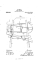
- Figure 1 is a plan view of the improved machine.
- Fig. 2 is a detail in right side elevation, showing a portion of the machine.
- Fig. 3 is a detail in side elevation, showing the upper and lower sections of the upper gang of sieves.
- Fig. 4 is a view in left side elevation, with some parts broken away, showing the improved machine; and
- Fig. 5 is a vertical section taken through the machine on the line m of Fig. 1.
- the framework of the machine is indicated as an entirety by the numeral 1. At its upper portion, this framework supports a feed hopper 2 having in its bottom a discharge opening 3 adapted to be closed and to be opened to any desired extent by a sliding gate or valve 4 of the usual or any suitable construction.
- an upper sieve shoe 5 Mounted to vibrate between the sides of the framework 1, below the hopper 2, is an upper sieve shoe 5, which shoe, near its receiving end, is supported by a pair of yielding metal straps 6 secured thereto at their lower ends, and secured at their upper ends to extended side boards 2 of the hopper 2.
- the shoe 5 is supported by a pair of upwardly extended arms 7 secured on a rock shaft 8, journaled in suitable hearings on the sides of the frame 1.
- the said arms 7 are pivotally connected to brackets 9 secured on the sides of the shoe 5.
- the said rock shaft 8 is provided at one end with an upwardly extended arm 10, and near each end it is provided with Specification of Letters Patent.
- the shoe 5 In the preferred arrangement of the shoe 5, it is provided with three imperforate inclined feed decks 12, 13and 14.
- the feed deck 12 directly underlies the discharge opening 3 of the hopper 2; the deck 13 6X- tends from a point below the deck 12 to the intermediate portion of the shoe 5; and the deck '14 extends below and forward of said deck 13.
- the shoe 5 At the lower portion of its delivery end, the shoe 5 is provided with a transverse supporting bar 15.
- the shoe 5 is provided with a gang of sieves connected in two banks or groups, as best shown in Figs. 3 and 5, wherein the numerals 16 and 17 indicate, respectively, the sieve surfaces and frames of the sieves, and the numerals 18 and 19 indicate, respectively, the sieve surfaces and frames of the.
- the frames 17 are provided with narrow transverse deck sections 17 and at their lower portions they are provided with similar deck sections 17
- the frames 19 at their upper ends are provided with narrow transverse deck sections 19*, and at their lower ends they are provided with similar deck sections 19'.
- the upper ends of the sides of the upper frame 17 are notched at 22 for inter locking engagement with the lower edge of the deck 12, and the sides of the upper frame 19 are provided with raised lock blocks 21 that engage the lower ends of the sides of the lowermost sieve frame 17, and thus secure in working position the upper bank of sieves 1617.
- the lower sieve shoe 23 is supported by the depending arms 11 of the rock shaft 8 and by a pair of pivoted links 24, pivoted to the sides of said shoe 23 and to the sides of the frame 1. This lower shoe 23 is provided with one or more inclined sieves 25, and below said sleeve with an imperforate deck 26.
- a fan case 27 Secured to the frame 1 below the receiving end of the upper shoe 5, is a fan case 27 in which works a fan head 28, the shaft 29 of which projects outward and is provided at one end with a spur pinion 30, and at its other end with a crank disk 31.
- the crank disk 31 is connected by a pitman or connecting rod 32, to the upper end of the arm 10 of the rock shaft 8.
- the spur pinion 3O meshes with a large spur gear 33 suitably journaled on the adjacent side of the frame 1, and provided with a hand crank 34, by means of which it may be rotated.
- the fan case 27 is so positioned, and the discharge opening thereof is so arranged that air blown from the fan case, under the rotation of the fan head 28, will blow air above the lower deck 14 of the shoe 5, and out through the passages between the sieves of the lower section of said upper shoes.
- 14* indicates a deflecting board which, as shown, is secured to the sides of the frame 1 and is arranged to prevent the discharge of air from the fan below the deck 14.
- the deck 13 prevents the passage of air between the sieves of the upper group or section of the gang of sieves in the upper shoe 5.
- the arrangement whereby the fan is caused to blow a blast of air through the spaces between several of the lower sieves of the gang in said shoe I believe to be new and desire to claim the same broadly.
- the intermediate portion of the shoe 23 is arranged to strike against a sto bar 35, the ends of which are secured to t e sides of the frame 1.
- the arrangement should, of course, be such that the shoe 23 will strike said stop bar 35 only when it has reached approximately the limit of its downward movement.
- the upper and lower groups of sieves in the u per shoe may be used independently or toget er, according to the kind of work required.
- the sieves of the upper group would usually be provided with perforations that are larger than those in the sieves of the lower group.
- the u per group of sieves 1617 may be used a one for separating macaroni wheat which is large, from oats and other grain.
Landscapes
- Combined Means For Separation Of Solids (AREA)
Description
W. SPERRY.
GRAIN SEPARATOE. APPLICATION FILED FEB-.16, 1907.
29 4 Patented July 27,1909. I v I 3BEEBTS-BBFET 1.
By, 1 j0 .1: Emu r=H932 90o oooooa a o o 0% 0 0 0 0 0 0 0 0 0 o q 0 O O D 0 0 0 0 0 9 W. SPERM GRAIN SEBARATOR. APPLICATION FILED IBBJG, 190 7.
929,044, Patented July 27, 1909.
I SS-HEETS SHEFI 2.
WLSPERRY.
GRAIN SEPARATOR.
APPLICATION TILED 21:13.16, 1901.
Patented July 27, 1909. 3 SHEETS-SHEET 3.
don/4m mnnzw. s. muum co PMovo-u'mucnwnzns. WASHINGTON. a. c.
UNITED STATS raanr @FFICE WILLIS SPERRY, OF OWATONNA, MINNESOTA.
GRAIN-SEPARATOR.
To all whom it may concern:
Be it known that I, NILLIS SPERRY, a citizen of the United States, residing at Owatonna, in the county of Steele and State of Minnesota, have invented certain new and useful Improvements in Grain-Separators; and I do hereby declare the following to be a full, clear, and exact description of the invention, such as will enable others skilled in the art to which it appertains to make and use the same.
My invention has for its object to provide an improved grain separator, and to this end it consists of the novel devices and combinations of devices hereinafter described and defined in the claims.
The invention is illustrated in the accompanying drawings, wherein like characters indicate like parts throughout the several. views.
Referring to the drawings, Figure 1 is a plan view of the improved machine. Fig. 2 is a detail in right side elevation, showing a portion of the machine. Fig. 3 is a detail in side elevation, showing the upper and lower sections of the upper gang of sieves. Fig. 4 is a view in left side elevation, with some parts broken away, showing the improved machine; and Fig. 5 is a vertical section taken through the machine on the line m of Fig. 1.
The framework of the machine is indicated as an entirety by the numeral 1.. At its upper portion, this framework supports a feed hopper 2 having in its bottom a discharge opening 3 adapted to be closed and to be opened to any desired extent by a sliding gate or valve 4 of the usual or any suitable construction.
Mounted to vibrate between the sides of the framework 1, below the hopper 2, is an upper sieve shoe 5, which shoe, near its receiving end, is supported by a pair of yielding metal straps 6 secured thereto at their lower ends, and secured at their upper ends to extended side boards 2 of the hopper 2. At or near its outer end, the shoe 5 is supported by a pair of upwardly extended arms 7 secured on a rock shaft 8, journaled in suitable hearings on the sides of the frame 1. As shown, the said arms 7 are pivotally connected to brackets 9 secured on the sides of the shoe 5. The said rock shaft 8 is provided at one end with an upwardly extended arm 10, and near each end it is provided with Specification of Letters Patent.
7 Application filed February 16, 1907.
Patented July 27, 1909.
Serial No. 357,698.
a depending arm 11, the purposes of which arms will presently be noted.
In the preferred arrangement of the shoe 5, it is provided with three imperforate inclined feed decks 12, 13and 14. The feed deck 12 directly underlies the discharge opening 3 of the hopper 2; the deck 13 6X- tends from a point below the deck 12 to the intermediate portion of the shoe 5; and the deck '14 extends below and forward of said deck 13. At the lower portion of its delivery end, the shoe 5 is provided with a transverse supporting bar 15. Also in the preferred arrangement, the shoe 5 is provided with a gang of sieves connected in two banks or groups, as best shown in Figs. 3 and 5, wherein the numerals 16 and 17 indicate, respectively, the sieve surfaces and frames of the sieves, and the numerals 18 and 19 indicate, respectively, the sieve surfaces and frames of the. lower group of sieves. At their upper portions, the frames 17 are provided with narrow transverse deck sections 17 and at their lower portions they are provided with similar deck sections 17 The frames 19 at their upper ends are provided with narrow transverse deck sections 19*, and at their lower ends they are provided with similar deck sections 19'.
Secured to the inner surface of the sides of the shoe 5 below the delivery end of the deck 13 are supporting blocks 20. Secured to the sides of the lower frame 19, just below the lowermost deck section 19 thereof, are look blocks 21. When the lower bank of sieves 1 S1 9 is applied in workin position, it v is secured to or interlocked with theshoe 5, and this is done by placing the projecting upper end of the uppermost sieve frame 19 upon the supporting blocks 20 and forcing the transverse deck section 19 thereof under the delivery end of the deck 13, and by forc ing the delivery ends of the said connected frames 19 downward so that the lock blocks 21 engage with the supporting bar 15, and the lower deck section 19 rests upon said bar 15. The upper ends of the sides of the upper frame 17 are notched at 22 for inter locking engagement with the lower edge of the deck 12, and the sides of the upper frame 19 are provided with raised lock blocks 21 that engage the lower ends of the sides of the lowermost sieve frame 17, and thus secure in working position the upper bank of sieves 1617. The lower sieve shoe 23 is supported by the depending arms 11 of the rock shaft 8 and by a pair of pivoted links 24, pivoted to the sides of said shoe 23 and to the sides of the frame 1. This lower shoe 23 is provided with one or more inclined sieves 25, and below said sleeve with an imperforate deck 26.
Secured to the frame 1 below the receiving end of the upper shoe 5, is a fan case 27 in which works a fan head 28, the shaft 29 of which projects outward and is provided at one end with a spur pinion 30, and at its other end with a crank disk 31. The crank disk 31 is connected by a pitman or connecting rod 32, to the upper end of the arm 10 of the rock shaft 8. The spur pinion 3O meshes with a large spur gear 33 suitably journaled on the adjacent side of the frame 1, and provided with a hand crank 34, by means of which it may be rotated. By reference to Fig. 5 it will be noted that the fan case 27 is so positioned, and the discharge opening thereof is so arranged that air blown from the fan case, under the rotation of the fan head 28, will blow air above the lower deck 14 of the shoe 5, and out through the passages between the sieves of the lower section of said upper shoes. 14* indicates a deflecting board which, as shown, is secured to the sides of the frame 1 and is arranged to prevent the discharge of air from the fan below the deck 14. The deck 13 prevents the passage of air between the sieves of the upper group or section of the gang of sieves in the upper shoe 5. The arrangement whereby the fan is caused to blow a blast of air through the spaces between several of the lower sieves of the gang in said shoe I believe to be new and desire to claim the same broadly. This arrangement is very important and it very greatly increases the efhciency. of the machine by rendering the blast effective to carry off the desired amount of light formed materials from a stock passing through and over the said sieves. It is, of course, evident that when the gear 83 is rotated, the fan head will be rotated and the two sieve shoes 5 and 23 will be simultaneously oscillated in reverse directions.
By reference to Figs. 4 and 5 it will be seen that the arms 11 and links 24 always stand in an oblique or inclined position with respect to vertical lines drawn through their pivotal supports. Hence, it follows that whenever the lower shoe 23 is oscillated toward the right with respect to Fig. 5, it will be lowered, and when oscillated toward the left with respect to said view, it will be raised.
For the pur ose of producing a jar which will clean the sieve 25, the intermediate portion of the shoe 23 is arranged to strike against a sto bar 35, the ends of which are secured to t e sides of the frame 1. The arrangement should, of course, be such that the shoe 23 will strike said stop bar 35 only when it has reached approximately the limit of its downward movement. The upper and lower groups of sieves in the u per shoe may be used independently or toget er, according to the kind of work required. The sieves of the upper group would usually be provided with perforations that are larger than those in the sieves of the lower group. The u per group of sieves 1617 may be used a one for separating macaroni wheat which is large, from oats and other grain. For the separation of succotash, (wheat and oats) best results can be obtained by using both groups of sieves in the upper shoe. It will, of course, be understood that by the several sieve surfaces 1618 the wheat and relatively long material will be worked off at the ends of the said sieve surfaces, onto the deck sections 19*, and by the latter will be discharged beyond the receiving end of the sieve 25 of the lower shoe, while the wheat or other grain passing through the several sieve surfaces 16-18 will fall onto the deck 14 and by the latter will be directed onto the said sieve 25 of the lower shoe.
What I claim is:
In a machine of the kind described the combination with a vibratory shoe provided with deck sections and transversely support ing bar and supporting blocks, of a bank of sieves having lock blocks, and a bank of sieves having lock notches, the upper end of the upper frame of the lower bank of sieves bemg engageable between said supporting blocks and the lower edge of said deck, the lower end of the lower sieve of said lower bank being rested upon said supporting bar, with the lock blocks engaging the latter, said notches in the upper frame of the upper bank of sieves being engaged with the lower edge of said deck section, and the lower ends of the lower frame of said upper bank being engaged with said lock blocks, substantially. as described.
In testimony whereof I afiix my signature in presence of two witnesses.
WILLIS SPERRY.
Priority Applications (1)
| Application Number | Priority Date | Filing Date | Title |
|---|---|---|---|
| US35769807A US929044A (en) | 1907-02-16 | 1907-02-16 | Grain-separator. |
Applications Claiming Priority (1)
| Application Number | Priority Date | Filing Date | Title |
|---|---|---|---|
| US35769807A US929044A (en) | 1907-02-16 | 1907-02-16 | Grain-separator. |
Publications (1)
| Publication Number | Publication Date |
|---|---|
| US929044A true US929044A (en) | 1909-07-27 |
Family
ID=2997469
Family Applications (1)
| Application Number | Title | Priority Date | Filing Date |
|---|---|---|---|
| US35769807A Expired - Lifetime US929044A (en) | 1907-02-16 | 1907-02-16 | Grain-separator. |
Country Status (1)
| Country | Link |
|---|---|
| US (1) | US929044A (en) |
Cited By (1)
| Publication number | Priority date | Publication date | Assignee | Title |
|---|---|---|---|---|
| US3331508A (en) * | 1964-02-28 | 1967-07-18 | Linde Maskiner Ab | Channel supports for screen frames |
-
1907
- 1907-02-16 US US35769807A patent/US929044A/en not_active Expired - Lifetime
Cited By (1)
| Publication number | Priority date | Publication date | Assignee | Title |
|---|---|---|---|---|
| US3331508A (en) * | 1964-02-28 | 1967-07-18 | Linde Maskiner Ab | Channel supports for screen frames |
Similar Documents
| Publication | Publication Date | Title |
|---|---|---|
| US27274A (en) | Graiw-sepaiiatob | |
| US886006A (en) | Seed-separator. | |
| US170936A (en) | Improvement in grain-separators | |
| US129965A (en) | Improvement in fanning-mills | |
| US905865A (en) | Combined conveyer and purifier for grain and the like. | |
| US154379A (en) | Improvement in middlings-purifiers | |
| US1133421A (en) | Device for screening grain. | |
| US668175A (en) | Grain-separator. | |
| US138407A (en) | Improvement in fanning-mills | |
| US253380A (en) | Machine for cleaning | |
| US579258A (en) | Fanning-mill | |
| US329401A (en) | Fanning-mill | |
| US910973A (en) | Grain-separator. | |
| US255982A (en) | Grain-separator | |
| US111541A (en) | Improvement in shoes for thrashers | |
| US353658A (en) | Grain-grader | |
| US569629A (en) | Fanning-mill | |
| US149850A (en) | Improvement in middlings-purifiers | |
| US410869A (en) | Fan n ing-mill | |
| US144116A (en) | Improvement in reciprocating winnowers | |
| US1341791A (en) | Grain-separator | |
| US3423A (en) | Wheat-fan | |
| US149464A (en) | Improvement in flour-bolts | |
| US578067A (en) | Fruit-grader | |
| US360361A (en) | prevost |