US9280720B2 - Apparatus, method, and computer-readable storage medium - Google Patents
Apparatus, method, and computer-readable storage medium Download PDFInfo
- Publication number
- US9280720B2 US9280720B2 US13/934,007 US201313934007A US9280720B2 US 9280720 B2 US9280720 B2 US 9280720B2 US 201313934007 A US201313934007 A US 201313934007A US 9280720 B2 US9280720 B2 US 9280720B2
- Authority
- US
- United States
- Prior art keywords
- image
- face
- feature amount
- image quality
- image data
- Prior art date
- Legal status (The legal status is an assumption and is not a legal conclusion. Google has not performed a legal analysis and makes no representation as to the accuracy of the status listed.)
- Active, expires
Links
Images


Classifications
-
- G06K9/46—
-
- G—PHYSICS
- G06—COMPUTING OR CALCULATING; COUNTING
- G06V—IMAGE OR VIDEO RECOGNITION OR UNDERSTANDING
- G06V40/00—Recognition of biometric, human-related or animal-related patterns in image or video data
- G06V40/10—Human or animal bodies, e.g. vehicle occupants or pedestrians; Body parts, e.g. hands
- G06V40/16—Human faces, e.g. facial parts, sketches or expressions
- G06V40/172—Classification, e.g. identification
-
- G06K9/00288—
-
- G06K9/00926—
-
- G06K9/036—
-
- G—PHYSICS
- G06—COMPUTING OR CALCULATING; COUNTING
- G06V—IMAGE OR VIDEO RECOGNITION OR UNDERSTANDING
- G06V10/00—Arrangements for image or video recognition or understanding
- G06V10/98—Detection or correction of errors, e.g. by rescanning the pattern or by human intervention; Evaluation of the quality of the acquired patterns
- G06V10/993—Evaluation of the quality of the acquired pattern
-
- G—PHYSICS
- G06—COMPUTING OR CALCULATING; COUNTING
- G06V—IMAGE OR VIDEO RECOGNITION OR UNDERSTANDING
- G06V40/00—Recognition of biometric, human-related or animal-related patterns in image or video data
- G06V40/50—Maintenance of biometric data or enrolment thereof
Definitions
- the present invention relates to an image processing technique of detecting and managing an object in image data.
- DSCs digital still cameras
- image data as many as several thousands or several ten thousands need to be handled nowadays.
- personal recognition is implemented by handling images based on a human's face. For example, a face region included in an input image is detected in advance, information (to be referred to as a “feature amount” hereinafter) obtained by analyzing the detected face image is extracted, and the extracted feature amount is registered. Note that the feature amount to be registered increases in accordance with the number of images to be analyzed and the number of faces included in an image.
- a database in which feature amounts are registered will be called a “dictionary” or “face dictionary”. Personal recognition becomes possible by matching between an obtained face dictionary and a feature amount obtained by analyzing a newly input image.
- the present invention provides an image processing apparatus and image processing method capable of high-accuracy recognition processing, and a computer-readable storage medium.
- an image processing apparatus comprises the following arrangement.
- an apparatus comprising: a determination unit configured to determine quality of an object in image data; an extraction unit configured to extract feature information of the object; and a registration unit configured to register, in a dictionary, the feature information extracted by the extraction unit, wherein when the quality of the object determined by the determination unit is lower than a predetermined reference, the registration unit does not register the feature information in the dictionary.
- a dictionary capable of high-accuracy recognition processing can be created.
- the present invention can implement an image processing apparatus and image processing method capable of high-accuracy recognition processing, and a program.
- FIG. 1 is a block diagram showing the hardware arrangement of an image processing apparatus
- FIG. 2 is a block diagram showing software for controlling the image processing apparatus
- FIG. 3 is a flowchart of image analysis processing
- FIG. 4 is a flowchart of image analysis processing
- FIG. 5 is a flowchart of person group generation processing
- FIG. 6 is a flowchart of automatic layout proposal processing
- FIG. 7 is a view showing a display example of person groups
- FIG. 8 is a view showing a display example of an image group in a thumbnail format
- FIG. 9 is a view showing a display example of an image group in a calendar format
- FIG. 10 is a table showing an example of attribute information obtained by image analysis
- FIG. 11 is a view showing an example of an image analysis result save format
- FIG. 12 is a table showing an example of attribute information that can be manually input by a user
- FIG. 13 is a view showing an example of a UI used to manually input the favorite rate
- FIG. 14 is a view showing an example of a UI used to manually input event information
- FIG. 15 is a view showing an example of a UI used to manually input person attribute information
- FIG. 16 is a view showing an example of a person attribute information save format
- FIG. 17 is a view showing an example of a layout template
- FIG. 18 is a view showing an example of the hold format of the layout template shown in FIG. 17 ;
- FIG. 19 is a view showing an example of a layout template
- FIG. 20 is a view showing an example of the hold format of the layout template shown in FIG. 19 ;
- FIG. 21 is a flowchart of automatic layout generation processing according to the first embodiment
- FIG. 22 is a flowchart of unnecessary image filtering processing according to the first embodiment
- FIG. 23 is a view showing an example of automatic trimming processing
- FIG. 24 is a table showing an example of layout evaluation values when performing automatic layout
- FIG. 25 is a graph for explaining a method of calculating brightness appropriateness
- FIG. 26 is a graph for explaining a method of calculating saturation appropriateness
- FIG. 27 is a view for explaining trimming loss determination processing
- FIG. 28 is a table for explaining image similarity determination processing
- FIG. 29 is a view showing a display example of an automatic layout generation result
- FIG. 30 is a view showing an example of holding a decided theme and main character information
- FIG. 31 is a view showing an example of holding a decided theme and main character information
- FIG. 32 is a view showing an example of holding generated automatic layout information
- FIG. 33 is a block diagram for explaining a face dictionary creation apparatus
- FIG. 34 is a view for explaining the internal arrangement of a face dictionary
- FIG. 35 is a flowchart showing face dictionary creation
- FIG. 36 is a flowchart showing details of face state determination processing
- FIG. 37 is a flowchart for explaining face state determination processing
- FIGS. 38A and 38B are a view and graph, respectively, for explaining face state determination processing.
- FIG. 39 is a block diagram for explaining a face dictionary creation apparatus.
- the first embodiment of the present invention will be described to automatically generate a layout output by using an input image group. This merely exemplifies a form of implementation, and the present invention is not limited to the following embodiment.
- FIG. 1 is a block diagram showing an example of the hardware arrangement of an image processing apparatus according to the first embodiment.
- an image processing apparatus 115 includes a CPU (Central Processing Unit) 100 , ROM 101 , RAM 102 , secondary storage apparatus 103 , display apparatus 104 , input apparatus 105 , IF 107 , IF 108 , and wireless LAN (Local Area Network) 109 . Further, the image processing apparatus 115 includes an internal image capturing device 106 . These units are connected to each other by a control bus/data bus 110 . The image processing apparatus 115 according to the embodiment is implemented by an information processing apparatus.
- CPU Central Processing Unit
- the image processing apparatus 115 is, for example, a computer 115 .
- the CPU 100 executes information processing to be described in the first embodiment in accordance with programs such as an application.
- the CUP 101 loads a program stored in a hard disk or the like to a RAM 102 and runs the program on the RAM 102 , thereby controlling of the entire image arrangement control apparatus according to the present embodiment.
- the ROM 101 stores programs to be executed by the CPU 100 .
- the RAM 102 provides a memory to temporarily store various kinds of information when the CPU 100 executes the programs.
- the secondary storage apparatus 103 is a hard disk or the like and serves as a storage medium to save, for example, a database that saves image files and image analysis results.
- the display apparatus 104 is, for example, a display and is an apparatus which presents, to the user, various kinds of UIs (User Interfaces) to be described below, including a processing result in the embodiment.
- the display apparatus 104 may have a touch panel function.
- the control bus/data bus 110 connects the above-described units to the CPU 100 .
- the image processing apparatus 115 also includes the input apparatus 105 such as a mouse or keyboard used by a user to input an image correction processing instruction and the like.
- the image processing apparatus 115 may include the internal image capturing device 106 . An image captured by the internal image capturing device 106 undergoes predetermined image processing and is saved in the secondary storage apparatus 103 .
- the image processing apparatus 115 may load an image from an external image capturing device 111 connected via an interface (IF 108 ).
- the image processing apparatus 115 also includes the wireless LAN 109 , which is connected to Internet 113 .
- the image processing apparatus 115 can also acquire image data from an external server 114 connected to the Internet 113 .
- a printer 112 for outputting an image and the like is connected to the image processing apparatus 115 via the IF 107 .
- the printer 112 is further connected to the Internet and can exchange print data via the wireless LAN 109 .
- FIG. 2 is a block diagram showing a software arrangement including the above-described application according to the first embodiment.
- Image data acquired by the image processing apparatus 115 is normally compressed in a compression format such as JPEG (Joint Photography Expert Group).
- a compression format such as JPEG (Joint Photography Expert Group).
- an image codec part 200 decompresses image data based on the compression format and converts it into image data (bitmap data) in a so-called RGB dot-sequential bitmap data format.
- the converted bitmap data is transferred to a display and UI control part 201 and displayed on the display apparatus 104 such as a display.
- the bitmap data is further input to an image sensing part 203 (application), and undergoes various analysis processes (details will be described later) by the image sensing part 203 .
- image sensing part 203 application
- Various kinds of attribute information of the image obtained by the analysis processing are stored in the secondary storage apparatus 103 by a database part 202 (application) in accordance with a predetermined format. Note that image analysis processing and sensing processing will be handled in the same sense.
- a scenario generation part 204 (application) generates the conditions of a layout to be automatically generated in accordance with various conditions input by the user, details of which will be described later.
- a layout generation part 205 performs processing of automatically generating a layout for arranging image data in accordance with the generated scenario.
- a rendering part 206 renders the generated layout into bitmap data for display.
- the bitmap data serving as the rendering result is transmitted to the display and UI control part 201 , and its contents are displayed on the display apparatus 104 .
- the rendering result is also transmitted to a print data generation part 207 , and the print data generation part 207 converts it into printer command data and transmits the command to the printer 112 .
- FIGS. 3 and 4 are flowcharts each showing processing to be executed by the image sensing part 203 .
- FIGS. 3 and 4 each show processing of acquiring a plurality of image data groups, performing analysis processing for each image data group, and storing the result in the database part 202 .
- FIG. 5 shows person group generation processing of grouping face information supposed to be of the same person based on detected face position information.
- FIG. 6 shows processing of deciding a scenario for layout creation based on image analysis information and various kinds of information input by the user, and automatically generating a layout based on the scenario.
- the image sensing part 203 acquires an image data group.
- the user connects, to the image processing apparatus 115 , an image capturing apparatus or memory card which stores captured images, and loads the captured images from it, thereby acquiring an image data group.
- images which have been captured by the internal image capturing device 106 and stored in the secondary storage apparatus 103 may be acquired.
- the image data group may be acquired via the wireless LAN 109 from an apparatus other than the image processing apparatus 115 , such as the external server 114 connected to the Internet 113 .
- a display on the display apparatus 104 upon acquiring an image data group will be explained with reference to FIGS. 8 and 9 .
- the UI on the display apparatus 104 changes to a display which allows the user to confirm images based on the acquired image data, as shown in FIGS. 8 and 9 .
- the UI display method on the display apparatus 104 is not particularly limited as long as an image can be confirmed.
- thumbnails 802 of images may be displayed on a UI 801 for each folder in the secondary storage apparatus 103 , as shown in FIG. 8 .
- image data may be managed for each date of a calendar on a UI 901 , as shown in FIG. 9 .
- images captured at the clicked date are displayed in a thumbnail list as shown in FIG. 8 .
- steps S 302 to S 305 analysis processing and database registration of the analysis result are performed for each acquired image data group.
- the number of person's faces (int: value 0 or more (0 to MAXFACE)) and coordinate positions (int*8: value 0 or more (same for Width and Height)) representing position information of a person's face are analyzed. Further, the average Y (int: value 0 to 255) in a face region, the average Cb (int: value ⁇ 128 to 127) in the face region, and the average Cr (int: value ⁇ 128 to 127) in the face region are analyzed.
- an object's face is a person's face in the embodiment, but the object may be the face of an animal such as a pet.
- the average luminance and average saturation of an entire image which are basic feature information of an image such as image feature amounts, can be calculated by a known method and will therefore be described briefly.
- the R, G, and B components of each pixel of an image are converted into known luminance and color difference components (for example, Y, Cb, and Cr components), and the average value of the Y components is calculated.
- the average hue AveH in an image is a feature amount to evaluate the tone of the image.
- the hue of each pixel can be obtained using a known HIS transformation.
- the values are averaged in the entire image, thereby obtaining AveH.
- the feature amounts may be calculated for an entire image. Alternatively, for example, an image may be divided into regions having a predetermined size, and the feature amounts may be calculated for each region.
- a flesh color region is detected from an image.
- a human iris color pixel is then detected in the flesh color region, thereby detecting the position of an eye.
- the matching level between an image and each of a plurality of face shape templates is calculated.
- a template having a highest matching level is selected. If the highest matching level is equal to or more than a predetermined threshold, a region on the selected template is set as a face candidate region. By using this template, the position of an eye can be detected.
- a nose image pattern is set as a template, and an entire image or a designated region of an image is scanned. A position that matches the template most is output as the position of the nose. Then, a region above the nose position in the image is assumed to be a region where the eyes exist. The eye existence region is scanned using an eye image pattern as a template, and matching is calculated. A set of pixels whose matching levels are higher than a given threshold is acquired as an eye existence candidate position. A continuous region included in the eye existence candidate position set is divided into clusters. The distance between each cluster and the nose position is calculated. A cluster having a shortest distance is decided as a cluster including an eye, thereby detecting the organ position.
- known methods of detecting a face and organ positions are usable, including methods described in Japanese Patent Laid-Open Nos. 8-77334, 2001-216515, 5-197793, 11-53525, 2000-132688, 2000-235648, and 11-250267, and Japanese Patent No. 2541688.
- the number of person's faces and the coordinate positions of each face can be acquired.
- the average luminance and average color differences of the face region can be obtained by calculating, for each face region, the average Y, Cb, and Cr values of pixel values included in the face region.
- sensing information is not limited to that acquired by the above-described sensing processing, and any other sensing information may be used.
- the image sensing part 203 stores, in the database part 202 , the sensing information acquired in the above-described manner.
- the save format in the database part 202 is not particularly limited.
- the sensing information is described using, for example, a general-purpose format (for example, XML: eXtensible Markup Language) as shown in FIG. 11 and stored.
- a general-purpose format for example, XML: eXtensible Markup Language
- FIG. 11 shows an example in which pieces of attribute information of each image are classified into three categories and described.
- the first ⁇ BaseInfo> tag is information added to an acquired image file in advance and representing the image size and capturing time information.
- This tag includes the identifier ID (ID) of each image, the save location ( ⁇ ImagePath>) where the image file is stored, the image size ( ⁇ ImageSize . . . >), and the capturing date & time ( ⁇ CaptureDateTime>).
- the second ⁇ SensInfo> tag is used to store the result of the above-described image analysis processing.
- the average luminance, average saturation, and average hue of an entire image and the scene analysis result are stored.
- information associated with the face position and face color of a person present in the image can be described.
- the third ⁇ UserInfo> tag can store information input by the user for each image, details of which will be described later.
- the method of storing attribute information of an image in the database part 202 is not limited to the above-described one, and any other known format is usable.
- step S 305 the image sensing part 203 determines whether unprocessed image data in the acquired image data group is the final image data. If the unprocessed image data is not the final image data (NO in step S 305 ), the process returns to step S 302 , and the image sensing part 203 acquires the unprocessed image data from the acquired image data group. If the unprocessed image data is the final image data (YES in step S 305 ), the process advances to step S 306 .
- step S 306 the image sensing part 203 performs person grouping by using personal recognition processing.
- person group generation processing is generated to generate a group of each person by using the face position information detected in step S 303 . Automatically grouping person's faces in advance makes work efficient to name each person later by the user.
- the person group generation processing is executed using a personal recognition technique according to the flowchart of FIG. 5 .
- the personal recognition technique is mainly formed from two techniques, that is, extracting the feature amounts of organs such as an eye and mouth existing in a face and comparing the similarities of the relationships between them.
- a known method is usable, as disclosed in Japanese Patent No. 3469031.
- FIG. 5 is a flowchart showing details of step S 306 .
- step S 501 the image sensing part 203 sequentially reads out and decodes image data stored in the secondary storage apparatus 103 .
- the decoding processing is the same as step S 302 , and a description thereof will not be repeated.
- step S 502 the image sensing part 203 accesses the database part 202 to acquire the number of faces included in the image data and face position information.
- step S 504 the image sensing part 203 generates a normalized face image to perform personal recognition processing.
- the normalized face images are face images obtained by extracting faces existing in images with various sizes, orientations, and resolutions, and converting and cutting out them into faces having a predetermined size and orientation. Since the positions of organs such as an eye and mouth are important to perform personal recognition, the normalized face image has a size enough to reliably recognize the organs. By preparing the normalized face images, feature amount extraction processing need not cope with faces of various resolutions.
- step S 505 the image sensing part 203 extracts a face feature information such as face feature amounts from the normalized face image.
- the face feature amounts include the positions and sizes of organs such as an eye, mouth, and nose, and the outline of the face.
- the image sensing part 203 refers to a face dictionary which is built in the database part 202 and stores face feature amounts prepared in advance for each person identifier (person ID), and determines whether face feature amounts stored in the face dictionary are similar to the extracted face feature amounts.
- person ID person identifier
- face feature amounts are not registered in some cases, as shown in FIGS. 33 and 35 , details of which will be described later.
- the image sensing part 203 determines that the stored face feature amounts are similar to the extracted ones (YES in step S 506 ), it additionally registers the extracted feature amounts as additional feature amounts of the same (or similar) person in the entry of the corresponding person ID in step S 509 .
- the image sensing part 203 determines that the stored face feature amounts are not similar to the extracted ones (NO in step S 506 ), the feature amounts of the currently evaluated face are considered to be of a person different from those registered in the face dictionary until now in step S 508 . Thus, the image sensing part 203 issues a new person ID, and newly registers the feature amounts in the face dictionary. In the embodiment, the feature amounts of a face determined to be in a poor face state in face state determination are not registered in the dictionary.
- step S 510 the image sensing part 203 determines whether there is another face region in the processing target image data. If there is another face region (YES in step S 510 ), the process returns to step S 502 . If there is no other face region (NO in step S 510 ), the process advances to step S 511 .
- step S 511 the image sensing part 203 determines whether the processes in steps S 502 to S 509 have ended for all images. If the processes have ended for all images, the process ends. If the processes have not ended for all images, the process returns to step S 502 . That is, the image sensing part 203 applies the processes in steps S 502 to S 509 to all face regions detected from the acquired image data group, and groups appearing persons.
- person group generation processing is executed after the end of sensing processing and database registration of all image data, as shown in FIG. 3 .
- another method may be adopted. For example, as shown in FIG. 4 , after each image data undergoes sensing processing and is registered in the database in step S 403 , person group generation processing is executed in step S 405 using face position information. All image data are processed by repeating these processes.
- FIG. 7 shows display of each person group according to the embodiment.
- reference numeral 702 denotes a representative face image of the person group.
- a region 703 exists and displays the name of the person group.
- a person name “No name” is displayed in the region 703 , as shown in FIG. 7 .
- a plurality of face images included in the person group are displayed.
- a person name can be input by designating the “No name” region 703 , or information such as the birthday or family relationship can be input for each person, as will be described later.
- FIG. 12 shows a list of examples of the attribute information.
- the manually or automatically registered attribute information is roughly divided into image attribute information set for each image and person attribute information set for each person grouped by person grouping processing.
- An example of the image attribute information is the favorite rate of the user.
- the user can manually input the favorite rate representing whether he likes the image. For example, as shown in FIG. 13 , the user selects a thumbnail image 1302 he wants on a UI 1301 by using a mouse pointer 1303 and right-clicks to display a dialog capable of inputting the favorite rate.
- the user can select the number of “ ⁇ ”s in the menu in accordance with his preference. In the embodiment, it is set to increase the number of “ ⁇ ”s as the favorite rate is higher.
- the favorite rate may be set not manually by the user but automatically. For example, the number of times of viewing by the user may automatically be set as the favorite rate. Assume that the user clicks on a thumbnail (image file) he wants, and the state of the thumbnail image list display (UI 801 ) shown in FIG. 8 changes to a single image display screen. The transition count may be measured to automatically set the favorite rate in accordance with the count. That is, it is determined that the user likes the image much more as the number of times of viewing is larger.
- the favorite rate is manually set by the user or automatically set based on the number of times of viewing or the number of times of printing.
- Another attribute information set for each image is event information.
- Examples of the event information are the family travel “travel”, graduation ceremony “graduation”, and wedding “wedding”.
- the user may designate a date he wants on a calendar represented on a UI 1401 of FIG. 14 using a mouse pointer 1402 , and input the name of the event on that day.
- the designated event name (event information) is included in the XML format shown in FIG. 11 as part of the image attribute information.
- the event name and image are associated (linked) with each other using an ⁇ Event> tag in the ⁇ UserInfo> tag.
- FIG. 15 shows a UI 1501 for inputting person attribute information.
- reference numeral 1502 denotes a representative face image of a predetermined person (in this case, “father”).
- Reference numeral 1503 denotes a region where the name of the predetermined person is displayed.
- 1504 a list of images which are detected from other images and are determined in step S 506 to have similar face feature amounts is displayed.
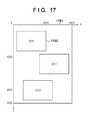
- Each layout template includes a plurality of image arrangement frames 1702 , or 1902 and 1903 (to be synonymous with slots hereinafter) on a sheet 1701 or 1901 to lay out images.
- Such layout templates are saved in the secondary storage apparatus 103 in advance when the software to execute the first embodiment is installed in the image processing apparatus 115 .
- an arbitrary layout template may be acquired from the external server 114 present on the Internet 113 connected via the IF 107 or wireless LAN 109 .
- FIGS. 18 and 20 show examples of XML data for the layout templates in FIGS. 17 and 19 .
- a ⁇ BASIC> tag describes basic information of a layout template.
- the basic information includes, for example, the theme of the layout template, the page size, and the page resolution (dpi).
- a ⁇ Theme> tag representing the theme of the layout template is blank in the initial state of the layout template.
- the page size ( ⁇ PageSize> tag) is set to A4, and the resolution ( ⁇ Resolution> tag) is set to 300 dpi.
- the ⁇ ImageSlot> tag can also set, for each slot, the shape of the slot and the name of a recommended person group to be arranged.
- the ⁇ Shape> tag of FIG. 18 describes a rectangular shape (“rectangle”) for all slots, and the ⁇ PersonGroup> tag recommends to arrange “MainGroup” as the person group name.
- the application according to the embodiment performs, at a predetermined timing, processing of automatically generating a collage layout the user is likely to be fond of, and presenting it to the user (to be referred to as layout proposal processing hereinafter).
- FIG. 6 shows the basic flowchart of the layout proposal processing.
- the scenario generation part 204 decides the scenario of proposal processing.
- the scenario includes the theme of a layout to be proposed, a layout template, setting of a person (main character) to be emphasized in the layout, and selection information of an image group to be used for layout generation.
- the theme of the layout to be proposed is decided as the growth record “growth”.
- a template is selected.
- a layout template as shown in FIG. 19 suitable for the growth record is selected, and “growth” is described in the ⁇ Theme> tag of XML, as shown in FIG. 30 .
- “son” is set as the main character “MainGroup” on which focus is placed at the time of layout.
- “son” and “father” are set as “SubGroup” on which focus is secondarily placed at the time of layout.
- An image group to be used for layout is selected.
- the database part 202 is referred to, and images including “son” are extracted and listed out of the images captured so far from the birthday of the person “son”.
- the image list generated by the listing is stored and managed in the database part 202 .
- the scenario decision for the growth record layout has been described.
- the scenario generation part 204 decides a scenario to propose a layout of the family travel.
- the theme of the layout to be proposed is decided as the travel “travel”.
- a layout template is selected.
- a layout template as shown in FIG. 17 is selected, and “travel” is described in the ⁇ Theme> tag portion of XML, as shown in FIG. 31 .
- step S 603 of FIG. 6 the layout generation part 205 executes automatic layout generation processing based on the above-described scenario.
- the automatic layout generation processing based on the scenario will be described here with reference to FIG. 21 .
- FIG. 21 shows the detailed processing sequence of the layout processing part.
- step S 2101 the layout generation part 205 acquires, from the database part 202 , layout template information 202 c after the layout theme and the person group information decided by the scenario are set.
- the layout generation part 205 acquires the feature amounts of each image from the database part 202 based on an image group list 202 d decided by the scenario, and generates an image group attribute information list.
- the image group attribute information list has a structure in which the ⁇ IMAGEINFO> tags shown in FIG. 11 are arranged as many as the number of image lists.
- the layout generation part 205 performs the automatic layout generation processing in steps S 2105 to S 2109 based on the image group attribute information list.
- attribute information stored in the database part 202 by performing sensing processing in advance for each image is used, instead of directly handling the image data itself. This is because if the image data itself is used when performing the layout generation processing, a very large memory area is required to store the image group. The utilization of the memory area can be reduced by using the attribute information stored in the database part 202 , as in the embodiment.
- step S 2105 the layout generation part 205 filters unnecessary images from the input image group by using the attribute information of the input image group.
- the filtering processing will be explained with reference to FIG. 22 .
- FIG. 22 is a flowchart of the filtering processing.
- step S 1601 the layout generation part 205 determines for each image whether the average luminance value AveY of the entire image falls within the range of predetermined thresholds ThY_Low and ThY_High. If the average luminance value AveY falls outside the range (NO in step S 1601 ), the process advances to step S 1606 , and the layout generation part 205 removes the image of interest from the layout target image.
- the average luminance and color difference components for example, AveY, AveCb, and AveCr components
- step S 1605 the layout generation part 205 determines whether the face is the final face. If the face is not the final face, the process returns to step S 1602 . If the face is the final face, the process ends.
- the thresholds are desirably set relatively leniently. For example, in the overall image luminance determination of step S 1601 , if the difference between ThY_High and ThY_Low is much smaller than the image dynamic range, the number of images determined as “YES” accordingly decreases. Hence, in the filtering processing of the embodiment, the difference between the thresholds is set as large as possible. In addition, thresholds which can remove an image that is obviously determined as an abnormal image are set.
- step S 2107 of FIG. 21 the layout generation part 205 generates an enormous number of (L) temporary layouts by using the image group determined as the layout target by the above-described processing of FIG. 22 .
- Temporary layout generation is executed by repeating processing of arbitrarily applying an input image to an image arrangement frame of the acquired template. At this time, the following parameters (image selection, arrangement, and trimming criterion) are decided at random.
- the image selection defines, for example, an image which should be selected from the image group when N image arrangement frames exist in the layout.
- the arrangement defines, for example, arrangement frames in which a plurality of selected images should be arranged.
- the trimming criterion defines a trimming ratio representing the degree of trimming processing to be performed for an arranged image.
- the trimming ratio is represented by, for example, 0% to 100%.
- An image is trimmed using the center of the image as the reference, as shown in FIG. 23 .
- reference numeral 2301 denotes an entire image; and 2302 , a cutting frame for trimming at a trimming ratio of 50%.
- the generated temporary layouts can be expressed by XML, as shown in FIG. 32 .
- the ID of the image selected and arranged in each slot is described by the ⁇ ImageID> tag, and the trimming ratio is described by the ⁇ TrimingRatio> tag.
- the number L of temporary layouts generated here is decided in accordance with the throughput of evaluation processing in a layout evaluation step to be described later and the performance of the image processing apparatus 115 that performs the processing. For example, several hundred thousand or more different temporary layouts are prepared.
- Each generated layout can be saved together with an ID in the secondary storage apparatus 103 as a file using the XML format shown in FIG. 32 , or stored in the RAM 102 using another data structure such as a structure.
- FIG. 24 shows a list of layout evaluation amounts according to the embodiment. As shown in FIG. 24 , the layout evaluation amounts used in the embodiment can be mainly divided into three categories.
- the first evaluation category includes the evaluation amounts of each image.
- the evaluation amounts are used to determine states such as the brightness, saturation, and blur amount of an image and score the states.
- states such as the brightness, saturation, and blur amount of an image and score the states.
- An example of scoring will be described below.
- the score is set to be lower when the average luminance falls outside the predetermined threshold range.
- the saturation appropriateness scores 100 when the average saturation of the entire image is larger than a predetermined saturation value, as shown in FIG. 26 .
- the score is set to gradually decrease when the average saturation is smaller than the predetermined value.
- the second evaluation category targets evaluation of matching between an image and a slot (image/slot matching evaluation).
- the image/slot matching is determined and scored. Examples of evaluation of the image/slot matching are person matching and trimming loss determination.
- the person matching represents the matching ratio of a person designated for a slot to a person who exists in an image actually arranged in the slot. For example, assume that “father” and “son” are designated for a slot as “PersonGroup” designated by XML. At this time, when the two persons are included in the image assigned to the slot, the person matching of the slot scores 100. If only one of the persons is included, the matching scores 50. If neither person is included, the matching scores 0.
- the matching in a slot is the average value of matchings calculated for respective slots.
- the third evaluation category evaluates the balance in a layout page (in-page balance evaluation).
- FIG. 24 shows image similarity, tone variation, and face size variation as the evaluation values used to evaluate the balance.
- MinInterval is calculated for each of the L temporary layouts and stored in an array stMinInterval[l].
- a maximum value MaxMinInterval in stMinInterval[l] is calculated.
- Similarity[l] is effective as the image similarity evaluation value because it comes close to 100 as the minimum capturing time interval becomes large, and close to 0 as the time interval becomes small.
- ColorVariance[l] is effective as the tone variation evaluation value because it comes close to 100 as the variation of the average hues of images arranged in a page becomes large, and close to 0 as the variation of the average hues becomes small.
- EvalLayout[l] be the integrated evaluation value of the lth temporary layout
- EvalValue[n] be N evaluation values (including the evaluation values shown in FIG. 24 ) calculated above.
- the integrated evaluation value can be obtained by
- W[n] is the weight of each evaluation value shown in FIG. 24 for each scene.
- a different weight is set for each layout theme. For example, the themes of the growth record “growth” and travel “travel” are compared, as shown in FIG. 24 . For the travel “travel”, a number of photos whose quality is as high as possible are laid out in a variety of scenes, and settings are done with a tendency to emphasize the individual evaluation values of the images and the in-page balance evaluation values. On the other hand, for the growth record “growth”, whether the main character as the growth record target properly matches each slot is more important than the image variation, and settings are done with a tendency to emphasize the image/slot matching evaluation than in-page balance or the individual evaluation of images.
- step S 2109 the layout generation part 205 generates a layout list LayoutList[k] for layout result display by using EvalLayout[l] calculated in the above-described way.
- step S 605 of FIG. 6 the rendering part 206 renders the layout result obtained by the layout generation processing described with reference to FIG. 21 , and displays the result.
- the rendering result is displayed on a UI 2901 in FIG. 29 .
- the rendering part 206 reads out the layout identifier stored in LayoutList[ 0 ], and reads out the temporary layout result corresponding to the layout identifier from the secondary storage apparatus 103 or RAM 102 .
- the layout result as described above, template information and image names assigned to the respective slots present in the template are set.
- the rendering part 206 renders the layout result based on these pieces of information using the rendering function of the OS running on the image processing apparatus 115 , and displays the rendering result like a layout result 2902 in FIG. 29 .
- the identifier of LayoutList[ 1 ] with the next score is read out.
- the layout result is rendered and displayed in the same manner as described above. This allows the user to view variations of proposed layouts.
- the user can also redisplay the layout displayed previously by pressing a Previous button 2903 . If the user likes the displayed layout, he can press a Print button 2905 to cause the printer 112 connected to the image processing apparatus 115 to print the layout result 2902 .
- Face dictionary creation processing to be used in personal recognition will be described in detail.
- the degree of blurring of a detected face image is calculated, and the state of the face image is determined based on the calculated degree.
- FIG. 33 is a block diagram showing an example of the arrangement of a face dictionary creation apparatus for personal recognition according to the first embodiment.
- the building components of the face dictionary creation apparatus may be implemented by hardware, software which is implemented by control of the CPU 100 of the image processing apparatus 115 in FIG. 1 , or a combination of the hardware and software.
- An image input part 3301 rasterizes input image data in the RAM 102 .
- a face detection part 3302 detects a face in the image data in the RAM 102 that has been processed by the image input part 3301 .
- the face detection processing has been described in background sensing and database registration.
- a face feature amount extraction part 3303 receives the image data input from the image input part 3301 , and the face detection position detected by the face detection part 3302 .
- the face feature amount is a face feature amount vector which represents a frequency response to each organ, but another feature amount is usable.
- a face dictionary reading part 3304 searches for face dictionary data present at a designated location in the secondary storage apparatus 103 . If there is a face dictionary created in advance, the face dictionary reading part 3304 reads it. If there is no face dictionary created in advance, the face dictionary reading part 3304 does not perform face dictionary reading processing. Face feature amount vectors are registered in the face dictionary.
- the face dictionary save location is a designated location in the secondary storage apparatus 103 in the embodiment, but may be another location. In reading data, the face dictionary reading part 3304 analyzes dictionary data and sets the number of registered face feature amount vectors.
- FIG. 34 is a view showing the inside of the face dictionary.
- An ID 3401 represents a person identifier. The number of IDs is not particularly limited and changes in accordance with the number of persons and other settings.
- a category (classification) 3402 categorizes and manages feature amounts in accordance with a standard set manually or automatically. In the embodiment, feature amounts are categorized and managed in accordance with, for example, the age for each person. The number of categories may change depending on the ID.
- a face feature amount vector group 3403 manages face feature amount vectors extracted by the face feature amount extraction part 3303 . In FIG. 34 , a face feature amount vector group 3404 is managed for each category.
- a similarity determination part 3305 receives the face feature amount extracted by the face feature amount extraction part 3303 , and the face dictionary data read by the face dictionary reading part 3304 .
- the similarity determination part 3305 determines a similarity by comparing (matching processing), as similarities, distances between the face feature amount vector extracted by the face feature amount extraction part 3303 and face feature amount vectors registered in the face dictionary. Similarity determination is performed as a round-robin in each category for each ID in FIG. 34 .
- a similarity corresponding to the shortest distance between the face feature amount vector extracted by the face feature amount extraction part 3303 and a face feature amount vector registered in the face dictionary data is output as a similarity result.
- a face dictionary ID having the shortest distance from the extracted face feature amount vector, and the distance are output. If the distance calculated as a similarity is equal to or smaller than a predetermined threshold (in other words, the similarity between a face feature vector and another face feature amount vector falls within a predetermined similarity range), the similarity determination part 3305 determines that these face feature amount vectors represent the same person. If the similarity determination part 3305 determines that these face feature amount vectors represent the same person, it sends back the same ID as that of a person determined to be the same. If the calculated distance is larger than the predetermined threshold, the similarity determination part 3305 determines that these face feature amount vectors represent anotherperson. If the similarity determination part 3305 determines that these face feature amount vectors represent anotherperson, an unused new ID is assigned. Note that similarity determination is not limited to this method, and another similarity determination method may be used for the determination.
- a face state determination part 3306 receives the image data input from the image input part 3301 , and face image data detected by the face detection part 3302 , and determines the degree of blurring (scale representing a state) of the face image of the detected face image data.
- a person group display part 3307 displays a person group.
- the result of determination by the face state determination part 3306 is NG (the scale representing a state is lower than the threshold), that is, the state of the face image is poor, the person group display part 3307 does not display a person group.
- a face dictionary registration part 3308 receives the face feature amount extracted by the face feature amount extraction part 3303 and the identifier (ID) obtained by the determination by the similarity determination part 3305 , and registers them in the face dictionary in association with a predetermined ID and the extracted face feature amount.
- FIG. 35 is a flowchart showing processing by the face dictionary creation apparatus according to the first embodiment.
- step S 3501 the image input part 3301 inputs an image and rasterizes it in the RAM 102 .
- step S 3502 the face detection part 3302 detects a face in the image data in the RAM 102 that has been processed by the image input part 3301 .
- a provisional identifier (ID) is set for the detected face image data.
- step S 3503 the face feature amount extraction part 3303 generates a normalized face image, similar to step S 504 described above. Generation of the normalized face image is the same as that in step S 504 , and a description thereof will not be repeated.
- step S 3504 the face feature amount extraction part 3303 extracts the face feature amounts of the normalized face image based on the face detection position obtained by the face detection part 3302 .
- step S 3505 the similarity determination part 3305 performs similarity determination.
- the face dictionary reading part 3304 reads face dictionary data from a designated location in the secondary storage apparatus 103 .
- the similarity determination part 3305 calculates a similarity by comparing (matching) distances between the face feature amount vector extracted by the face feature amount extraction part 3303 and face feature amount vectors registered in the face dictionary 202 a .
- the similarity determination part 3305 calculates a similarity and performs similarity determination based on the calculated similarity.
- the setting of the provisional identifier (ID) is changed. If it is determined in the similarity determination of step S 3505 that the similarity falls outside a predetermined range, in other words, it is determined that the face feature amount vectors represent another person, an unused new ID is assigned and set instead of the provisional ID in step S 3506 . If it is determined in the similarity determination of step S 3505 that the similarity falls within the predetermined range, in other words, it is determined that the face feature amount vectors represent the same person, the same existing ID as that of a person determined to be the same is sent back, and the provisional ID is settled as a normal ID in step S 3510 .
- step S 3507 a the face state determination part 3306 determines the state of the face in the image having the new ID.
- the process advances to step S 3508 a , and the person group display part 3307 displays the image on the UI.
- the image is displayed on the person group UI 704 , as shown in FIG. 7 . That is, the image having the new ID is classified and managed for each person group, and displayed on the UI.
- the image having the new ID is displayed on the UI, it may be managed by the person group without UI display.
- step S 3513 If the face state is not good, that is, is poor, the process skips to step S 3513 .
- the face image in a poor state is excluded from registration targets of the face dictionary registration part 3308 .
- the person group display part 3307 displays the image having the existing ID on the UI.
- the image is displayed on the person group UI 704 , as shown in FIG. 7 . That is, the image having the existing ID is classified and managed for each person group, and displayed on the UI.
- the image having the existing ID is displayed on the UI, it may be managed by the person group without UI display.
- step S 3507 b the face state determination part 3306 determines the state of the face in the image having the existing ID. If the face state is good, the process advances to step S 3509 , and the face state determination part 3306 performs face dictionary registration. If the face state is not good, that is, is poor, the process skips to step S 3513 . The face image in a poor state is excluded from registration targets of the face dictionary registration part 3308 .
- step S 3509 the face dictionary registration part 3308 specifies a category for registration in accordance with the set identifier and corresponding category.
- the face feature amount vector to be processed is registered in the specified category in the face dictionary.
- step S 3512 the face dictionary creation apparatus determines whether it has performed a series of processes in steps S 3502 to S 3509 for all face detection results. If the face dictionary creation apparatus has performed a series of processes for all detection results, it advances to the next process. If the face dictionary creation apparatus has not performed a series of processes for all detection results, the process returns to step S 3503 , and the face dictionary creation apparatus executes the series of processes in steps S 3502 to S 3509 for an unprocessed face detection result.
- step S 3513 the face dictionary creation apparatus determines whether it has performed a series of processes in steps S 3502 to S 3512 for all set images. If the face dictionary creation apparatus has performed a series of processes for all images, it ends the process. If the face dictionary creation apparatus has not performed a series of processes for all images, the process returns to step S 3502 , and the face dictionary creation apparatus executes the series of processes in steps S 3502 to S 3512 for an unprocessed image.
- the number of feature amounts registered in the face dictionary and the number of images of a group displayed on the UI may differ from each other.
- the internal structure of the face dictionary in FIG. 34 and the UI display example in FIG. 7 are different as a result of comparison. This is because a face image determined to be in a poor state as a result of determination by the face state determination part 3306 is not registered in the face dictionary, but an ID is assigned in face detection and is displayed on the person group UI 704 . Since an image in a poor face state, which is unsuited to face detection, is not registered in the face dictionary, the personal recognition accuracy can be increased. Since all read images are displayed on the UI, even an image in a poor face state, which is unsuited to face detection, is displayed.
- step S 3507 a only an image which is determined to be in a good state in the face state determination of step S 3507 a is displayed on the UI in step S 3508 a in order to correctly group face feature amounts in subsequent similarity determination for the next image.
- a face state is determined after calculating a similarity and displaying the face on the UI, and the image is in a poor face state and is not registered in the dictionary, a feature amount to be registered in the dictionary becomes blank. That is, even if the image is displayed on the UI, its feature amount does not exist for a corresponding ID in the dictionary.
- no feature amount exists for the corresponding ID in the dictionary thus feature amounts cannot be compared, and another ID is newly assigned to display the image on the UI.
- FIG. 36 is a flowchart showing details of step S 3503 .
- the face state determination part 3306 determines the face state of face image data detected by the face detection part 3302 .
- the face state determination part 3306 performs filter processing at, for example, a 5 ⁇ 5 pixel size, generating a blurred image.
- the face state determination part 3306 accumulates, for each block, the difference between the signal value of the generated blurred image and that of an original image before the filter processing. More specifically, the differences of the R, G, and B components are calculated.
- the face state determination part 3306 compares the calculated difference accumulation result with a predetermined threshold.
- the face state determination part 3306 determines that the face image state is good, and the process advances to step S 3305 to be performed by the face feature amount extraction part 3303 after step S 3504 . If the difference accumulation result (scale representing a state) is smaller than the threshold, the face state determination part 3306 determines that the face image state is poor, and performs the above-described series of processes for the next unprocessed face detection result.
- the R, G, and B components are used as parameters for calculating determination.
- the present invention is not limited to this, and the luminance component may be calculated.
- the G component to which the person visual sensitivity is high may be used.
- the size of the filter for generating a blurred image is not limited to 5 ⁇ 5 pixels.
- the part of analysis is not limited to a block and may be a pixel.
- the method of determining the face state is not limited to the above-described one, and another method is available.
- this detected face image when a detected face image is in a poor state, it is excluded from processing targets of face dictionary registration.
- this detected face image can be managed as one image of a similar face image group without any problem, and thus is classified into a person group.
- the first embodiment can optimize a person group while increasing the dictionary registration accuracy.
- determination processing is performed by analyzing the degree of blurring or defocusing in determination of a face image state. That is, the face image state is determined by confirming the edge of the face image. This can increase the dictionary registration accuracy.
- a similarity determination part 3305 determines a face state by using image data whose resolution is changed so that its size becomes larger than at least the image size of detected face image data.
- face state determination processing the input image data is scaled, and the scaled image data is processed. At this time, the resolution is changed to set a size larger than the image size of at least detected face image data. Accordingly, face state determination can be performed at higher accuracy.
- FIG. 37 is a flowchart showing details of step S 3503 according to the second embodiment.
- an image sensing part 203 reads detected face image data and detected face image size data representing the size of the detected face image data, and sets a high-resolution image size larger than the detected face image size.
- the image sensing part 203 resizes the detected face image data to a VGA (Video Graphics Array) size at, for example, a 640 ⁇ 480 pixel resolution.
- the face state of the resized image data is determined. Details of a face state determination part 3306 are the same as those in the first embodiment, and a description thereof will not be repeated.
- image data lower in resolution than input image data is used for face detection, and image data higher in resolution than the low-resolution image data is used for face state determination.
- the processing speed and face state determination accuracy can be increased.
- the value of a frequency component higher than a predetermined frequency component is calculated by performing fast Fourier transform (FFT) processing for a face region, and the calculated value is used for face state determination.
- FFT fast Fourier transform
- the value of a high frequency component when FFT processing is performed for a face (reference face) serving as an appropriate reference is held in advance as a reference value.
- FIGS. 38A and 38B show a spatial frequency image in the face image region.
- FIG. 38B shows a spatial frequency characteristic result.
- a boundary frequency f 0 is set, frequencies lower than f 0 are defined as low frequency components, and Sa is the ratio of low frequency components to the face image region. Also, frequencies equal to or higher than f 0 are defined as high frequency components, and Sb is the ratio of high frequency components to the face image region. Sda and Sdb are the ratio of low frequency components of the appropriate reference face, and that of high frequency components, respectively.
- the frequency f 0 used to determine a high frequency component can be appropriately set.
- N Sdb/Sda
- the calculated value Sb/Sa is lower than N % of the reference value (lower than a predetermined ratio), it is determined that the face region blurs (the state is poor). If the calculated value Sb/Sa is equal to or higher than N % of the reference value, it is determined that the face region does not blur (the state is good).
- the face state can be determined based on the value of the high frequency component of detected face image data.
- the face state determination based on the frequency component is suitable for extracting the feature amount of a face part such as an organ (for example, an eye, mouth, or nose) or an eyebrow, and the feature amount of the face part can be reliably extracted.
- a feature amount is extracted based on a frequency component, so the face state determination accuracy can be greatly increased.
- the fourth embodiment is the same as the first embodiment except for the arrangement of a face dictionary creation apparatus for personal recognition and the operation procedures of the face dictionary creation apparatus, so a description of the same parts as those in the first embodiment will not be repeated.
- FIG. 39 is a block diagram showing an example of the arrangement of a face dictionary creation apparatus for personal recognition according to the fourth embodiment.
- the building components of the face dictionary creation apparatus may be implemented by hardware, software which is implemented by control of a CPU 100 of an image processing apparatus 115 in FIG. 1 , or a combination of the hardware and software.
- An image input part 3901 is the same as the image input part 3301 in the first embodiment, and a description thereof will not be repeated.
- a face feature amount extraction part 3904 receives the image data input from the image input part 3901 , and a face detection position detected by the face detection part 3902 . Further, the face feature amount extraction part 3904 receives the result of determination by the face state determination part 3903 . Only when the determination result is OK (the scale representing a state is equal to or larger than a threshold), the face feature amount extraction part 3904 extracts a face feature amount in the face region based on the face detection position obtained for the input image by the face detection part 3902 .
- the face feature amount extraction part 3904 does not extract the face feature amount in the face region. That is, a face image including the face region is excluded from extraction targets of the face feature amount extraction part 3904 . In other words, execution of subsequent processes (for example, similarity determination and face dictionary registration) after the face feature amount extraction part 3904 is inhibited. Hence, a face image in a poor state is excluded from registration targets of a face dictionary registration part 3907 .
- the face feature amount is a face feature amount vector which represents a frequency response to each organ, but another feature amount is usable.
- a face dictionary reading part 3905 is the same as the face dictionary reading part 3304 in the first embodiment, and a description thereof will not be repeated.
- a similarity determination part 3906 is the same as the similarity determination part 3305 in the first embodiment, and a description thereof will not be repeated.
- the face dictionary registration part 3907 is the same as the face dictionary registration part 3308 in the first embodiment, and a description thereof will not be repeated.
- a detected face image when a detected face image is in a poor state, it is excluded from processing targets of subsequent face feature amount extraction, similarity determination, and face dictionary registration. Only a face image in a good state is registered in the face dictionary. As a result, a face image in a good state is registered in the face dictionary, and a high-accuracy face dictionary can be created. This can increase the recognition accuracy of a face image and prevent a decrease in the recognition accuracy of a face image to be newly recognized.
- this detected face image when a detected face image is in a poor state, it is excluded from processing targets of face dictionary registration.
- this detected face image can be managed as one image of a similar face image group without any problem, and thus is classified into a person group.
- the fourth embodiment can optimize a person group while increasing the dictionary registration accuracy.
- determination processing is performed by analyzing the degree of blurring or defocusing in face image state determination. That is, the state of a face image is determined by confirming the edge of the face image. This can increase the dictionary registration accuracy.
- face detection processing needs to reduce the processing load, so an existing method such as a bilinear method is usable as long as a face can be detected.
- the scaling method for face state determination processing is a bicubic method rather than a bilinear method in order to increase the accuracy.
- the scaling method for face state determination processing is not particularly limited, and another method is usable.
- the face state determination part 3306 scales detected face image data.
- an image to be scaled is not limited to this, and the normalized image of detected face image data may be scaled.
- image data not registered in the dictionary is classified into a group in person group generation processing, but may not be classified.
- a pet's face can be set as an object by performing recognition processing for a pet such as a dog or cat to recognize it. Since even a building, small item, or the like can be recognized by recognizing a shape by edge detection or the like, it can also be set as an object. In these cases, image processing can be performed by the same method as those in the above-described embodiments by extracting the feature amounts of an object and registering them in the dictionary.
- Embodiments of the present invention can also be realized by a computer of a system or apparatus that reads out and executes computer executable instructions recorded on a storage medium (for example, non-transitory computer-readable storage medium) to perform the functions of one or more of the above-described embodiment(s) of the present invention, and by a method performed by the computer of the system or apparatus by, for example, reading out and executing the computer executable instructions from the storage medium to perform the functions of one or more of the above-described embodiment(s).
- the computer may comprise one or more of a central processing unit (CPU), micro processing unit (MPU), or other circuitry, and may include a network of separate computers or separate computer processors.
- the computer executable instructions may be provided to the computer, for example, from a network or the storage medium.
- the storage medium may include, for example, one or more of a hard disk, a random-access memory (RAM), a read only memory (ROM), a storage of distributed computing systems, an optical disk (such as a compact disc (CD), digital versatile disc (DVD), or Blue-ray Disc (BD)TM), a flash memory device, a memory card, and the like.
Landscapes
- Engineering & Computer Science (AREA)
- General Physics & Mathematics (AREA)
- Physics & Mathematics (AREA)
- Multimedia (AREA)
- Theoretical Computer Science (AREA)
- Human Computer Interaction (AREA)
- Quality & Reliability (AREA)
- Oral & Maxillofacial Surgery (AREA)
- General Health & Medical Sciences (AREA)
- Health & Medical Sciences (AREA)
- Image Processing (AREA)
- Image Analysis (AREA)
- Processing Or Creating Images (AREA)
Abstract
Description
S=√{square root over (Cb 2 +Cr 2)} (1)
Similarity[l]=100×stMinInterval[l]/MaxMinInterval
ColorVariance[l ]=100×tmpColorVariance[l]/MaxColorVariance
FaceVariance[l]=100×tmpFaceVariance[l]/MaxFaceVariance
where W[n] is the weight of each evaluation value shown in
N=Sdb/Sda
Claims (18)
Applications Claiming Priority (2)
| Application Number | Priority Date | Filing Date | Title |
|---|---|---|---|
| JP2012154013A JP6016489B2 (en) | 2012-07-09 | 2012-07-09 | Image processing apparatus, image processing apparatus control method, and program |
| JP2012-154013 | 2012-07-09 |
Publications (2)
| Publication Number | Publication Date |
|---|---|
| US20140010454A1 US20140010454A1 (en) | 2014-01-09 |
| US9280720B2 true US9280720B2 (en) | 2016-03-08 |
Family
ID=49878569
Family Applications (1)
| Application Number | Title | Priority Date | Filing Date |
|---|---|---|---|
| US13/934,007 Active 2033-07-16 US9280720B2 (en) | 2012-07-09 | 2013-07-02 | Apparatus, method, and computer-readable storage medium |
Country Status (2)
| Country | Link |
|---|---|
| US (1) | US9280720B2 (en) |
| JP (1) | JP6016489B2 (en) |
Cited By (1)
| Publication number | Priority date | Publication date | Assignee | Title |
|---|---|---|---|---|
| US20160350610A1 (en) * | 2014-03-18 | 2016-12-01 | Samsung Electronics Co., Ltd. | User recognition method and device |
Families Citing this family (11)
| Publication number | Priority date | Publication date | Assignee | Title |
|---|---|---|---|---|
| JP2015156189A (en) * | 2014-02-21 | 2015-08-27 | 株式会社ニコン | Image evaluation apparatus and image evaluation program |
| JP6862164B2 (en) * | 2016-12-09 | 2021-04-21 | キヤノン株式会社 | Programs, image processing equipment, and image processing methods |
| JP6873678B2 (en) | 2016-12-09 | 2021-05-19 | キヤノン株式会社 | Image processing equipment, control methods, and programs |
| KR101879735B1 (en) * | 2017-03-15 | 2018-07-18 | (주)넥셀 | Method and apparatus for automatic generating training data and self-learning apparatus and method using the same |
| JP6869809B2 (en) * | 2017-05-29 | 2021-05-12 | 株式会社Nttドコモ | Image estimator |
| KR101945487B1 (en) * | 2017-08-02 | 2019-02-07 | 에스케이텔레콤 주식회사 | Apparatus and method for recognizing object included in video data |
| US11079911B2 (en) * | 2018-12-26 | 2021-08-03 | Synaptics Incorporated | Enrollment-free offline device personalization |
| JP2019096364A (en) * | 2019-03-18 | 2019-06-20 | 株式会社ニコン | Image evaluation device |
| JP2020170555A (en) * | 2020-07-13 | 2020-10-15 | 株式会社ニコン | Image evaluation device, camera, and program |
| US12080100B2 (en) * | 2020-11-10 | 2024-09-03 | Nec Corporation | Face-aware person re-identification system |
| CN112966131B (en) * | 2021-03-02 | 2022-09-16 | 中华人民共和国成都海关 | Customs data wind control type identification method, customs intelligent risk distribution and control device, computer equipment and storage medium |
Citations (28)
| Publication number | Priority date | Publication date | Assignee | Title |
|---|---|---|---|---|
| US5218387A (en) | 1990-05-21 | 1993-06-08 | Nissan Motor Co., Ltd. | Eye position detecting apparatus |
| JPH05197793A (en) | 1992-01-23 | 1993-08-06 | Matsushita Electric Ind Co Ltd | Device for extracting feature point of face image |
| JPH0863597A (en) | 1994-08-22 | 1996-03-08 | Konica Corp | Face extracting method |
| JPH0877334A (en) | 1994-09-09 | 1996-03-22 | Konica Corp | Automatic feature extraction method for face images |
| JPH1153525A (en) | 1997-08-06 | 1999-02-26 | Matsushita Electric Ind Co Ltd | Face organ detection device and medium |
| US5881214A (en) | 1992-05-19 | 1999-03-09 | Canon Kabushiki Kaisha | Image searching apparatus |
| JPH11250267A (en) | 1998-03-05 | 1999-09-17 | Nippon Telegr & Teleph Corp <Ntt> | Eye position detection method, eye position detection device, and recording medium recording eye position detection program |
| JP2000105829A (en) | 1998-09-29 | 2000-04-11 | Matsushita Electric Ind Co Ltd | Face part detection method and apparatus |
| JP2000132688A (en) | 1998-10-29 | 2000-05-12 | Matsushita Electric Ind Co Ltd | Face part detection method and apparatus |
| JP2000235648A (en) | 1999-02-17 | 2000-08-29 | Fujitsu Ltd | Eye extraction device and blink detection device |
| JP2001216515A (en) | 2000-02-01 | 2001-08-10 | Matsushita Electric Ind Co Ltd | Method and apparatus for detecting human face |
| JP2002183731A (en) | 2000-09-15 | 2002-06-28 | Canon Inc | Image processing method and apparatus for detecting human eyes, face and other objects in an image |
| JP2003030667A (en) | 2001-06-19 | 2003-01-31 | Eastman Kodak Co | Method for automatically locating eyes in image |
| US20030039380A1 (en) | 2001-08-24 | 2003-02-27 | Hiroshi Sukegawa | Person recognition apparatus |
| JP2003187229A (en) | 2001-12-14 | 2003-07-04 | Nec Corp | Method, device for generating face meta data, method and device for calculating face similarity |
| JP3469031B2 (en) | 1997-02-18 | 2003-11-25 | 株式会社東芝 | Face image registration apparatus and method |
| JP2005084824A (en) | 2003-09-05 | 2005-03-31 | Toshiba Corp | Face image matching device, face image matching method, and traffic control device |
| US20050134907A1 (en) * | 2003-11-12 | 2005-06-23 | Sharp Kabushiki Kaisha | Image information processing system and image information processing method |
| US20050248655A1 (en) * | 2004-04-21 | 2005-11-10 | Fuji Photo Film Co. Ltd. | Image processing method, image processing apparatus, and image processing program |
| JP2006227699A (en) | 2005-02-15 | 2006-08-31 | Kddi Corp | Face image recognition device |
| US20070189585A1 (en) | 2006-02-15 | 2007-08-16 | Kabushiki Kaisha Toshiba | Person identification device and person identification method |
| US20100067027A1 (en) | 2008-09-17 | 2010-03-18 | Canon Kabushiki Kaisha | Image processing apparatus and image processing method |
| US7699423B2 (en) | 2006-07-07 | 2010-04-20 | Canon Kabushiki Kaisha | Image processing apparatus, image processing method, and image processing program |
| US20100232658A1 (en) * | 2009-03-13 | 2010-09-16 | Omron Corporation | Vehicle operation control device and method, as well as, program |
| US20100260415A1 (en) | 2009-04-14 | 2010-10-14 | Canon Kabushiki Kaisha | Image processing apparatus and method for controlling the apparatus |
| US20100295998A1 (en) | 2009-05-21 | 2010-11-25 | Canon Kabushiki Kaisha | Image processing apparatus and method of controlling the apparatus and program thereof |
| US20120099762A1 (en) | 2010-09-15 | 2012-04-26 | Canon Kabushiki Kaisha | Image processing apparatus and image processing method |
| US20130100504A1 (en) | 2011-10-21 | 2013-04-25 | Canon Kabushiki Kaisha | Image processing apparatus and determination method |
Family Cites Families (4)
| Publication number | Priority date | Publication date | Assignee | Title |
|---|---|---|---|---|
| JP4534750B2 (en) * | 2004-12-21 | 2010-09-01 | 株式会社ニコン | Image processing apparatus and image processing program |
| JP4403426B2 (en) * | 2007-01-09 | 2010-01-27 | サイレックス・テクノロジー株式会社 | Biometric authentication device and biometric authentication program |
| JP5390943B2 (en) * | 2008-07-16 | 2014-01-15 | キヤノン株式会社 | Image processing apparatus and image processing method |
| JP5653131B2 (en) * | 2010-08-25 | 2015-01-14 | キヤノン株式会社 | Object recognition apparatus and recognition method thereof |
-
2012
- 2012-07-09 JP JP2012154013A patent/JP6016489B2/en active Active
-
2013
- 2013-07-02 US US13/934,007 patent/US9280720B2/en active Active
Patent Citations (35)
| Publication number | Priority date | Publication date | Assignee | Title |
|---|---|---|---|---|
| JP2541688B2 (en) | 1990-05-21 | 1996-10-09 | 日産自動車株式会社 | Eye position detection device |
| US5218387A (en) | 1990-05-21 | 1993-06-08 | Nissan Motor Co., Ltd. | Eye position detecting apparatus |
| JPH05197793A (en) | 1992-01-23 | 1993-08-06 | Matsushita Electric Ind Co Ltd | Device for extracting feature point of face image |
| US5881214A (en) | 1992-05-19 | 1999-03-09 | Canon Kabushiki Kaisha | Image searching apparatus |
| JPH0863597A (en) | 1994-08-22 | 1996-03-08 | Konica Corp | Face extracting method |
| JPH0877334A (en) | 1994-09-09 | 1996-03-22 | Konica Corp | Automatic feature extraction method for face images |
| JP3469031B2 (en) | 1997-02-18 | 2003-11-25 | 株式会社東芝 | Face image registration apparatus and method |
| JPH1153525A (en) | 1997-08-06 | 1999-02-26 | Matsushita Electric Ind Co Ltd | Face organ detection device and medium |
| JPH11250267A (en) | 1998-03-05 | 1999-09-17 | Nippon Telegr & Teleph Corp <Ntt> | Eye position detection method, eye position detection device, and recording medium recording eye position detection program |
| JP2000105829A (en) | 1998-09-29 | 2000-04-11 | Matsushita Electric Ind Co Ltd | Face part detection method and apparatus |
| JP2000132688A (en) | 1998-10-29 | 2000-05-12 | Matsushita Electric Ind Co Ltd | Face part detection method and apparatus |
| JP2000235648A (en) | 1999-02-17 | 2000-08-29 | Fujitsu Ltd | Eye extraction device and blink detection device |
| JP2001216515A (en) | 2000-02-01 | 2001-08-10 | Matsushita Electric Ind Co Ltd | Method and apparatus for detecting human face |
| US6885760B2 (en) | 2000-02-01 | 2005-04-26 | Matsushita Electric Industrial, Co., Ltd. | Method for detecting a human face and an apparatus of the same |
| US6965684B2 (en) | 2000-09-15 | 2005-11-15 | Canon Kabushiki Kaisha | Image processing methods and apparatus for detecting human eyes, human face, and other objects in an image |
| JP2002183731A (en) | 2000-09-15 | 2002-06-28 | Canon Inc | Image processing method and apparatus for detecting human eyes, face and other objects in an image |
| JP2003030667A (en) | 2001-06-19 | 2003-01-31 | Eastman Kodak Co | Method for automatically locating eyes in image |
| US6895103B2 (en) | 2001-06-19 | 2005-05-17 | Eastman Kodak Company | Method for automatically locating eyes in an image |
| US20030039380A1 (en) | 2001-08-24 | 2003-02-27 | Hiroshi Sukegawa | Person recognition apparatus |
| JP2003187229A (en) | 2001-12-14 | 2003-07-04 | Nec Corp | Method, device for generating face meta data, method and device for calculating face similarity |
| US7593551B2 (en) | 2001-12-14 | 2009-09-22 | Nec Corporation | Face meta-data generation and face similarity calculation |
| JP2005084824A (en) | 2003-09-05 | 2005-03-31 | Toshiba Corp | Face image matching device, face image matching method, and traffic control device |
| US20050134907A1 (en) * | 2003-11-12 | 2005-06-23 | Sharp Kabushiki Kaisha | Image information processing system and image information processing method |
| US20050248655A1 (en) * | 2004-04-21 | 2005-11-10 | Fuji Photo Film Co. Ltd. | Image processing method, image processing apparatus, and image processing program |
| JP2006227699A (en) | 2005-02-15 | 2006-08-31 | Kddi Corp | Face image recognition device |
| US20070189585A1 (en) | 2006-02-15 | 2007-08-16 | Kabushiki Kaisha Toshiba | Person identification device and person identification method |
| US7699423B2 (en) | 2006-07-07 | 2010-04-20 | Canon Kabushiki Kaisha | Image processing apparatus, image processing method, and image processing program |
| US20100067027A1 (en) | 2008-09-17 | 2010-03-18 | Canon Kabushiki Kaisha | Image processing apparatus and image processing method |
| US20100232658A1 (en) * | 2009-03-13 | 2010-09-16 | Omron Corporation | Vehicle operation control device and method, as well as, program |
| US20100260415A1 (en) | 2009-04-14 | 2010-10-14 | Canon Kabushiki Kaisha | Image processing apparatus and method for controlling the apparatus |
| JP2010251999A (en) | 2009-04-14 | 2010-11-04 | Canon Inc | Image processing apparatus and control method thereof |
| US20100295998A1 (en) | 2009-05-21 | 2010-11-25 | Canon Kabushiki Kaisha | Image processing apparatus and method of controlling the apparatus and program thereof |
| JP2010273144A (en) | 2009-05-21 | 2010-12-02 | Canon Inc | Image processing apparatus, control method therefor, and program |
| US20120099762A1 (en) | 2010-09-15 | 2012-04-26 | Canon Kabushiki Kaisha | Image processing apparatus and image processing method |
| US20130100504A1 (en) | 2011-10-21 | 2013-04-25 | Canon Kabushiki Kaisha | Image processing apparatus and determination method |
Non-Patent Citations (3)
| Title |
|---|
| U.S. Appl. No. 13/922,004, filed Jun. 19, 2013. |
| U.S. Appl. No. 13/932,686, filed Jul. 1, 2013. |
| U.S. Appl. No. 13/934,001, filed Jul. 2, 2013. |
Cited By (1)
| Publication number | Priority date | Publication date | Assignee | Title |
|---|---|---|---|---|
| US20160350610A1 (en) * | 2014-03-18 | 2016-12-01 | Samsung Electronics Co., Ltd. | User recognition method and device |
Also Published As
| Publication number | Publication date |
|---|---|
| JP6016489B2 (en) | 2016-10-26 |
| US20140010454A1 (en) | 2014-01-09 |
| JP2014016826A (en) | 2014-01-30 |
Similar Documents
| Publication | Publication Date | Title |
|---|---|---|
| US9189681B2 (en) | Image processing apparatus, method thereof, and computer-readable storage medium | |
| US9280720B2 (en) | Apparatus, method, and computer-readable storage medium | |
| US9214027B2 (en) | Apparatus, method, and non-transitory computer-readable medium | |
| US9292760B2 (en) | Apparatus, method, and non-transitory computer-readable medium | |
| US9846681B2 (en) | Apparatus and method for outputting layout image | |
| US10127436B2 (en) | Apparatus, image processing method and storage medium storing program | |
| US9436706B2 (en) | Image processing apparatus, image processing method, and storage medium for laying out images | |
| US9275270B2 (en) | Information processing apparatus and control method thereof | |
| US9563823B2 (en) | Apparatus and method for managing an object extracted from image data | |
| US10395407B2 (en) | Image processing apparatus and image processing method | |
| US9299177B2 (en) | Apparatus, method and non-transitory computer-readable medium using layout similarity | |
| US9519842B2 (en) | Apparatus and method for managing an object extracted from image data | |
| US9542594B2 (en) | Information processing apparatus, method for processing information, and program | |
| US20140013213A1 (en) | Apparatus and control method thereof | |
| US9904879B2 (en) | Image processing apparatus, image processing method, and storage medium | |
| US20140009796A1 (en) | Information processing apparatus and control method thereof | |
| US9501688B2 (en) | Apparatus, processing method and storage medium storing program | |
| US9509870B2 (en) | Image processing apparatus, image processing method, and storage medium enabling layout varations |
Legal Events
| Date | Code | Title | Description |
|---|---|---|---|
| AS | Assignment |
Owner name: CANON KABUSHIKI KAISHA, JAPAN Free format text: ASSIGNMENT OF ASSIGNORS INTEREST;ASSIGNORS:FUJITA, TAKASHI;KUNIEDA, HIROYASU;SUWA, TETSUYA;AND OTHERS;REEL/FRAME:032981/0138 Effective date: 20130711 |
|
| STCF | Information on status: patent grant |
Free format text: PATENTED CASE |
|
| MAFP | Maintenance fee payment |
Free format text: PAYMENT OF MAINTENANCE FEE, 4TH YEAR, LARGE ENTITY (ORIGINAL EVENT CODE: M1551); ENTITY STATUS OF PATENT OWNER: LARGE ENTITY Year of fee payment: 4 |
|
| MAFP | Maintenance fee payment |
Free format text: PAYMENT OF MAINTENANCE FEE, 8TH YEAR, LARGE ENTITY (ORIGINAL EVENT CODE: M1552); ENTITY STATUS OF PATENT OWNER: LARGE ENTITY Year of fee payment: 8 |