US9270974B2 - Calibration between depth and color sensors for depth cameras - Google Patents
Calibration between depth and color sensors for depth cameras Download PDFInfo
- Publication number
- US9270974B2 US9270974B2 US13/178,494 US201113178494A US9270974B2 US 9270974 B2 US9270974 B2 US 9270974B2 US 201113178494 A US201113178494 A US 201113178494A US 9270974 B2 US9270974 B2 US 9270974B2
- Authority
- US
- United States
- Prior art keywords
- color camera
- depth sensor
- image
- depth
- planar object
- Prior art date
- Legal status (The legal status is an assumption and is not a legal conclusion. Google has not performed a legal analysis and makes no representation as to the accuracy of the status listed.)
- Active, expires
Links
Images


Classifications
-
- H—ELECTRICITY
- H04—ELECTRIC COMMUNICATION TECHNIQUE
- H04N—PICTORIAL COMMUNICATION, e.g. TELEVISION
- H04N13/00—Stereoscopic video systems; Multi-view video systems; Details thereof
- H04N13/20—Image signal generators
- H04N13/204—Image signal generators using stereoscopic image cameras
- H04N13/246—Calibration of cameras
-
- H04N13/0246—
-
- G06T7/002—
-
- G—PHYSICS
- G06—COMPUTING OR CALCULATING; COUNTING
- G06T—IMAGE DATA PROCESSING OR GENERATION, IN GENERAL
- G06T7/00—Image analysis
- G06T7/80—Analysis of captured images to determine intrinsic or extrinsic camera parameters, i.e. camera calibration
- G06T7/85—Stereo camera calibration
-
- H04N13/0207—
-
- H04N13/025—
-
- H04N13/0271—
-
- H—ELECTRICITY
- H04—ELECTRIC COMMUNICATION TECHNIQUE
- H04N—PICTORIAL COMMUNICATION, e.g. TELEVISION
- H04N13/00—Stereoscopic video systems; Multi-view video systems; Details thereof
- H04N13/20—Image signal generators
-
- H—ELECTRICITY
- H04—ELECTRIC COMMUNICATION TECHNIQUE
- H04N—PICTORIAL COMMUNICATION, e.g. TELEVISION
- H04N13/00—Stereoscopic video systems; Multi-view video systems; Details thereof
- H04N13/20—Image signal generators
- H04N13/204—Image signal generators using stereoscopic image cameras
- H04N13/207—Image signal generators using stereoscopic image cameras using a single two-dimensional [2D] image sensor
-
- H—ELECTRICITY
- H04—ELECTRIC COMMUNICATION TECHNIQUE
- H04N—PICTORIAL COMMUNICATION, e.g. TELEVISION
- H04N13/00—Stereoscopic video systems; Multi-view video systems; Details thereof
- H04N13/20—Image signal generators
- H04N13/204—Image signal generators using stereoscopic image cameras
- H04N13/25—Image signal generators using stereoscopic image cameras using two or more image sensors with different characteristics other than in their location or field of view, e.g. having different resolutions or colour pickup characteristics; using image signals from one sensor to control the characteristics of another sensor
-
- H—ELECTRICITY
- H04—ELECTRIC COMMUNICATION TECHNIQUE
- H04N—PICTORIAL COMMUNICATION, e.g. TELEVISION
- H04N13/00—Stereoscopic video systems; Multi-view video systems; Details thereof
- H04N13/20—Image signal generators
- H04N13/271—Image signal generators wherein the generated image signals comprise depth maps or disparity maps
-
- H04N13/02—
-
- H04N13/0257—
-
- H—ELECTRICITY
- H04—ELECTRIC COMMUNICATION TECHNIQUE
- H04N—PICTORIAL COMMUNICATION, e.g. TELEVISION
- H04N13/00—Stereoscopic video systems; Multi-view video systems; Details thereof
- H04N13/20—Image signal generators
- H04N13/257—Colour aspects
Definitions
- a sensor unit that communicates with a video game console includes a depth sensor.
- computing devices (desktops, laptops, tablet computing devices) are being manufactured with depth sensors therein.
- a sensor unit that includes both a color camera as well as a depth sensor can be referred to herein as a depth camera.
- Depth cameras have created a significant amount of interest in applications such as three-dimensional shape scanning, foreground-background segmentation, facial expression tracking, amongst others.
- Depth cameras generate simultaneous streams of color images and depth images.
- the depth sensor and color camera may be desirably calibrated. More specifically, both the color camera and the depth sensor have their own respective coordinate systems, and how such coordinate systems are aligned with respect to one another may be desirably determined to allow pixels in a color image generated by the color camera to be effectively mapped to pixels in a depth image generated by the depth sensor and vice versa.
- An exemplary approach to calibrate a color camera and depth sensor is to co-center an infrared image with a depth image. This may require, however, external infrared illumination. Additionally, commodity depth cameras typically produce relatively noisy depth images, rendering it difficult to calibrate the depth sensor with the color camera.
- the planar object may be a checkerboard.
- the depth sensor may be any suitable type of depth sensing system, including a triangulation system (such as stereo vision or structured light system), a depth from focus system, a depth from shape system, a depth from motion system, a time of flight system, or other suitable type of depth sensor system.
- jointly calibrating the color camera and the depth sensor includes ascertaining a rotation and a translation between coordinate systems of the color camera and the depth sensor, respectively.
- instructions can be output to a user that instructs the user to move a planar object, such as a checkerboard, to different positions in front of the color camera and the depth sensor.
- the color camera and the depth sensor may be synchronized, such that an image pair (an image from the color camera and an image from the depth sensor) include the planar object at a particular position and orientation.
- Rotation and translation between the coordinate systems of the color camera and the depth sensor can be ascertained based at least in part upon a plurality of such image pairs that include the planar object at various positions and orientations.
- an image generated by the color camera can be analyzed to locate the known pattern of the planar object that has been captured in such image. Because the pattern in the planar object is known, such planar object can be automatically located in the color image, and the three-dimensional orientation and position of the planar object in the color image can be computed relative to the color camera.
- a corresponding plane may be then fit into a corresponding image generated by the depth sensor. The plane can be fit based at least in part upon depth values in the image generated by the depth sensor.
- the plane fit in the image generated by the depth sensor corresponds to the observed plane in the color image after application of a rotation and translation to the plane in the depth image.
- a set of points in the depth image can be randomly sampled.
- a relatively large number of points in the depth image can be sampled, and at least some of such points will correspond to points of the planar object in the color image by way of a desirably computed rotation and translation between coordinate systems of the color camera and the depth sensor. If a sufficient number of points are sampled, a likelihood function can be learned and evaluated to compute the rotation and translation mentioned above.
- FIG. 1 is a functional block diagram of an exemplary system that facilitates jointly calibrating a color camera and a depth sensor.
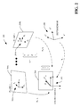
- FIG. 2 illustrates coordinate systems of the color camera and the depth sensor.
- FIG. 3 is a functional block diagram of an exemplary system that facilitates overlaying a color image onto a depth image based at least in part upon a computed rotation and translation between a color camera and a depth sensor.
- FIG. 4 is a flow diagram that illustrates an exemplary methodology for automatically jointly calibrating a color camera and a depth sensor.
- FIG. 5 is an exemplary computing system.
- the terms “component” and “system” are intended to encompass computer-readable data storage that is configured with computer-executable instructions that cause certain functionality to be performed when executed by a processor.
- the computer-executable instructions may include a routine, a function, or the like. It is also to be understood that a component or system may be localized on a single device or distributed across several devices.
- the system 100 comprises a receiver component 102 that receives a first digital image from a color camera 104 and a second digital image from a depth sensor 106 .
- the first digital image output by the color camera 104 may have a resolution that is the same as the resolution of the second digital image output by the depth sensor 106 .
- the depth sensor 106 may be or include any suitable type of depth sensor system including, but not limited to, a stereo vision or structured light system, a depth from focus system, a depth from shape system, a depth from motion system, a time of flight system, or the like.
- a clock 108 can be in communication with the color camera 104 and the depth sensor 106 , and can assign timestamps to images generated by the color camera 104 and the depth sensor 106 , such that images from the color camera 104 and depth sensor 106 that correspond to one another in time can be determined.
- a housing 110 may comprise the color camera 104 , the depth sensor 106 , and the clock 108 .
- the housing 110 may be a portion of a sensor that is utilized in connection with a video game console to detect position and motion of a game player.
- the housing 110 may be a portion of a computing system that includes the color camera 104 and the depth sensor 106 for purposes of video-based communications.
- the housing 110 may be for a video camera that is configured to generate three-dimensional video.
- the combination of the color camera 104 and the depth sensor 106 can be utilized in connection with a variety of different types of applications, including three-dimensional shape scanning, foreground-background segmentation, facial expression tracking, three-dimensional image or video generation, amongst others.
- the color camera 104 and the depth sensor 106 may be directed at a user 112 that is holding or supporting a planar object 114 .
- the planar object 114 may be a patterned object such as a game board.
- the planar object 114 may be a checkerboard.
- the user 112 can be instructed to move the planar object 114 to a plurality of different locations, and the color camera 104 and the depth sensor 106 can capture images that include the planar object 114 at these various locations.
- a calibrator component 116 is in communication with the receiver component 102 and jointly calibrates the color camera 104 and the depth sensor 106 based at least in part upon the first digital image generated by the color camera 104 and the second digital image generated by the depth sensor 106 .
- jointly calibrating the color camera 104 and the depth sensor 106 may comprise computing a rotation and translation between a coordinate system of the color camera 104 and a coordinate system of the depth sensor 106 .
- the calibrator component 116 can output values that indicate how the color camera 104 is aligned and rotated with respect to the depth sensor 106 .
- a data store 118 can be accessible to the calibrator component 116 , and the calibrator component 116 can cause the rotation and translation to be retained in the data store 118 .
- the data store 118 may be any suitable hardware data store, including a hard drive, memory, or the like.
- the calibrator component 116 may utilize any suitable technique for jointly calibrating the color camera 104 and the depth sensor 106 .
- the calibrator component 116 can have knowledge of the three-dimensional orientation and position of the planar object 114 in the first digital image generated by the color camera 104 based at least in part upon a priori knowledge of the pattern of the planar object 114 .
- the calibrator component 116 can leverage the knowledge of the existence of the planar object 114 in the second digital image generated by the depth sensor 106 to compute the rotation and translation between the coordinate systems of the color camera 104 and the depth sensor 106 , respectively. Specifically, the calibrator component 116 can fit a plane that corresponds to the planar object 114 in the image generated by the color camera 104 onto the second digital image generated by the depth sensor 106 . Such plane can be fit based at least in part upon three-dimensional points in the second digital image generated by the depth sensor 106 .
- the plane fit onto the image generated by the depth sensor 106 and the plane corresponding to the planar object 114 observed in the first digital image generated by the color camera 104 correspond to one another by the rotation and translation that is desirably computed.
- the calibrator component 116 can compute such rotation and translation and cause these values to be retained in the data store 118 .
- the calibrator component 116 can randomly sample points in the second digital image generated by the depth sensor 106 that are known to correspond to the planar object 114 in the second digital image. Each randomly sampled point in the image generated by the depth sensor 106 will correspond to a point in the color image that corresponds to the planar object 114 . Each point in the image generated by the depth sensor 106 that corresponds to the planar object 114 is related to a point in the image generated by the color camera 104 that corresponds to the planar object 114 by the desirably computed rotation and translation values. If a sufficient number of points are sampled, the calibrator component 116 can compute the values for rotation and translation. Still further, a combination of these approaches can be employed.
- the calibrator component 116 can consider multiple image pairs with the planar object 114 placed at various different locations and orientations relative to the color camera 104 and the depth sensor 106 .
- a minimum number of image pairs used by the calibrator component 116 to determine a rotation matrix can be 2
- a minimum number of image pairs used by the calibrator component 116 to determine a translation can be 3.
- the rotation and translation between the color camera 104 and the depth sensor 106 may then be computed based upon correspondence of the planar object 114 across various color image/depth image pairs.
- calibrator component 116 has been described above as jointly calibrating the color camera 104 and the depth sensor 106 through analysis of images generated thereby that include the planar object 114 , in other exemplary embodiments an object captured in the images need not be entirely planar.
- a planar board that includes a plurality of apertures in a pattern can be utilized such that the pattern can be recognized in the first digital image generated by the color camera 104 and the pattern can also be recognized in the second digital image generated by the depth sensor 106 .
- a correspondence between the located patterns in the first digital image and the second digital image may then be employed by the calibrator component 116 to compute the rotation and translation between respective coordinate systems of the color camera 104 and the depth sensor 106 .
- the calibrator component 116 can consider point correspondences between the first digital image generated by the color camera 104 and the second digital image generated by the depth sensor 106 in connection with jointly calibrating the color camera 104 and the depth sensor 106 . For instance, a user may manually indicate a point in the color image and a point in the depth image, wherein these two points correspond to one another across the images. Additionally or alternatively, image analysis techniques can be employed to automatically locate corresponding points across images generated by the color camera 104 and the depth sensor 106 . For instance, the calibrator component 116 can learn a likelihood function that minimizes projected distance between corresponding point pairs across images generated by the color camera 104 and images generated by the depth sensor 106 .
- the calibrator component 116 may consider distortion in the depth sensor 106 when jointly calibrating the color camera 104 with the depth sensor 106 .
- depth values generated by the depth sensor 106 may have some distortion associated therewith.
- a model of such distortion is contemplated and can be utilized by the calibrator component 116 when jointly calibrating the color camera 104 and the depth sensor 106 .
- a three-dimensional coordinate system 202 of the color camera 104 may coincide with a world coordinate system.
- A is the intrinsic matrix of the color camera 104 , which can be given as follows:
- A [ ⁇ ⁇ u 0 0 ⁇ v 0 0 0 1 ] ( 2 )
- ⁇ and ⁇ are the scale factors in the image coordinate system
- (u 0 , v 0 ) are the coordinates of the principal point
- ⁇ is the skewness of the two image axes.
- the depth sensor 106 has a second coordinate system 204 that is different from the coordinate system 202 of the color camera 104 .
- R and t The rotation and translation between the color camera 104 and the depth camera or depth sensor 106 is denoted by R and t:
- the planar object 114 can be moved in front of the color camera 104 and the depth sensor 106 . This can create n image pairs (color and depth) captured by the depth camera (the color camera 104 and the depth sensor 106 ). As shown, the position of the planar object 114 in the n images will be different.
- the model plane 204 thus has different positions and orientations relative to the position of the color camera 104 .
- the model plane 204 has a set of M feature points.
- the feature points can be corners of a known pattern in the planar object 114 , such as a checkerboard pattern.
- M i , j [ R i t i 0 T 1 ] ⁇ P j , ( 4 )
- M ij is the jth feature point of the ith image in the world coordinate system 202
- R i and t i are the rotation and translation from the ith model plane's local coordinate system 203 a to the world coordinate system 202 .
- the feature points are observed in the color image as m i,j , which are associated with M i,j through Eq. (1).
- the intrinsic matrix A the rotations and translations between the models planes 204 a and 204 b and the model plane 204 R i and t i , and the transform between the color camera 104 and the depth sensor 106 R and t.
- the intrinsic matrix A and the model plane positions R i and t i can be computed through conventional techniques. Images generated by the depth sensor 106 can be used to compute R and t automatically.
- feature points on images generated by the color camera 104 are typically extracted automatically through utilization of computer-executable algorithms, and therefore may have errors associated therewith. Accordingly, if it is assumed that M i,j follows a Gaussian distribution with the ground truth position as its mean, e.g., m ij ⁇ N ( m ij , ⁇ ij ), (6) then the log likelihood function can be written as follows:
- M ik i d can follow a Gaussian distribution as: m ik i d ⁇ N ( M ik i d , ⁇ ik i d ). (10)
- ⁇ ip i N( m ip i , ⁇ ip i ); M ip i d ⁇ N( M ip i d , ⁇ ip i d ), (16) where ⁇ ip i models the inaccuracy of the point in the image generated by the color camera 104 , and ⁇ ip i d models the uncertainty of the three-dimensional point in the image generated by the depth sensor 106 .
- the log likelihood function can then be written as follows:
- This objective function can be classified as a nonlinear least squares problem, which can be solved by the calibrator component 116 using the Levenberg-Marquardt method. The result is the computation of the parameters A, R i , t i R, t.
- the above algorithms describe calibration of the color camera 104 and the depth sensor 106 with an assumption of no distortions or noise in either of the color camera 104 or the depth sensor 106 .
- a few other parameters may be desirably estimated during calibration by the calibrator component 116 . These parameters can include focus, camera center, and depth mapping function for both the color camera 104 and the depth sensor 106 .
- the color camera 104 may exhibit lens distortions and thus it may be desirable to estimate such distortions based upon the observed model planes 204 a - 204 b in images generated by the color camera 104 .
- Another set of unknown parameters may be in a depth mapping function.
- an exemplary structured light-based depth camera may have a depth mapping function as follows:
- ⁇ and ⁇ are the scale and bias of the z value
- a d is the intrinsic matrix of the depth sensor 106 , which is typically predetermined.
- the other two parameters ⁇ and ⁇ can be used to model the calibration of the depth sensor 106 due to temperature variation or mechanical vibration, and can be estimated within the same maximum likelihood framework by the calibrator component 116 .
- the exemplary solution described above pertains to randomly sampling points in the image generated by the depth sensor 106 .
- the calibrator component 116 can use other approaches as alternatives to the techniques described above or in combination with such techniques. For instance, fitting the model plane 204 a - 204 b onto the corresponding image generated by the depth sensor 106 can be undertaken by the calibrator component 116 in connection with calibrating the color camera 104 with the depth sensor 106 . In an exemplary embodiment, this plane fitting can be undertaken during initialization to have a first estimate of unknown parameters. For instance, for the parameters related to the color camera 104 , e.g., A, R i , t i , a known initialization scheme can be adapted.
- n i d is the normal of the model plane in the three-dimensional coordinate system of the depth sensor 106
- ⁇ n i d ⁇ 2 1
- b i d is the bias from the origin.
- ⁇ n i d ⁇ and b i d can be found by the calibrator component 116 through least squares fitting.
- model plane In the coordinate system of the color camera 104 (the global coordinate system 202 ), the model plane can also be described by the following plane equation:
- R may first be solved.
- R can be denoted as follows:
- Another exemplary method that can be used by the calibrator component 116 to estimate the initial rotation R and translation t is through knowledge of a set of point correspondences between images generated by the color camera 104 and images generated by the depth sensor 106 .
- the following relationship exists: s ip i m ip i A[R t]M ip i d . (31)
- the intrinsic matrix A is known. In conventional methods, it has been shown that given three point pairs, there are in general four solutions to the rotation and translation. When one has four or more non-co-planar point pairs, the so-called POSIT algorithm can be used to find initial values of R and t.
- the system 300 comprises the data store 118 , which includes the computed rotation and translation matrices R and t.
- the system 300 further comprises a mapper component 302 that receives an image pair from the color camera 104 and the depth sensor 106 .
- the mapper component 302 can apply the R and t to the images received from the color camera 104 and/or the depth sensor 106 , thereby, for instance, overlaying the color image on the depth image to generate a three-dimensional image. Pursuant to an example, this can be undertaken to generate a three-dimensional video stream.
- an exemplary methodology 400 is illustrated and described. While the methodology is described as being a series of acts that are performed in a sequence, it is to be understood that the methodology is not limited by the order of the sequence. For instance, some acts may occur in a different order than what is described herein. In addition, an act may occur concurrently with another act. Furthermore, in some instances, not all acts may be required to implement the methodology described herein.
- the acts described herein may be computer-executable instructions that can be implemented by one or more processors and/or stored on a computer-readable medium or media.
- the computer-executable instructions may include a routine, a sub-routine, programs, a thread of execution, and/or the like.
- results of acts of the methodologies may be stored in a computer-readable medium, displayed on a display device, and/or the like.
- the computer-readable medium may be any suitable computer-readable storage device, such as memory, hard drive, CD, DVD, flash drive, or the like.
- the term “computer-readable medium” is not intended to encompass a propagated signal.
- the exemplary methodology 400 facilitates jointly calibrating a color camera and depth sensor is illustrated.
- the methodology 400 starts at 402 , and at 404 an image generated by a color camera that includes a planar object is received. Prior to receiving the image, an instruction can be output to a user with respect to placement of the planar object relative to the color camera and depth sensor.
- a depth image generated by a depth sensor is received, wherein the depth image additionally comprises the planar object.
- the image generated by the color camera and the image generated by the depth sensor may coincide with one another in time.
- the color camera and the depth sensor are automatically jointly calibrated based at least in part upon the image that comprises the planar object generated by the color camera and the depth image that comprises the planar object generated by the depth sensor.
- Exemplary techniques for automatically jointly calibrating the color camera in the depth sensor have been described above. Further, while the above has indicated that a single image pair is used, it is to be understood that several image pairs (color images and depth images) can be utilized to jointly calibrate the color camera and depth sensor.
- the methodology 400 completes at 410 .
- FIG. 5 a high-level illustration of an exemplary computing device 500 that can be used in accordance with the systems and methodologies disclosed herein is illustrated.
- the computing device 500 may be used in a system that supports jointly calibrating a color camera and a depth sensor in a depth camera.
- at least a portion of the computing device 500 may be used in a system that supports modeling noise/distortion of a color camera and/or depth sensor.
- the computing device 500 includes at least one processor 502 that executes instructions that are stored in a memory 504 .
- the memory 504 may be or include RAM, ROM, EEPROM, Flash memory, or other suitable memory.
- the instructions may be, for instance, instructions for implementing functionality described as being carried out by one or more components discussed above or instructions for implementing one or more of the methods described above.
- the processor 502 may access the memory 504 by way of a system bus 506 .
- the memory 504 may also store images (depth and/or color), computed rotation and translation values, etc.
- the computing device 500 additionally includes a data store 508 that is accessible by the processor 502 by way of the system bus 506 .
- the data store may be or include any suitable computer-readable storage, including a hard disk, memory, etc.
- the data store 508 may include executable instructions, images, etc.
- the computing device 500 also includes an input interface 510 that allows external devices to communicate with the computing device 500 .
- the input interface 510 may be used to receive instructions from an external computer device, from a user, etc.
- the computing device 500 also includes an output interface 512 that interfaces the computing device 500 with one or more external devices.
- the computing device 500 may display text, images, etc. by way of the output interface 512 .
- the computing device 500 may be a distributed system. Thus, for instance, several devices may be in communication by way of a network connection and may collectively perform tasks described as being performed by the computing device 500 .
Landscapes
- Engineering & Computer Science (AREA)
- Multimedia (AREA)
- Signal Processing (AREA)
- Computer Vision & Pattern Recognition (AREA)
- Physics & Mathematics (AREA)
- General Physics & Mathematics (AREA)
- Theoretical Computer Science (AREA)
- Length Measuring Devices By Optical Means (AREA)
- Image Processing (AREA)
- Measurement Of Optical Distance (AREA)
Abstract
Description
sm=A[I 0]M (1)
where I is the identity matrix, 0 is the zero vector, and s can be a scale factor. In an exemplary embodiment, s=Z. A is the intrinsic matrix of the
where α and β are the scale factors in the image coordinate system, (u0, v0) are the coordinates of the principal point and γ is the skewness of the two image axes.
where Mij is the jth feature point of the ith image in the world coordinate
sijmij=A[Ri,ti]Pj. (5)
In practice, feature points on images generated by the
m ij ˜N(
then the log likelihood function can be written as follows:
which indicates that if these points are transformed to the local coordinate system of each
m ik
sip
Further, whether the point correspondences are manually labeled or automatically established, such point correspondences may not be accurate. According, the following can be assumed:
mip
where Φip
Combining the above information together, the overall log likelihood can be maximized as follows:
maxA,R
where ρi, i=1,2,3 are weighting parameters. This objective function can be classified as a nonlinear least squares problem, which can be solved by the
where μ and υ are the scale and bias of the z value, and Ad is the intrinsic matrix of the
where ni d is the normal of the model plane in the three-dimensional coordinate system of the
Since Ri and ti are known, the plane's normal can be represented as ni, ∥ni∥2=1, and bias from the origin bi.
The following objective function may then be minimized with constraint:
J(R)=Σi=1 n ∥n i −Rn i d∥+Σj=1 3λj(r j T r j−1)+2λ4 r 1 T r 2+2λ5 r 1 T r 3+2λ6r2Tr3. (26)
Such objective function can be solved in closed form as follows:
C=Σi=1 nni dni T (27)
The singular value decomposition of C can be written as:
C=UDVT, (28)
where U and V are orthogonal matrices and D is a diagonal matrix. The rotation matrix is as follows:
R=VUT. (29)
The minimum number of images to determine the rotation matrix R is n=2, provided that the two model planes are not parallel to one another.
(n i d)T t+b i d =b i. (30)
Accordingly, three non-parallel model planes can determine a unique t. If n>3, t may be solved through least squares fitting.
sip
It can be noted that the intrinsic matrix A is known. In conventional methods, it has been shown that given three point pairs, there are in general four solutions to the rotation and translation. When one has four or more non-co-planar point pairs, the so-called POSIT algorithm can be used to find initial values of R and t.
Claims (20)
Priority Applications (2)
| Application Number | Priority Date | Filing Date | Title |
|---|---|---|---|
| US13/178,494 US9270974B2 (en) | 2011-07-08 | 2011-07-08 | Calibration between depth and color sensors for depth cameras |
| PCT/US2012/045879 WO2013009662A2 (en) | 2011-07-08 | 2012-07-08 | Calibration between depth and color sensors for depth cameras |
Applications Claiming Priority (1)
| Application Number | Priority Date | Filing Date | Title |
|---|---|---|---|
| US13/178,494 US9270974B2 (en) | 2011-07-08 | 2011-07-08 | Calibration between depth and color sensors for depth cameras |
Publications (2)
| Publication Number | Publication Date |
|---|---|
| US20130010079A1 US20130010079A1 (en) | 2013-01-10 |
| US9270974B2 true US9270974B2 (en) | 2016-02-23 |
Family
ID=47438425
Family Applications (1)
| Application Number | Title | Priority Date | Filing Date |
|---|---|---|---|
| US13/178,494 Active 2032-08-15 US9270974B2 (en) | 2011-07-08 | 2011-07-08 | Calibration between depth and color sensors for depth cameras |
Country Status (2)
| Country | Link |
|---|---|
| US (1) | US9270974B2 (en) |
| WO (1) | WO2013009662A2 (en) |
Cited By (11)
| Publication number | Priority date | Publication date | Assignee | Title |
|---|---|---|---|---|
| US20160073080A1 (en) * | 2014-09-05 | 2016-03-10 | Qualcomm Incorporated | Method and apparatus for efficient depth image transformation |
| US10712529B2 (en) | 2013-03-13 | 2020-07-14 | Cognex Corporation | Lens assembly with integrated feedback loop for focus adjustment |
| US11002854B2 (en) | 2013-03-13 | 2021-05-11 | Cognex Corporation | Lens assembly with integrated feedback loop and time-of-flight sensor |
| US11423572B2 (en) * | 2018-12-12 | 2022-08-23 | Analog Devices, Inc. | Built-in calibration of time-of-flight depth imaging systems |
| EP4250751A1 (en) * | 2022-03-24 | 2023-09-27 | Beijing Xiaomi Mobile Software Co., Ltd. | Depth camera, device for collecting depth image, muilti-sensor fusion system and autonomous mobile device |
| EP4250724A1 (en) * | 2022-03-24 | 2023-09-27 | Beijing Xiaomi Mobile Software Co., Ltd. | Multi-sensor fusion system and autonomous mobile apparatus |
| US20240197151A1 (en) * | 2019-08-16 | 2024-06-20 | Intuitive Surgical Operations, Inc. | Medical imaging systems and methods |
| US12307690B2 (en) | 2021-08-19 | 2025-05-20 | Industrial Technology Research Institute | Multi-modal image alignment method and system |
| KR20250084544A (en) | 2023-12-04 | 2025-06-11 | 한국과학기술원 | Internal Stray Light Estimation System and Method for Coaxial Scanning LiDAR, and Calibration System for LiDAR Using The Same |
| US12422919B2 (en) | 2023-11-09 | 2025-09-23 | Electronics And Telecommunications Research Institute | System and method for providing virtual reality service |
| US12579597B2 (en) * | 2022-07-20 | 2026-03-17 | Daihen Corporation | Point group data synthesis apparatus, non-transitory computer-readable medium having recorded thereon point group data synthesis program, point group data synthesis method, and point group data synthesis system |
Families Citing this family (40)
| Publication number | Priority date | Publication date | Assignee | Title |
|---|---|---|---|---|
| EP2334089A1 (en) * | 2009-12-04 | 2011-06-15 | Alcatel Lucent | A method and systems for obtaining an improved stereo image of an object |
| US9384585B2 (en) * | 2012-10-23 | 2016-07-05 | Electronics And Telecommunications Research Institute | 3-dimensional shape reconstruction device using depth image and color image and the method |
| KR101428866B1 (en) * | 2012-10-26 | 2014-08-12 | 한국과학기술원 | Apparatus and method for depth manipulation of streoscopic 3d |
| US9519968B2 (en) * | 2012-12-13 | 2016-12-13 | Hewlett-Packard Development Company, L.P. | Calibrating visual sensors using homography operators |
| US20140300702A1 (en) * | 2013-03-15 | 2014-10-09 | Tagir Saydkhuzhin | Systems and Methods for 3D Photorealistic Automated Modeling |
| US20140267617A1 (en) * | 2013-03-15 | 2014-09-18 | Scott A. Krig | Adaptive depth sensing |
| WO2014145279A1 (en) | 2013-03-15 | 2014-09-18 | Leap Motion, Inc. | Determining the relative locations of multiple motion-tracking devices |
| DE112013007165A5 (en) * | 2013-06-13 | 2016-03-10 | Leica Camera Ag | Camera with opto-electronic rangefinder |
| US10307912B2 (en) * | 2013-07-15 | 2019-06-04 | Lg Electronics Inc. | Robot cleaner and method for auto-correcting 3D sensor of the robot cleaner |
| US8917327B1 (en) | 2013-10-04 | 2014-12-23 | icClarity, Inc. | Method to use array sensors to measure multiple types of data at full resolution of the sensor |
| US9747680B2 (en) * | 2013-11-27 | 2017-08-29 | Industrial Technology Research Institute | Inspection apparatus, method, and computer program product for machine vision inspection |
| CN104677911B (en) * | 2013-11-27 | 2017-10-03 | 财团法人工业技术研究院 | Inspection apparatus and method for machine vision inspection |
| CN106255938B (en) | 2014-02-28 | 2019-12-17 | 惠普发展公司,有限责任合伙企业 | Calibration of sensors and projectors |
| KR102085228B1 (en) * | 2014-03-27 | 2020-03-05 | 한국전자통신연구원 | Imaging processing method and apparatus for calibrating depth of depth sensor |
| GB201407270D0 (en) * | 2014-04-24 | 2014-06-11 | Cathx Res Ltd | 3D data in underwater surveys |
| US11290704B2 (en) | 2014-07-31 | 2022-03-29 | Hewlett-Packard Development Company, L.P. | Three dimensional scanning system and framework |
| JP2016038889A (en) | 2014-08-08 | 2016-03-22 | リープ モーション, インコーポレーテッドLeap Motion, Inc. | Extended reality followed by motion sensing |
| US10033992B1 (en) * | 2014-09-09 | 2018-07-24 | Google Llc | Generating a 3D video of an event using crowd sourced data |
| PL3194882T3 (en) * | 2014-09-15 | 2021-10-25 | Dti Group Limited | Arcing filtering using multiple image capture devices |
| US20160360185A1 (en) * | 2015-06-03 | 2016-12-08 | Empire Technology Development Llc | Three-dimensional imaging sensor calibration |
| US9609242B2 (en) * | 2015-06-25 | 2017-03-28 | Intel Corporation | Auto-correction of depth-sensing camera data for planar target surfaces |
| US10129530B2 (en) * | 2015-09-25 | 2018-11-13 | Intel Corporation | Video feature tagging |
| US10003783B2 (en) * | 2016-02-26 | 2018-06-19 | Infineon Technologies Ag | Apparatus for generating a three-dimensional color image and a method for producing a three-dimensional color image |
| US20170270654A1 (en) * | 2016-03-18 | 2017-09-21 | Intel Corporation | Camera calibration using depth data |
| CN106296789B (en) * | 2016-08-05 | 2019-08-06 | 深圳迪乐普数码科技有限公司 | It is a kind of to be virtually implanted the method and terminal that object shuttles in outdoor scene |
| US11288834B2 (en) | 2017-05-23 | 2022-03-29 | Brainlab Ag | Determining the relative position between a point cloud generating camera and another camera |
| KR101979276B1 (en) * | 2017-08-09 | 2019-05-16 | 엘지전자 주식회사 | User interface apparatus for vehicle and Vehicle |
| CN109754427A (en) * | 2017-11-01 | 2019-05-14 | 虹软科技股份有限公司 | A kind of method and apparatus for calibration |
| CN108961344A (en) * | 2018-09-20 | 2018-12-07 | 鎏玥(上海)科技有限公司 | A kind of depth camera and customized plane calibration equipment |
| CN118033607A (en) * | 2018-12-12 | 2024-05-14 | 美国亚德诺半导体公司 | Built-in calibration of time-of-flight depth imaging systems |
| KR102690408B1 (en) | 2019-01-11 | 2024-07-30 | 엘지전자 주식회사 | Camera device, and electronic apparatus including the same |
| CN110312056B (en) * | 2019-06-10 | 2021-09-14 | 青岛小鸟看看科技有限公司 | Synchronous exposure method and image acquisition equipment |
| CN113465252B (en) * | 2020-05-29 | 2022-06-21 | 海信集团有限公司 | Intelligent refrigerator and drawer state detection method in intelligent refrigerator |
| WO2022051516A1 (en) | 2020-09-03 | 2022-03-10 | Cyberdontics (Usa), Inc. | Method and apparatus for cna analysis of tooth anatomy |
| CN112261303B (en) * | 2020-11-19 | 2021-08-20 | 贝壳技术有限公司 | Three-dimensional color panoramic model generation device and method, storage medium and processor |
| EP4314701A4 (en) * | 2021-03-30 | 2025-02-26 | Perceptive Technologies, Inc. | OPTICAL COHERENCE TOMOGRAPHY FOR INTRAORAL SCANNING |
| CN112738497A (en) * | 2021-03-30 | 2021-04-30 | 北京芯海视界三维科技有限公司 | Sensing device, image sensor and human-computer interaction system |
| CN120379583A (en) | 2022-09-08 | 2025-07-25 | 洞察科技公司 | Optical coherence tomography system and method |
| US20240221199A1 (en) * | 2022-12-30 | 2024-07-04 | Konica Minolta Business Solutions U.S.A., Inc. | Method and system for measuring planar features in 3d space using a combination of a 2d camera and a depth sensor |
| US12418635B2 (en) * | 2023-12-05 | 2025-09-16 | Zebra Technologies Corporation | Motion-based frame synchronization |
Citations (22)
| Publication number | Priority date | Publication date | Assignee | Title |
|---|---|---|---|---|
| US6373518B1 (en) * | 1998-05-14 | 2002-04-16 | Fuji Jukogyo Kabushiki Kaisha | Image correction apparatus for stereo camera |
| US6633664B1 (en) | 1999-05-11 | 2003-10-14 | Nippon Telegraph And Telephone Corporation | Three-dimensional structure acquisition method, apparatus and computer readable medium |
| US6768509B1 (en) | 2000-06-12 | 2004-07-27 | Intel Corporation | Method and apparatus for determining points of interest on an image of a camera calibration object |
| US6816187B1 (en) | 1999-06-08 | 2004-11-09 | Sony Corporation | Camera calibration apparatus and method, image processing apparatus and method, program providing medium, and camera |
| US6858826B2 (en) | 1996-10-25 | 2005-02-22 | Waveworx Inc. | Method and apparatus for scanning three-dimensional objects |
| US20050231476A1 (en) * | 1996-07-05 | 2005-10-20 | Armstrong Brad A | Image controller |
| US20060128087A1 (en) * | 2000-11-09 | 2006-06-15 | Canesta, Inc. | Methods and devices for improved charge management for three-dimensional and color sensing |
| US20070115484A1 (en) | 2005-10-24 | 2007-05-24 | Peisen Huang | 3d shape measurement system and method including fast three-step phase shifting, error compensation and calibration |
| US20090201384A1 (en) | 2008-02-13 | 2009-08-13 | Samsung Electronics Co., Ltd. | Method and apparatus for matching color image and depth image |
| US20090213240A1 (en) | 2008-02-25 | 2009-08-27 | Samsung Electronics Co., Ltd. | Method and apparatus for processing three-dimensional (3D) images |
| US20090231425A1 (en) | 2008-03-17 | 2009-09-17 | Sony Computer Entertainment America | Controller with an integrated camera and methods for interfacing with an interactive application |
| US20100207938A1 (en) | 2009-02-18 | 2010-08-19 | International Press Of Boston, Inc. | Simultaneous three-dimensional geometry and color texture acquisition using single color camera |
| US20100225743A1 (en) | 2009-03-05 | 2010-09-09 | Microsoft Corporation | Three-Dimensional (3D) Imaging Based on MotionParallax |
| US20100235129A1 (en) * | 2009-03-10 | 2010-09-16 | Honeywell International Inc. | Calibration of multi-sensor system |
| US20100303341A1 (en) * | 2009-06-01 | 2010-12-02 | Haeusler Gerd | Method and device for three-dimensional surface detection with a dynamic reference frame |
| US20110018973A1 (en) * | 2008-03-26 | 2011-01-27 | Konica Minolta Holdings, Inc. | Three-dimensional imaging device and method for calibrating three-dimensional imaging device |
| US20110054295A1 (en) * | 2009-08-25 | 2011-03-03 | Fujifilm Corporation | Medical image diagnostic apparatus and method using a liver function angiographic image, and computer readable recording medium on which is recorded a program therefor |
| US7912252B2 (en) | 2009-02-06 | 2011-03-22 | Robert Bosch Gmbh | Time-of-flight sensor-assisted iris capture system and method |
| US20110069892A1 (en) | 2009-09-24 | 2011-03-24 | Chih-Hsiang Tsai | Method of comparing similarity of 3d visual objects |
| US20110150101A1 (en) * | 2008-09-02 | 2011-06-23 | Yuan Liu | 3d video communication method, sending device and system, image reconstruction method and system |
| US8090194B2 (en) * | 2006-11-21 | 2012-01-03 | Mantis Vision Ltd. | 3D geometric modeling and motion capture using both single and dual imaging |
| US20120026296A1 (en) * | 2010-07-29 | 2012-02-02 | Samsung Electronics Co., Ltd. | Image processing apparatus and method |
-
2011
- 2011-07-08 US US13/178,494 patent/US9270974B2/en active Active
-
2012
- 2012-07-08 WO PCT/US2012/045879 patent/WO2013009662A2/en not_active Ceased
Patent Citations (22)
| Publication number | Priority date | Publication date | Assignee | Title |
|---|---|---|---|---|
| US20050231476A1 (en) * | 1996-07-05 | 2005-10-20 | Armstrong Brad A | Image controller |
| US6858826B2 (en) | 1996-10-25 | 2005-02-22 | Waveworx Inc. | Method and apparatus for scanning three-dimensional objects |
| US6373518B1 (en) * | 1998-05-14 | 2002-04-16 | Fuji Jukogyo Kabushiki Kaisha | Image correction apparatus for stereo camera |
| US6633664B1 (en) | 1999-05-11 | 2003-10-14 | Nippon Telegraph And Telephone Corporation | Three-dimensional structure acquisition method, apparatus and computer readable medium |
| US6816187B1 (en) | 1999-06-08 | 2004-11-09 | Sony Corporation | Camera calibration apparatus and method, image processing apparatus and method, program providing medium, and camera |
| US6768509B1 (en) | 2000-06-12 | 2004-07-27 | Intel Corporation | Method and apparatus for determining points of interest on an image of a camera calibration object |
| US20060128087A1 (en) * | 2000-11-09 | 2006-06-15 | Canesta, Inc. | Methods and devices for improved charge management for three-dimensional and color sensing |
| US20070115484A1 (en) | 2005-10-24 | 2007-05-24 | Peisen Huang | 3d shape measurement system and method including fast three-step phase shifting, error compensation and calibration |
| US8090194B2 (en) * | 2006-11-21 | 2012-01-03 | Mantis Vision Ltd. | 3D geometric modeling and motion capture using both single and dual imaging |
| US20090201384A1 (en) | 2008-02-13 | 2009-08-13 | Samsung Electronics Co., Ltd. | Method and apparatus for matching color image and depth image |
| US20090213240A1 (en) | 2008-02-25 | 2009-08-27 | Samsung Electronics Co., Ltd. | Method and apparatus for processing three-dimensional (3D) images |
| US20090231425A1 (en) | 2008-03-17 | 2009-09-17 | Sony Computer Entertainment America | Controller with an integrated camera and methods for interfacing with an interactive application |
| US20110018973A1 (en) * | 2008-03-26 | 2011-01-27 | Konica Minolta Holdings, Inc. | Three-dimensional imaging device and method for calibrating three-dimensional imaging device |
| US20110150101A1 (en) * | 2008-09-02 | 2011-06-23 | Yuan Liu | 3d video communication method, sending device and system, image reconstruction method and system |
| US7912252B2 (en) | 2009-02-06 | 2011-03-22 | Robert Bosch Gmbh | Time-of-flight sensor-assisted iris capture system and method |
| US20100207938A1 (en) | 2009-02-18 | 2010-08-19 | International Press Of Boston, Inc. | Simultaneous three-dimensional geometry and color texture acquisition using single color camera |
| US20100225743A1 (en) | 2009-03-05 | 2010-09-09 | Microsoft Corporation | Three-Dimensional (3D) Imaging Based on MotionParallax |
| US20100235129A1 (en) * | 2009-03-10 | 2010-09-16 | Honeywell International Inc. | Calibration of multi-sensor system |
| US20100303341A1 (en) * | 2009-06-01 | 2010-12-02 | Haeusler Gerd | Method and device for three-dimensional surface detection with a dynamic reference frame |
| US20110054295A1 (en) * | 2009-08-25 | 2011-03-03 | Fujifilm Corporation | Medical image diagnostic apparatus and method using a liver function angiographic image, and computer readable recording medium on which is recorded a program therefor |
| US20110069892A1 (en) | 2009-09-24 | 2011-03-24 | Chih-Hsiang Tsai | Method of comparing similarity of 3d visual objects |
| US20120026296A1 (en) * | 2010-07-29 | 2012-02-02 | Samsung Electronics Co., Ltd. | Image processing apparatus and method |
Non-Patent Citations (26)
| Title |
|---|
| "International Search Report", Mailed Date: Dec. 21, 2012, Application No. PCT/US2012/045879, Filed Date: Dec. 21, 2012, pp. 1-9. |
| Arun, et al., "Least-Squares Fitting of Two 3-D Point Sets", Retrieved at <<http://ieeexplore.ieee.org/stamp/stamp.jsp?tp=&arnumber=4767965>>, IEEE Transactions on Pattern Analysis and Machine Intelligenc, vol. PAMI-9, No. 5, Sep. 1987, pp. 698-700. |
| Arun, et al., "Least-Squares Fitting of Two 3-D Point Sets", Retrieved at >, IEEE Transactions on Pattern Analysis and Machine Intelligenc, vol. PAMI-9, No. 5, Sep. 1987, pp. 698-700. |
| C. Daniel Herrera, J. Kannala, & J. Heikkila, "Accurate and Practical Calibration of a Calibration of a Depth and Color Camera Pair", 6855 Lecture Notes in Computer Sci. 437-445 (Aug. 2011). * |
| C. Daniel Herrera, J. Kannala, & J. Heikkila, "Joint Depth and Color Camera Calibration with Distortion Correction", 34 IEEE Transactions on Patern Analysis & Machine Intelligence 2058-2064 (May 2012). * |
| C. Raposo, J.P. Barreto, & U. Nunes, Fast and Accurate Calibration of a Kinect Sensor, 2013 Int'l Conf. on 3D Vision 342-349 (2013). * |
| Cai, et al., "3D Deformable Face Tracking with a Commodity Depth Camera", Retrieved at <<http://research.microsoft.com/en-us/um/people/zhang/papers/eccv2010-facetrackingwithdepthcamera.pdf>>, Proceedings of the 11th European conference on computer vision: Part III, 2010, pp. 229-242. |
| Crabb, et al., "Real-Time Foreground Segmentation via Range and Color Imaging", Retrieved at <<http://mplab.ucsd.edu/wp-content/uploads/CVPR2008/WorkShops/data/papers/221.pdf>>, IEEE Computer Society Conference on Computer Vision and Pattern Recognition Workshops, Jun. 23-28, 2008, pp. 1-5. |
| Crabb, et al., "Real-Time Foreground Segmentation via Range and Color Imaging", Retrieved at >, IEEE Computer Society Conference on Computer Vision and Pattern Recognition Workshops, Jun. 23-28, 2008, pp. 1-5. |
| Cui, et al., "3D Shape Scanning with a Time-of-Flight Camera", Retrieved at <<http://ai.stanford.edu/˜schuon/sr/cvpr10-scanning.pdf>>, IEEE Conference on Computer Vision and Pattern Recognition, Jun. 13-18, 2010, pp. 1-8. |
| Cui, et al., "3D Shape Scanning with a Time-of-Flight Camera", Retrieved at >, IEEE Conference on Computer Vision and Pattern Recognition, Jun. 13-18, 2010, pp. 1-8. |
| Dementhon, et al., "Model-Based Object Pose in 25 Lines of Code", Retrieved at <<http://www.cfar.umd.edu/˜daniel/daniel-papersfordownload/Pose25Lines.ps.gz>>, Computer Vision-ECCV'95, 1995, pp. 1-30. |
| Dementhon, et al., "Model-Based Object Pose in 25 Lines of Code", Retrieved at >, Computer Vision-ECCV'95, 1995, pp. 1-30. |
| Fischler, et al., "Random Sample Consensus : A Paradigm for Model Fitting with Apphcatlons to Image Analysis and Automated Cartography", Retrieved at <<http://www.ai.sri.com/pubs/files/836.pdf>>, Communications of the ACM, vol. 24, No. 6, 1981, pp. 381-395. |
| Fischler, et al., "Random Sample Consensus : A Paradigm for Model Fitting with Apphcatlons to Image Analysis and Automated Cartography", Retrieved at >, Communications of the ACM, vol. 24, No. 6, 1981, pp. 381-395. |
| Frick, et al., "Generation of 3D-TV LDV-Content with Time of Flight Camera", Retrieved at <<http://citeseerx.ist.psu.edu/viewdoc/download?doi=10.1.1.155.5198&rep=rep1&type=pdf>>, 3DTV Conference: The True Vision-Capture, Transmission and Display of 3D Video, May 4-6, 2009, pp. 1-4. |
| Frick, et al., "Generation of 3D-TV LDV-Content with Time of Flight Camera", Retrieved at >, 3DTV Conference: The True Vision-Capture, Transmission and Display of 3D Video, May 4-6, 2009, pp. 1-4. |
| Guan, et al., "3D Object Reconstruction with Heterogeneous Sensor Data", Retrieved at <<http://www.cc.gatech.edu/conferences/3DPVT08/Program/Papers/paper108.pdf>>, The Fourth International Symposium on 3D Data Processing, Visualization and Transmission, 2008, pp. 1-8. |
| Guan, et al., "3D Object Reconstruction with Heterogeneous Sensor Data", Retrieved at >, The Fourth International Symposium on 3D Data Processing, Visualization and Transmission, 2008, pp. 1-8. |
| J. Smisek, J. Jancosek, & T. Pajdla, "3D with Kinect", 2011 IEEE Int'l conf. on Computer Vision Workshops 1154-1160 (Nov. 2011). * |
| Tsai, Roger Y., "A Versatile Camera Calibration Technique for High-Accuracy 3D Machine Vision Metrology using Off-the-Shelf TV Cameras and Lenses", Retrieved at <<http://www.vision.caltech.edu/bouguetj/calib-doc/papers/Tsai.pdf>>, IEEE Journal of Robotics and Automation, vol. 3, No. 4, Aug. 1987, pp. 323-344. |
| Tsai, Roger Y., "A Versatile Camera Calibration Technique for High-Accuracy 3D Machine Vision Metrology using Off-the-Shelf TV Cameras and Lenses", Retrieved at >, IEEE Journal of Robotics and Automation, vol. 3, No. 4, Aug. 1987, pp. 323-344. |
| Yuan, Joseph S. C., "A General Photogrammetric Method for Determining Object Position and Orientation", Retrieved at <<http://ieeexplore.ieee.org/stamp/stamp.jsp?tp=&arnumber=88034>>, IEEE Transactions on Robotics and Automation, vol. 5, No. 2, Apr. 1989, pp. 129-142. |
| Yuan, Joseph S. C., "A General Photogrammetric Method for Determining Object Position and Orientation", Retrieved at >, IEEE Transactions on Robotics and Automation, vol. 5, No. 2, Apr. 1989, pp. 129-142. |
| Zhang, et al., "A Flexible New Technique for Camera Calibration", Retrieved at <<http://ieeexplore.ieee.org/stamp/stamp.jsp?tp=&arnumber=888718>>, IEEE Transactions on Pattern Analysis and Machine Intelligence, vol. 22, No. 11, Nov. 2000, pp. 1330-1334. |
| Zhang, et al., "A Flexible New Technique for Camera Calibration", Retrieved at >, IEEE Transactions on Pattern Analysis and Machine Intelligence, vol. 22, No. 11, Nov. 2000, pp. 1330-1334. |
Cited By (17)
| Publication number | Priority date | Publication date | Assignee | Title |
|---|---|---|---|---|
| US11782156B2 (en) | 2013-03-13 | 2023-10-10 | Cognex Corporation | Lens assembly with integrated feedback loop and time-of-flight sensor |
| US10712529B2 (en) | 2013-03-13 | 2020-07-14 | Cognex Corporation | Lens assembly with integrated feedback loop for focus adjustment |
| US11002854B2 (en) | 2013-03-13 | 2021-05-11 | Cognex Corporation | Lens assembly with integrated feedback loop and time-of-flight sensor |
| US11422257B2 (en) | 2013-03-13 | 2022-08-23 | Cognex Corporation | Lens assembly with integrated feedback loop and time-of-flight sensor |
| US11513311B2 (en) | 2013-03-13 | 2022-11-29 | Cognex Corporation | Lens assembly with integrated feedback loop for focus adjustment |
| US9948911B2 (en) * | 2014-09-05 | 2018-04-17 | Qualcomm Incorporated | Method and apparatus for efficient depth image transformation |
| US20160073080A1 (en) * | 2014-09-05 | 2016-03-10 | Qualcomm Incorporated | Method and apparatus for efficient depth image transformation |
| US11423572B2 (en) * | 2018-12-12 | 2022-08-23 | Analog Devices, Inc. | Built-in calibration of time-of-flight depth imaging systems |
| US20240197151A1 (en) * | 2019-08-16 | 2024-06-20 | Intuitive Surgical Operations, Inc. | Medical imaging systems and methods |
| US12307690B2 (en) | 2021-08-19 | 2025-05-20 | Industrial Technology Research Institute | Multi-modal image alignment method and system |
| EP4250724A1 (en) * | 2022-03-24 | 2023-09-27 | Beijing Xiaomi Mobile Software Co., Ltd. | Multi-sensor fusion system and autonomous mobile apparatus |
| US12175733B2 (en) | 2022-03-24 | 2024-12-24 | Beijing Xiaomi Mobile Software Co., Ltd. | Depth camera assembly, device for collecting depth image and multi-sensor fusion system |
| EP4250751A1 (en) * | 2022-03-24 | 2023-09-27 | Beijing Xiaomi Mobile Software Co., Ltd. | Depth camera, device for collecting depth image, muilti-sensor fusion system and autonomous mobile device |
| US12367666B2 (en) | 2022-03-24 | 2025-07-22 | Beijing Xiaomi Mobile Software Co., Ltd. | Multi-sensor fusion system and autonomous mobile apparatus |
| US12579597B2 (en) * | 2022-07-20 | 2026-03-17 | Daihen Corporation | Point group data synthesis apparatus, non-transitory computer-readable medium having recorded thereon point group data synthesis program, point group data synthesis method, and point group data synthesis system |
| US12422919B2 (en) | 2023-11-09 | 2025-09-23 | Electronics And Telecommunications Research Institute | System and method for providing virtual reality service |
| KR20250084544A (en) | 2023-12-04 | 2025-06-11 | 한국과학기술원 | Internal Stray Light Estimation System and Method for Coaxial Scanning LiDAR, and Calibration System for LiDAR Using The Same |
Also Published As
| Publication number | Publication date |
|---|---|
| WO2013009662A2 (en) | 2013-01-17 |
| US20130010079A1 (en) | 2013-01-10 |
| WO2013009662A3 (en) | 2013-03-07 |
Similar Documents
| Publication | Publication Date | Title |
|---|---|---|
| US9270974B2 (en) | Calibration between depth and color sensors for depth cameras | |
| US11704833B2 (en) | Monocular vision tracking method, apparatus and non-transitory computer-readable storage medium | |
| US10916033B2 (en) | System and method for determining a camera pose | |
| CN102572505B (en) | System and method for calibrating a depth imaging sensor | |
| US9519968B2 (en) | Calibrating visual sensors using homography operators | |
| US9916689B2 (en) | Apparatus and method for estimating camera pose | |
| US11403781B2 (en) | Methods and systems for intra-capture camera calibration | |
| US10552984B2 (en) | Capture device calibration methods and systems | |
| Ramalingam et al. | Generic self-calibration of central cameras | |
| JP7657308B2 (en) | Method, apparatus and system for generating a three-dimensional model of a scene - Patents.com | |
| Olesen et al. | Real-time extraction of surface patches with associated uncertainties by means of kinect cameras | |
| EP4614443A1 (en) | Data processing method and apparatus, device, and storage medium | |
| EP3086285A1 (en) | Method of camera calibration for a multi-camera system and apparatus performing the same | |
| Schnieders et al. | Camera and light calibration from reflections on a sphere | |
| CN109214350A (en) | A kind of determination method, apparatus, equipment and the storage medium of illumination parameter | |
| CN117687506A (en) | VR scene multi-user interaction method, system, computer equipment and storage medium | |
| Ahmad et al. | An improved photometric stereo through distance estimation and light vector optimization from diffused maxima region | |
| Belter et al. | Modeling spatial uncertainty of point features in feature-based RGB-D SLAM | |
| Funk et al. | Using a raster display for photometric stereo | |
| Deldjoo et al. | A low-cost infrared-optical head tracking solution for virtual 3d audio environment using the nintendo wii-remote | |
| US11758100B2 (en) | Portable projection mapping device and projection mapping system | |
| Angelopoulou et al. | Evaluating the effect of diffuse light on photometric stereo reconstruction | |
| Francken et al. | Screen-camera calibration using a spherical mirror | |
| Audet et al. | Augmenting moving planar surfaces robustly with video projection and direct image alignment | |
| Paudel et al. | Localization of 2D cameras in a known environment using direct 2D-3D registration |
Legal Events
| Date | Code | Title | Description |
|---|---|---|---|
| AS | Assignment |
Owner name: MICROSOFT CORPORATION, WASHINGTON Free format text: ASSIGNMENT OF ASSIGNORS INTEREST;ASSIGNORS:ZHANG, CHA;ZHANG, ZHENGYOU;REEL/FRAME:026558/0949 Effective date: 20110706 |
|
| AS | Assignment |
Owner name: MICROSOFT TECHNOLOGY LICENSING, LLC, WASHINGTON Free format text: ASSIGNMENT OF ASSIGNORS INTEREST;ASSIGNOR:MICROSOFT CORPORATION;REEL/FRAME:034544/0001 Effective date: 20141014 |
|
| STCF | Information on status: patent grant |
Free format text: PATENTED CASE |
|
| MAFP | Maintenance fee payment |
Free format text: PAYMENT OF MAINTENANCE FEE, 4TH YEAR, LARGE ENTITY (ORIGINAL EVENT CODE: M1551); ENTITY STATUS OF PATENT OWNER: LARGE ENTITY Year of fee payment: 4 |
|
| MAFP | Maintenance fee payment |
Free format text: PAYMENT OF MAINTENANCE FEE, 8TH YEAR, LARGE ENTITY (ORIGINAL EVENT CODE: M1552); ENTITY STATUS OF PATENT OWNER: LARGE ENTITY Year of fee payment: 8 |