US9267298B2 - Tile alignment and leveling device - Google Patents

Tile alignment and leveling device Download PDF

Info

Publication number
US9267298B2
US9267298B2 US14/685,288 US201514685288A US9267298B2 US 9267298 B2 US9267298 B2 US 9267298B2 US 201514685288 A US201514685288 A US 201514685288A US 9267298 B2 US9267298 B2 US 9267298B2
Authority
US
United States
Prior art keywords
tiles
bottom plate
securing mechanism
flexible
component
Prior art date
Legal status (The legal status is an assumption and is not a legal conclusion. Google has not performed a legal analysis and makes no representation as to the accuracy of the status listed.)
Active
Application number
US14/685,288
Other versions
US20150211244A1 (en
Inventor
Edward A. Kufner
Ralph Burgin
Current Assignee (The listed assignees may be inaccurate. Google has not performed a legal analysis and makes no representation or warranty as to the accuracy of the list.)
Davinci Italia USA Group LLC
Original Assignee
Davinci Italia USA Group LLC
Priority date (The priority date is an assumption and is not a legal conclusion. Google has not performed a legal analysis and makes no representation as to the accuracy of the date listed.)
Filing date
Publication date
Application filed by Davinci Italia USA Group LLC filed Critical Davinci Italia USA Group LLC
Priority to US14/685,288 priority Critical patent/US9267298B2/en
Publication of US20150211244A1 publication Critical patent/US20150211244A1/en
Application granted granted Critical
Publication of US9267298B2 publication Critical patent/US9267298B2/en
Active legal-status Critical Current
Anticipated expiration legal-status Critical

Links

Images

Classifications

    • EFIXED CONSTRUCTIONS
    • E04BUILDING
    • E04FFINISHING WORK ON BUILDINGS, e.g. STAIRS, FLOORS
    • E04F21/00Implements for finishing work on buildings
    • E04F21/18Implements for finishing work on buildings for setting wall or ceiling slabs or plates
    • EFIXED CONSTRUCTIONS
    • E04BUILDING
    • E04FFINISHING WORK ON BUILDINGS, e.g. STAIRS, FLOORS
    • E04F21/00Implements for finishing work on buildings
    • E04F21/20Implements for finishing work on buildings for laying flooring
    • E04F21/22Implements for finishing work on buildings for laying flooring of single elements, e.g. flooring cramps ; flexible webs
    • EFIXED CONSTRUCTIONS
    • E04BUILDING
    • E04FFINISHING WORK ON BUILDINGS, e.g. STAIRS, FLOORS
    • E04F15/00Flooring
    • E04F15/02Flooring or floor layers composed of a number of similar elements
    • EFIXED CONSTRUCTIONS
    • E04BUILDING
    • E04FFINISHING WORK ON BUILDINGS, e.g. STAIRS, FLOORS
    • E04F21/00Implements for finishing work on buildings
    • EFIXED CONSTRUCTIONS
    • E04BUILDING
    • E04FFINISHING WORK ON BUILDINGS, e.g. STAIRS, FLOORS
    • E04F21/00Implements for finishing work on buildings
    • E04F21/0092Separate provisional spacers used between adjacent floor or wall tiles
    • EFIXED CONSTRUCTIONS
    • E04BUILDING
    • E04FFINISHING WORK ON BUILDINGS, e.g. STAIRS, FLOORS
    • E04F21/00Implements for finishing work on buildings
    • E04F21/18Implements for finishing work on buildings for setting wall or ceiling slabs or plates
    • E04F21/1838Implements for finishing work on buildings for setting wall or ceiling slabs or plates for setting a plurality of similar elements
    • E04F21/1877Leveling devices

Definitions

  • This invention is directed to the field of laying and leveling tile and slabs. More particularly, the invention is directed to a device for aligning and leveling adjacent tiles as they are laid in floors, walls, countertops, and the like.
  • Tile has become a popular decorative and functional article for use in floors, walls, countertops, and the like. Both professional tile installers and do-it-yourselfers spend a great deal of time aligning and leveling tiles as the tiles are being placed on a substrate's surface. Proper alignment and leveling of each tile is important for a number of reasons. One reason is that if one tile is improperly placed, the error will continue in adjacent tiles such that the installation will be unacceptable and the tiles will have to be replaced and/or ground and polished until the tiles are level or flat. In addition to aesthetic reasons for properly laying tile, a level surface is essential in tile floors so that people do not trip and fall on unevenly laid tiles. “Lippage” occurs when the edge of one tile is higher than the adjacent tile to a degree where someone could trip. Replacing or otherwise correcting errors in tile installation (such as lippage or improper tile alignment) takes time that adds to the total cost of the tile installation.
  • Laying and leveling tile can be difficult because many substrates are uneven, such as the ground when laying the for an outdoor patio. In this case, it can be difficult to raise the low areas of the substrate with mortar or other objects so that all the tiles are level. Further, tiles can shift and sink into mortar as the mortar dries. It has traditionally been necessary to continually monitor newly laid tiles as the mortar dries to ensure that the tiles remain level. Tile installers have used a variety of devices and methods to maintain quality tile installation while completing the installation process as fast as possible. One basic method uses markings on the substrate surface. Marking the installation surface requires the mortar to be carefully applied such that the marks remain visible. Although this technique aids in the alignment of the tiles, it does not keep the tiles level as they are laid in the mortar. Further, the use of this marking technique increases the amount of time required for the installation which results in increased cost.
  • Another device used for laying and leveling tile is a frame designed to space tiles an appropriate distance.
  • This type of frame is typically a fixed grid which is designed for a specific tile size.
  • One problem with this device is that it is a fixed size which requires a professional installer to carry multiple frames in order to install various tile sizes.
  • a further disadvantage of this type of frame is that it is only capable of installing one type of tile at a time.
  • Another device used to lay and align adjacent tiles is a spacer such as the one described in U.S. Pat. No. 6,625,951 (McCarthy). These types of spacers typically provide a square edge for properly aligning adjacent tiles at right angles, and a height adjustment means for adjusting the height of the tiles relative to the mortar surface.
  • One problem with these types of devices is that it is difficult to set multiple spacers to the same height which often results in an uneven tile surface.
  • a related problem with these types of devices is that the adjustment means does not allow the height of the tiles to be adjusted after the tile is laid because the height adjustment means is located under the tile.
  • the invention comprises a tile alignment and leveling device.
  • the device can be used to align and level tiles that are being secured to any suitable substrate, including floors, walls, and countertops.
  • the device includes at least one flexible member and a bottom plate combined by an intermediate member.
  • the device includes a bottom plate having a shaft extending upwardly therefrom and an intermediate member combined with at least one flexible member, said intermediate member having an opening adapted to receive the shaft.
  • the flexible members have a first end and a second end. The first end is pivotally combined with the intermediate member thereby allowing the flexible members to pivot between a first (upward) position and a second (downward) position.
  • the device includes a means for securing the flexible members in their second position.
  • a typical first step in laying tile is the application of a setting bed, such as a cement or mortar compound, to the substrate surface. Thereafter, the tiles can be placed in the setting bed.
  • the bottom plate is positioned in the setting bed beneath the tiles so that the intermediate member (or shaft in some embodiments) extends upward between adjacent tiles.
  • the bottom plate is preferably positioned so that it is in contact with more than one tile.
  • the flexible members are in their first position as the tiles are placed on the bottom plate. Thereafter, the flexible members are moved to their second position wherein the second end of the flexible members presses against the top of the tiles causing the top of the tiles to be aligned together on the same plane with minimal or no lippage.
  • the device keeps the tiles level relative to the adjacent tiles, not relative to the substrate surface.
  • the intermediate member (or shaft in some embodiments) is separated from the bottom plate leaving the bottom plate beneath the set tiles.
  • tile leveling devices can be simultaneously used between different tiles being laid on a substrate so as to level many tiles at the same time.
  • FIG. 1 is a perspective view of an embodiment of the invention
  • FIG. 2 is a front view of an embodiment of the invention
  • FIG. 3 is a perspective view of an embodiment of the invention.
  • FIG. 4 is a perspective view of an embodiment of the invention.
  • FIG. 5 is a perspective view of an alternate embodiment of the invention having an additional securing mechanism
  • FIG. 6 is a front view of the device being used with a tile
  • FIG. 7 is a side view of the device being used with two tiles
  • FIG. 8 is a front view of an alternate embodiment wherein the securing mechanism is a locking pawl system
  • FIG. 9 is a front view of the embodiment of FIG. 8 showing the flexible members in their locked position
  • FIG. 10 is a front view of an embodiment wherein the bottom plate has flexible members
  • FIG. 11 is a front view of an embodiment wherein the flexible members have a bend which allows for greater flexibility to accept different thickness of tile;
  • FIG. 12 is a perspective view showing an embodiment having an opening in the flexible members
  • FIG. 13 is a front view of the embodiment of FIG. 11 wherein one of the flexible members is in its second position;
  • FIG. 14 is a perspective view of an embodiment wherein the intermediate member slides along a shaft.
  • FIG. 15 is a front view of the embodiment shown in FIG. 14 wherein the device is being used with a tile.
  • the invention comprises a tile alignment and leveling device.
  • the device can be used to align and level tiles that are being secured to any suitable substrate, including floors, walls, and countertops.
  • the device includes at least one flexible member 10 and a bottom plate 12 .
  • the flexible members 10 and bottom plate 12 are combined by an intermediate member 18 which spaces the flexible members 10 and bottom plate 12 at a predetermined vertical distance.
  • the flexible members 10 have a first end 10 a , a second end 10 b , and a securing mechanism.
  • the first end 10 a is pivotally combined with the intermediate member 18 thereby allowing the flexible members 10 to pivot between a first position wherein the flexible members 10 are unsecured and allowed to pivot freely and a second position wherein the flexible members 10 are locked in their downward/engaged position.
  • the securing mechanism is used to secure the flexible members 10 in their second position.
  • the securing mechanism is a protruding fastening member 14 received by an opening 16 .
  • the protruding fastening member 14 is combined with the flexible member 10 and the opening 16 is in the intermediate member 18 . It should be noted, however, that the location of the securing mechanism components can be reversed. Any suitable securing mechanism may be used, including snaps, buttons, VELCRO, and quick set adhesives.
  • FIGS. 1-4 show an embodiment wherein each flexible member 10 has a single securing mechanism.
  • FIG. 5 shows an alternate embodiment wherein each flexible member 10 has more than one securing mechanism.
  • FIG. 5 shows a flexible member 10 having two fastening members 14 .
  • a first fastening member 14 a is positioned on one side of the intermediate member 18 and a second fastening member 14 b is positioned on a second side of the intermediate member 18 .
  • the fastening members 14 a , 14 b are received by one or more openings 16 in the intermediate member 18 .
  • FIGS. 8 and 9 show an alternate embodiment wherein the securing mechanism comprises a ratchet or locking pawl system.
  • This system is similar to a cable tie wherein a protruding locking tongue allows movement of the flexible member 10 in one direction but not in the opposite direction.
  • the locking pawl system has a shaft 40 with a plurality of teeth combined with the flexible members 10 and a locking pawl 42 is combined with the intermediate member 18 . It should be noted, however, that the location of the securing mechanism components can be reversed.
  • the locking pawl 42 interferes with the teeth to allow the flexible members 10 to move in a first direction (downward) but prevent the flexible members 10 from moving in the second (opposite) direction.
  • the locking pawl 42 comprises a release mechanism that may be manually activated by the user to release the interference between the pawl 42 and the teeth thereby allowing movement of the flexible members 10 in the second (upward) direction.
  • the teeth engage the locking pawl 42 so that it allows the flexible member 10 to be secured at multiple locking positions to accommodate a variety of thicknesses of tile 32 .
  • FIG. 11 shows an embodiment wherein the openings 16 in the intermediate member 18 are larger than the fastening members 14 .
  • the openings 16 are oval, however, they can be other suitable shapes includes slots, or circles.
  • the larger openings 16 allow the fastening members 14 to be secured in a number of different positions depending on the thickness of the tile 32 . In other words, for thicker tile 32 the fastening members 14 may rest farther to the top of the openings 16 and for thinner tile 32 the fastening members 14 may rest farther to the bottom of the openings 16 . This feature allows the device to be used with tile 32 having different thicknesses.
  • FIGS. 6 and 7 show the device being used with tile 32 .
  • a typical first step in laying tile 32 is the application of a setting bed 30 , such as a cement or mortar compound, to the substrate surface. Thereafter, the tiles 32 can be placed in the setting bed 30 .
  • the bottom plate 12 is positioned in the setting bed 30 beneath the tiles 32 so that the intermediate member 18 extends upward between adjacent tiles.
  • the bottom plate 12 is preferably positioned so that it is in contact with more than one tile 32 .
  • the flexible members 10 are in their first position as the tiles 32 are placed on the bottom plate 12 . Thereafter, the flexible members 10 are moved to their second position and secured by the securing mechanism.
  • the flexible members' second end 10 b presses against the top of the tiles 32 causing the top of the tiles 32 to be sandwiched between the flexible member second end 10 b and the bottom plate 12 .
  • the pressure between these two components aligns the edges of the tiles 32 in the same plane with minimal or no lippage.
  • the flexible members' second end 10 b is rounded. This rounded shape helps to reduce resistance between the flexible member second end 10 b and the tile 32 as the flexible members' second end 10 b passes over the top of the tile 32 while being moved to their second position. Any rounded shape including oval, cylinder, and semi-circle would also work to minimize resistance.
  • the flexible members 10 are comprised of a generally stiff material that has a slight flexible or spring-like quality, such as a plastic composite. As shown best in the embodiment of FIG. 2 , a portion of the flexible members 10 is curved.
  • the flexibility and curvature of the flexible members 10 allows the device to be used with tiles 32 of different thicknesses since the flexible members 10 can simply bend or flex for thicker tile 32 as they are moved to their second position and secured by the securing mechanism.
  • the flexible members 10 are moved from their first position to their second position then secured in their second position. In order to function properly, the tile 32 must be thicker than the distance D ( FIG.
  • FIGS. 11 and 13 show an embodiment wherein the flexible members 10 comprise a bend 10 c which helps them to flex even farther than the flexible members 10 shown in FIG. 2 to accept different thicknesses of tile.
  • portions of the intermediate portion 18 are also flexible. This can be seen in FIG. 13 wherein the horizontal portion of intermediate portion 18 flexes upward at its outer end when the flexible member 10 is in its second position.
  • FIG. 12 shows an embodiment having an opening 19 in the flexible members 10 . This opening 19 is adapted to receive a portion of the intermediate portion 18 as the flexible members 10 are moved from their first position to their second position. This helps with alignment thereby making it easier for the user to secure the securing mechanism in its proper position.
  • FIGS. 14 and 15 show an alternate embodiment wherein the bottom plate 12 has a shaft 15 extending upwardly therefrom and the intermediate member 18 has an opening adapted to receive the shaft.
  • the intermediate member 18 is prevented from moving upward along the shaft 15 by any suitable locking mechanism, including a locking pawl system (similar to the locking pawl system described above) wherein the locking mechanism allows the intermediate member 18 to move in a first direction along the shaft (toward the bottom plate 12 ) but prevents the intermediate member 18 from moving in a second (opposite) direction.
  • a locking pawl system similar to the locking pawl system described above
  • the flexible members 10 are then moved from their retracted position ( FIG. 14 ) to their compressed position ( FIG. 15 ) where they exert force against the tiles 32 .
  • the distance between the top of the intermediate member 18 (roughly point 10 a ) and the top of the tile 32 is shorter than the length of the flexible members 10 . This causes the flexible members 10 to bend as they are moved to their compressed position which in turn causes them to exert force against the tiles 32 as they try to return to their relaxed state.
  • the flexible members 10 remain in the compressed position until a user forces the flexible members 10 back to their retracted position.
  • the flexible members 10 remain in their compressed position without assistance from any securing mechanism since, in the compressed position, the second end 10 b of the flexible members 10 is pushed to a position where it is below or inside of (e.g. closer to the shaft 15 than) the first end 10 a of the flexible members 10 .
  • the flexible members 10 remain snapped or locked in their compressed position since the distance between the first end 10 a and the second end 10 b is longer than the distance between the first end 10 a and the tile 32 . In other words, the already compressed flexible members 10 would need to become even more compressed (bent) in order to move from their compressed position to their retracted position. This causes the flexible members 10 to become locked or snapped in their compressed position without assistance from any securing mechanism.
  • the bottom plate 12 preferably comprises one or more openings 28 .
  • the openings 28 allow the setting bed material to seep through the bottom plate 12 .
  • This seepage allows the setting bed material 30 to bond with the portion of the tile 32 directly above the bottom plate 12 , which otherwise may not contact much of the setting bed material 30 . Further, the seepage helps to ensure that the tiles 32 remain level as forces are applied to the plate 12 , setting bed material 30 , and/or tiles 32 during leveling and setting. If the setting bed material 30 was not allowed to seep through the bottom plate 12 , the setting bed material 30 could raise the bottom plate 12 as it dried which would consequently affect the level of the tiles 32 .
  • the user removes the portion of the device that is visible above the laid tiles 32 , i.e. the intermediate member 18 , the flexible members 10 , and the shaft 15 (in some embodiments).
  • the intermediate member 18 comprises a separation point 20 near the connection of the intermediate member 18 and the bottom plate 12 .
  • the separate point 20 is on the shaft 15 near its connection with the bottom plate 12 .
  • the separation point 20 is structurally weaker than the remainder of the intermediate member 18 (or shaft 15 ) so that the user can apply force to the portion of the intermediate member 18 (or shaft 15 ) that extends above the tiles 18 to cause the intermediate member 18 (or shaft 15 ) to break at its separation point 20 .
  • the separation point 20 comprises a single opening which allows the separation point 20 to be structurally weaker and separate when the proper force is applied by the user.
  • the separation point 20 comprises a plurality of micro holes or perforations which allow the separation point 20 to be structurally weaker and separate when the proper force is applied by the user.
  • FIGS. 1 the separation point 20 comprises a plurality of micro holes or perforations which allow the separation point 20 to be structurally weaker and separate when the proper force is applied by the user.
  • the separation point 20 includes an angled outer portion 21 wherein the intermediate member 18 tapers inward at each side. This angled outer portion 21 makes it easier for the user to separate the intermediate portion 18 from the bottom plate 12 .
  • the curing process of the setting bed pulls moisture out of the intermediate member 18 (or shaft 15 ) making it more brittle. This makes it easier for the user to break at the separation point 20 .
  • the bottom plate 12 remains below the tiles 32 and is therefore not reusable.
  • the intermediate member 18 (or shaft 15 ) is preferably made of a semi-rigid nylon which allows it to be more easily broken at its separation point 20 .
  • FIGS. 10 and 14 shows an embodiment wherein at least a portion of the bottom plate 12 is comprised of a material that has a flexible or spring-like quality similar to the types of materials that may be used for the flexible members 10 .
  • the flexible portion 50 of the bottom plate 12 is movable between a compressed position and a retracted position.
  • the flexible portion 50 of the bottom plate 12 is biased in its retracted position wherein the flexible portion 50 extends upward.
  • Weight from the tiles 32 or force applied from above causes the flexible portion 50 to move to its compressed position. In its compressed position, the flexible portion 50 exerts upward force on the tiles 32 as it tries to return to its retracted position.
  • the bottom plate 12 comprises two flexible portions 50 to allow the device to be used at the intersection of two tiles 32 and in other embodiments the bottom plate 12 comprises four flexible portions 50 to allow the device to be used at the intersection of four tiles 32 .
  • each flexible portion 50 begins near the center of the bottom plate 12 and extends upward and outward therefrom.
  • the flexible portion 50 begins near the outer ends of the bottom plate 12 and extends upward and inward.
  • the flexible portion 50 of the bottom plate 12 may be tapered so that it is thinner at its outer end to allow the device to be easily inserted under tiles 32 .
  • the flexible members 10 exert downward force against the top of the tiles 32 while the flexible portion 50 of the bottom plate 12 exerts upward force against the bottom of the tiles 32 .
  • the opposing forces work to help ensure the tiles 32 are firmly held between the flexible member 10 and bottom plate 12 to help ensure an even surface.
  • FIGS. 10 and 14 The embodiment shown in FIGS. 10 and 14 is also useful in situations where adjacent tiles 32 have different thicknesses.
  • the flexible portion 50 of the bottom plate 12 can be compressed under the weight of the thicker (heavier) tile 32 , while the flexible or spring-like quality of the bottom plate 12 can remain in its retracted position under the thinner (lighter) tile 32 thereby holding the two adjacent tiles 32 at the same elevation. In this manner, the tile alignment and leveling device is self-adjusting after it has been placed under the tiles 32 .

Abstract

A tile alignment and leveling device for aligning and leveling tiles as they are being secured to a substrate. The device includes a flexible member, a bottom plate, and an intermediate member. The intermediate member spaces the flexible member and bottom plate a predetermined vertical distance. The flexible member has a first end and a second end. The first end is pivotally combined with the intermediate member thereby allowing the flexible member to pivot between a first position and a second (downward) position. In use and in its second position, the flexible member second end exerts force against the top of the tiles to help align and level the tiles as they are secured to the substrate.

Description

This application is a continuation of U.S. patent application Ser. No. 13/853,523 filed Mar. 29, 2013 which is based upon U.S. Provisional Application Ser. No. 61/617,487 filed Mar. 29, 2012, the complete disclosures of which are hereby expressly incorporated by this reference.
BACKGROUND
This invention is directed to the field of laying and leveling tile and slabs. More particularly, the invention is directed to a device for aligning and leveling adjacent tiles as they are laid in floors, walls, countertops, and the like.
Tile has become a popular decorative and functional article for use in floors, walls, countertops, and the like. Both professional tile installers and do-it-yourselfers spend a great deal of time aligning and leveling tiles as the tiles are being placed on a substrate's surface. Proper alignment and leveling of each tile is important for a number of reasons. One reason is that if one tile is improperly placed, the error will continue in adjacent tiles such that the installation will be unacceptable and the tiles will have to be replaced and/or ground and polished until the tiles are level or flat. In addition to aesthetic reasons for properly laying tile, a level surface is essential in tile floors so that people do not trip and fall on unevenly laid tiles. “Lippage” occurs when the edge of one tile is higher than the adjacent tile to a degree where someone could trip. Replacing or otherwise correcting errors in tile installation (such as lippage or improper tile alignment) takes time that adds to the total cost of the tile installation.
Laying and leveling tile can be difficult because many substrates are uneven, such as the ground when laying the for an outdoor patio. In this case, it can be difficult to raise the low areas of the substrate with mortar or other objects so that all the tiles are level. Further, tiles can shift and sink into mortar as the mortar dries. It has traditionally been necessary to continually monitor newly laid tiles as the mortar dries to ensure that the tiles remain level. Tile installers have used a variety of devices and methods to maintain quality tile installation while completing the installation process as fast as possible. One basic method uses markings on the substrate surface. Marking the installation surface requires the mortar to be carefully applied such that the marks remain visible. Although this technique aids in the alignment of the tiles, it does not keep the tiles level as they are laid in the mortar. Further, the use of this marking technique increases the amount of time required for the installation which results in increased cost.
Another device used for laying and leveling tile is a frame designed to space tiles an appropriate distance. This type of frame is typically a fixed grid which is designed for a specific tile size. One problem with this device is that it is a fixed size which requires a professional installer to carry multiple frames in order to install various tile sizes. A further disadvantage of this type of frame is that it is only capable of installing one type of tile at a time.
Another device used to lay and align adjacent tiles is a spacer such as the one described in U.S. Pat. No. 6,625,951 (McCarthy). These types of spacers typically provide a square edge for properly aligning adjacent tiles at right angles, and a height adjustment means for adjusting the height of the tiles relative to the mortar surface. One problem with these types of devices is that it is difficult to set multiple spacers to the same height which often results in an uneven tile surface. A related problem with these types of devices is that the adjustment means does not allow the height of the tiles to be adjusted after the tile is laid because the height adjustment means is located under the tile.
Therefore, there is a need for an efficient and inexpensive tile leveling and alignment device that allows for the vertical alignment of tiles relative to each other after the tiles have been laid in the mortar.
SUMMARY
The invention comprises a tile alignment and leveling device. The device can be used to align and level tiles that are being secured to any suitable substrate, including floors, walls, and countertops. In some embodiments the device includes at least one flexible member and a bottom plate combined by an intermediate member. In other embodiments the device includes a bottom plate having a shaft extending upwardly therefrom and an intermediate member combined with at least one flexible member, said intermediate member having an opening adapted to receive the shaft. The flexible members have a first end and a second end. The first end is pivotally combined with the intermediate member thereby allowing the flexible members to pivot between a first (upward) position and a second (downward) position. In some embodiments the device includes a means for securing the flexible members in their second position.
A typical first step in laying tile is the application of a setting bed, such as a cement or mortar compound, to the substrate surface. Thereafter, the tiles can be placed in the setting bed. During these steps the bottom plate is positioned in the setting bed beneath the tiles so that the intermediate member (or shaft in some embodiments) extends upward between adjacent tiles. The bottom plate is preferably positioned so that it is in contact with more than one tile. The flexible members are in their first position as the tiles are placed on the bottom plate. Thereafter, the flexible members are moved to their second position wherein the second end of the flexible members presses against the top of the tiles causing the top of the tiles to be aligned together on the same plane with minimal or no lippage. The device keeps the tiles level relative to the adjacent tiles, not relative to the substrate surface.
After the setting bed dries, thereby securing the tiles to the substrate, the intermediate member (or shaft in some embodiments) is separated from the bottom plate leaving the bottom plate beneath the set tiles. One of ordinary skill in the art would understand that a plurality of tile leveling devices can be simultaneously used between different tiles being laid on a substrate so as to level many tiles at the same time.
BRIEF DESCRIPTION OF THE DRAWINGS
FIG. 1 is a perspective view of an embodiment of the invention;
FIG. 2 is a front view of an embodiment of the invention;
FIG. 3 is a perspective view of an embodiment of the invention;
FIG. 4 is a perspective view of an embodiment of the invention;
FIG. 5 is a perspective view of an alternate embodiment of the invention having an additional securing mechanism;
FIG. 6 is a front view of the device being used with a tile;
FIG. 7 is a side view of the device being used with two tiles;
FIG. 8 is a front view of an alternate embodiment wherein the securing mechanism is a locking pawl system;
FIG. 9 is a front view of the embodiment of FIG. 8 showing the flexible members in their locked position;
FIG. 10 is a front view of an embodiment wherein the bottom plate has flexible members;
FIG. 11 is a front view of an embodiment wherein the flexible members have a bend which allows for greater flexibility to accept different thickness of tile;
FIG. 12 is a perspective view showing an embodiment having an opening in the flexible members;
FIG. 13 is a front view of the embodiment of FIG. 11 wherein one of the flexible members is in its second position;
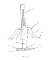
FIG. 14 is a perspective view of an embodiment wherein the intermediate member slides along a shaft; and
FIG. 15 is a front view of the embodiment shown in FIG. 14 wherein the device is being used with a tile.
DETAILED DESCRIPTION
The invention comprises a tile alignment and leveling device. The device can be used to align and level tiles that are being secured to any suitable substrate, including floors, walls, and countertops. The device includes at least one flexible member 10 and a bottom plate 12. In the embodiment shown in FIGS. 1-13, the flexible members 10 and bottom plate 12 are combined by an intermediate member 18 which spaces the flexible members 10 and bottom plate 12 at a predetermined vertical distance. The flexible members 10 have a first end 10 a, a second end 10 b, and a securing mechanism. The first end 10 a is pivotally combined with the intermediate member 18 thereby allowing the flexible members 10 to pivot between a first position wherein the flexible members 10 are unsecured and allowed to pivot freely and a second position wherein the flexible members 10 are locked in their downward/engaged position.
The securing mechanism is used to secure the flexible members 10 in their second position. In the embodiments shown in FIGS. 1-6, the securing mechanism is a protruding fastening member 14 received by an opening 16. In the embodiments shown in FIGS. 1-6, the protruding fastening member 14 is combined with the flexible member 10 and the opening 16 is in the intermediate member 18. It should be noted, however, that the location of the securing mechanism components can be reversed. Any suitable securing mechanism may be used, including snaps, buttons, VELCRO, and quick set adhesives.
FIGS. 1-4 show an embodiment wherein each flexible member 10 has a single securing mechanism. FIG. 5 shows an alternate embodiment wherein each flexible member 10 has more than one securing mechanism. FIG. 5 shows a flexible member 10 having two fastening members 14. A first fastening member 14 a is positioned on one side of the intermediate member 18 and a second fastening member 14 b is positioned on a second side of the intermediate member 18. The fastening members 14 a, 14 b are received by one or more openings 16 in the intermediate member 18.
FIGS. 8 and 9 show an alternate embodiment wherein the securing mechanism comprises a ratchet or locking pawl system. This system is similar to a cable tie wherein a protruding locking tongue allows movement of the flexible member 10 in one direction but not in the opposite direction. As shown, the locking pawl system has a shaft 40 with a plurality of teeth combined with the flexible members 10 and a locking pawl 42 is combined with the intermediate member 18. It should be noted, however, that the location of the securing mechanism components can be reversed. The locking pawl 42 interferes with the teeth to allow the flexible members 10 to move in a first direction (downward) but prevent the flexible members 10 from moving in the second (opposite) direction. In some embodiments the locking pawl 42 comprises a release mechanism that may be manually activated by the user to release the interference between the pawl 42 and the teeth thereby allowing movement of the flexible members 10 in the second (upward) direction. The teeth engage the locking pawl 42 so that it allows the flexible member 10 to be secured at multiple locking positions to accommodate a variety of thicknesses of tile 32.
FIG. 11 shows an embodiment wherein the openings 16 in the intermediate member 18 are larger than the fastening members 14. In the embodiment shown, the openings 16 are oval, however, they can be other suitable shapes includes slots, or circles. The larger openings 16 allow the fastening members 14 to be secured in a number of different positions depending on the thickness of the tile 32. In other words, for thicker tile 32 the fastening members 14 may rest farther to the top of the openings 16 and for thinner tile 32 the fastening members 14 may rest farther to the bottom of the openings 16. This feature allows the device to be used with tile 32 having different thicknesses.
FIGS. 6 and 7 show the device being used with tile 32. A typical first step in laying tile 32 is the application of a setting bed 30, such as a cement or mortar compound, to the substrate surface. Thereafter, the tiles 32 can be placed in the setting bed 30. During these steps the bottom plate 12 is positioned in the setting bed 30 beneath the tiles 32 so that the intermediate member 18 extends upward between adjacent tiles. The bottom plate 12 is preferably positioned so that it is in contact with more than one tile 32. The flexible members 10 are in their first position as the tiles 32 are placed on the bottom plate 12. Thereafter, the flexible members 10 are moved to their second position and secured by the securing mechanism. In the second position the flexible members' second end 10 b presses against the top of the tiles 32 causing the top of the tiles 32 to be sandwiched between the flexible member second end 10 b and the bottom plate 12. The pressure between these two components aligns the edges of the tiles 32 in the same plane with minimal or no lippage. In the embodiment shown in FIGS. 2 and 6, the flexible members' second end 10 b is rounded. This rounded shape helps to reduce resistance between the flexible member second end 10 b and the tile 32 as the flexible members' second end 10 b passes over the top of the tile 32 while being moved to their second position. Any rounded shape including oval, cylinder, and semi-circle would also work to minimize resistance.
In some embodiments the flexible members 10 are comprised of a generally stiff material that has a slight flexible or spring-like quality, such as a plastic composite. As shown best in the embodiment of FIG. 2, a portion of the flexible members 10 is curved. The flexibility and curvature of the flexible members 10 allows the device to be used with tiles 32 of different thicknesses since the flexible members 10 can simply bend or flex for thicker tile 32 as they are moved to their second position and secured by the securing mechanism. The flexible members 10 are moved from their first position to their second position then secured in their second position. In order to function properly, the tile 32 must be thicker than the distance D (FIG. 2) between the flexible member second end 10 b and the bottom plate 12 to allow the flexible member second end 10 b to exert force on the tile 32 when in its second position. FIGS. 11 and 13 show an embodiment wherein the flexible members 10 comprise a bend 10 c which helps them to flex even farther than the flexible members 10 shown in FIG. 2 to accept different thicknesses of tile. In some embodiments, portions of the intermediate portion 18 are also flexible. This can be seen in FIG. 13 wherein the horizontal portion of intermediate portion 18 flexes upward at its outer end when the flexible member 10 is in its second position. FIG. 12 shows an embodiment having an opening 19 in the flexible members 10. This opening 19 is adapted to receive a portion of the intermediate portion 18 as the flexible members 10 are moved from their first position to their second position. This helps with alignment thereby making it easier for the user to secure the securing mechanism in its proper position.
FIGS. 14 and 15 show an alternate embodiment wherein the bottom plate 12 has a shaft 15 extending upwardly therefrom and the intermediate member 18 has an opening adapted to receive the shaft. The intermediate member 18 is prevented from moving upward along the shaft 15 by any suitable locking mechanism, including a locking pawl system (similar to the locking pawl system described above) wherein the locking mechanism allows the intermediate member 18 to move in a first direction along the shaft (toward the bottom plate 12) but prevents the intermediate member 18 from moving in a second (opposite) direction. As shown in FIG. 15, once the tiles 32 are properly positioned and the bottom plate is placed beneath the tiles 32 as described above for the previous embodiments, the intermediate member 18 is moved down the shaft 15 toward the tiles 32. The flexible members 10 are then moved from their retracted position (FIG. 14) to their compressed position (FIG. 15) where they exert force against the tiles 32. The distance between the top of the intermediate member 18 (roughly point 10 a) and the top of the tile 32 is shorter than the length of the flexible members 10. This causes the flexible members 10 to bend as they are moved to their compressed position which in turn causes them to exert force against the tiles 32 as they try to return to their relaxed state. The flexible members 10 remain in the compressed position until a user forces the flexible members 10 back to their retracted position. The flexible members 10 remain in their compressed position without assistance from any securing mechanism since, in the compressed position, the second end 10 b of the flexible members 10 is pushed to a position where it is below or inside of (e.g. closer to the shaft 15 than) the first end 10 a of the flexible members 10. The flexible members 10 remain snapped or locked in their compressed position since the distance between the first end 10 a and the second end 10 b is longer than the distance between the first end 10 a and the tile 32. In other words, the already compressed flexible members 10 would need to become even more compressed (bent) in order to move from their compressed position to their retracted position. This causes the flexible members 10 to become locked or snapped in their compressed position without assistance from any securing mechanism.
It should be noted that the embodiment described in the preceding paragraph and shown in FIGS. 14 and 15 wherein the intermediate member 18 slides along a shaft 15 may use securing mechanisms (as described for other embodiments) to secure the flexible members 10 in their downward position instead of the locking engagement means described in the previous paragraph. Similarly, embodiments shown and described herein wherein the intermediate member 18 combines directly with the bottom plate 12 (with no shaft 15) which use securing mechanisms to retain the flexible members 10 in their downward position may instead use the locking engagement means described in the previous paragraph.
As seen best in FIG. 1, the bottom plate 12 preferably comprises one or more openings 28. The openings 28 allow the setting bed material to seep through the bottom plate 12. This seepage allows the setting bed material 30 to bond with the portion of the tile 32 directly above the bottom plate 12, which otherwise may not contact much of the setting bed material 30. Further, the seepage helps to ensure that the tiles 32 remain level as forces are applied to the plate 12, setting bed material 30, and/or tiles 32 during leveling and setting. If the setting bed material 30 was not allowed to seep through the bottom plate 12, the setting bed material 30 could raise the bottom plate 12 as it dried which would consequently affect the level of the tiles 32.
After the setting bed dries and the tiles 32 are secured to the substrate, the user removes the portion of the device that is visible above the laid tiles 32, i.e. the intermediate member 18, the flexible members 10, and the shaft 15 (in some embodiments). In the embodiment shown in FIGS. 1-13, the intermediate member 18 comprises a separation point 20 near the connection of the intermediate member 18 and the bottom plate 12. In the embodiment shown in FIGS. 14 and 15, the separate point 20 is on the shaft 15 near its connection with the bottom plate 12. The separation point 20 is structurally weaker than the remainder of the intermediate member 18 (or shaft 15) so that the user can apply force to the portion of the intermediate member 18 (or shaft 15) that extends above the tiles 18 to cause the intermediate member 18 (or shaft 15) to break at its separation point 20. In some embodiments, the separation point 20 comprises a single opening which allows the separation point 20 to be structurally weaker and separate when the proper force is applied by the user. In the embodiment shown in FIGS. 1 and 11, the separation point 20 comprises a plurality of micro holes or perforations which allow the separation point 20 to be structurally weaker and separate when the proper force is applied by the user. In the embodiment shown in FIGS. 1 and 2, the separation point 20 includes an angled outer portion 21 wherein the intermediate member 18 tapers inward at each side. This angled outer portion 21 makes it easier for the user to separate the intermediate portion 18 from the bottom plate 12. In one embodiment, the curing process of the setting bed pulls moisture out of the intermediate member 18 (or shaft 15) making it more brittle. This makes it easier for the user to break at the separation point 20. Once separated at the separation point 20, the bottom plate 12 remains below the tiles 32 and is therefore not reusable. The intermediate member 18 (or shaft 15) is preferably made of a semi-rigid nylon which allows it to be more easily broken at its separation point 20.
FIGS. 10 and 14 shows an embodiment wherein at least a portion of the bottom plate 12 is comprised of a material that has a flexible or spring-like quality similar to the types of materials that may be used for the flexible members 10. The flexible portion 50 of the bottom plate 12 is movable between a compressed position and a retracted position. The flexible portion 50 of the bottom plate 12 is biased in its retracted position wherein the flexible portion 50 extends upward. Weight from the tiles 32 or force applied from above causes the flexible portion 50 to move to its compressed position. In its compressed position, the flexible portion 50 exerts upward force on the tiles 32 as it tries to return to its retracted position. In some embodiments, the bottom plate 12 comprises two flexible portions 50 to allow the device to be used at the intersection of two tiles 32 and in other embodiments the bottom plate 12 comprises four flexible portions 50 to allow the device to be used at the intersection of four tiles 32. In the embodiment shown in FIGS. 10 and 14 each flexible portion 50 begins near the center of the bottom plate 12 and extends upward and outward therefrom. In other embodiments the flexible portion 50 begins near the outer ends of the bottom plate 12 and extends upward and inward. As shown in FIG. 10, the flexible portion 50 of the bottom plate 12 may be tapered so that it is thinner at its outer end to allow the device to be easily inserted under tiles 32.
In using the embodiment shown in FIGS. 10 and 14, after the flexible member 10 is secured in place, the flexible members 10 exert downward force against the top of the tiles 32 while the flexible portion 50 of the bottom plate 12 exerts upward force against the bottom of the tiles 32. The opposing forces work to help ensure the tiles 32 are firmly held between the flexible member 10 and bottom plate 12 to help ensure an even surface.
The embodiment shown in FIGS. 10 and 14 is also useful in situations where adjacent tiles 32 have different thicknesses. The flexible portion 50 of the bottom plate 12 can be compressed under the weight of the thicker (heavier) tile 32, while the flexible or spring-like quality of the bottom plate 12 can remain in its retracted position under the thinner (lighter) tile 32 thereby holding the two adjacent tiles 32 at the same elevation. In this manner, the tile alignment and leveling device is self-adjusting after it has been placed under the tiles 32.
Most existing tile leveling systems require tools, some of which are very expensive. One feature of this device is that absolutely no tools are necessary since the flexible members 10 can be made to exert force against the tiles 32 with only the user's hands. Not needing tools for the installation makes this device more affordable for the DIY market.
Having thus described the invention in connection with the preferred embodiments thereof, it will be evident to those skilled in the art that various revisions can be made to the preferred embodiments described herein with out departing from the spirit and scope of the invention. It is my intention, however, that all such revisions and modifications that are evident to those skilled in the art will be included with in the scope of the following claims.

Claims (15)

What is claimed is as follows:
1. A method for laying and leveling tiles, said method comprising:
providing a device having a bottom plate with a top side and a bottom side, a flexible member having a first end and a second end, and an intermediate member connecting the bottom plate to the flexible member;
placing the bottom plate beneath the tiles so that the intermediate member extends upward between adjacent tiles;
moving the flexible member from a first position to a second position where the second end engages the tiles; and
securing the flexible member in its second position using a securing mechanism having a first component combined with the flexible member and a second component combined with the intermediate member.
2. The method of claim 1 wherein the securing mechanism first component is a fastening member and the securing mechanism second component is an opening adapted to receive the fastening member.
3. The method of claim 1 wherein the securing mechanism second component is a fastening member and the securing mechanism first component is an opening adapted to receive the fastening member.
4. The method of claim 1 wherein the securing mechanism is a snap.
5. The method of claim 1 wherein the securing mechanism is a locking pawl system.
6. A method for laying and leveling tiles, said method comprising:
providing a device having a bottom plate with a top side and a bottom side, a flexible member having a first end and a second end, and an intermediate member connecting the bottom plate to the flexible member;
placing the bottom plate beneath the tiles so that the intermediate member extends upward between adjacent tiles;
moving the flexible member from a first position to a second position where the second end engages the tiles;
securing the flexible member in its second position using a securing mechanism having a first component combined with the flexible member and a second component combined with the intermediate member; and
separating the intermediate member from the bottom plate.
7. The method of claim 6 wherein the securing mechanism first component is a fastening member and the securing mechanism second component is an opening adapted to receive the fastening member.
8. The method of claim 6 wherein the securing mechanism second component is a fastening member and the securing mechanism first component is an opening adapted to receive the fastening member.
9. The method of claim 6 wherein the securing mechanism is a snap.
10. The method of claim 6 wherein the securing mechanism is a locking pawl system.
11. A method for laying and leveling tiles, said method comprising:
providing a device having a bottom plate with a top side and a bottom side, a flexible member having a first end and a second end, and an intermediate member connecting the bottom plate to the flexible member;
applying a setting bed to a substrate material;
placing the bottom plate in the setting bed;
placing at least two tiles over the bottom plate so that the intermediate member extends upward between the two tiles;
moving the flexible member from a first position to a second position where the second end engages the tiles;
securing the flexible member in its second position using a securing mechanism having a first component combined with the flexible member and a second component combined with the intermediate member;
allowing the setting bed to dry; and
separating the intermediate member from the bottom plate.
12. The method of claim 11 wherein the securing mechanism first component is a fastening member and the securing mechanism second component is an opening adapted to receive the fastening member.
13. The method of claim 11 wherein the securing mechanism second component is a fastening member and the securing mechanism first component is an opening adapted to receive the fastening member.
14. The method of claim 11 wherein the securing mechanism is a snap.
15. The method of claim 11 wherein the securing mechanism is a locking pawl system.
US14/685,288 2012-03-29 2015-04-13 Tile alignment and leveling device Active US9267298B2 (en)

Priority Applications (1)

Application Number Priority Date Filing Date Title
US14/685,288 US9267298B2 (en) 2012-03-29 2015-04-13 Tile alignment and leveling device

Applications Claiming Priority (4)

Application Number Priority Date Filing Date Title
US201261617487P 2012-03-29 2012-03-29
US13/853,523 US8820031B2 (en) 2012-03-29 2013-03-29 Tile alignment and leveling device
US14/464,916 US9027308B2 (en) 2012-03-29 2014-08-21 Tile alignment and leveling device
US14/685,288 US9267298B2 (en) 2012-03-29 2015-04-13 Tile alignment and leveling device

Related Parent Applications (1)

Application Number Title Priority Date Filing Date
US14/464,916 Continuation US9027308B2 (en) 2012-03-29 2014-08-21 Tile alignment and leveling device

Publications (2)

Publication Number Publication Date
US20150211244A1 US20150211244A1 (en) 2015-07-30
US9267298B2 true US9267298B2 (en) 2016-02-23

Family

ID=49232997

Family Applications (3)

Application Number Title Priority Date Filing Date
US13/853,523 Active US8820031B2 (en) 2012-03-29 2013-03-29 Tile alignment and leveling device
US14/464,916 Active US9027308B2 (en) 2012-03-29 2014-08-21 Tile alignment and leveling device
US14/685,288 Active US9267298B2 (en) 2012-03-29 2015-04-13 Tile alignment and leveling device

Family Applications Before (2)

Application Number Title Priority Date Filing Date
US13/853,523 Active US8820031B2 (en) 2012-03-29 2013-03-29 Tile alignment and leveling device
US14/464,916 Active US9027308B2 (en) 2012-03-29 2014-08-21 Tile alignment and leveling device

Country Status (18)

Country Link
US (3) US8820031B2 (en)
EP (1) EP2831351B1 (en)
JP (1) JP6162790B2 (en)
CN (2) CN107575016B (en)
AU (3) AU2013237899B2 (en)
BR (1) BR112014024252B1 (en)
CA (1) CA2868834C (en)
DK (1) DK2831351T3 (en)
ES (1) ES2625960T3 (en)
HK (2) HK1215962A1 (en)
IN (1) IN2014DN08023A (en)
MX (1) MX352808B (en)
NZ (1) NZ631560A (en)
PL (1) PL2831351T3 (en)
PT (1) PT2831351T (en)
RU (1) RU2616957C2 (en)
WO (1) WO2013149166A1 (en)
ZA (1) ZA201407062B (en)

Cited By (12)

* Cited by examiner, † Cited by third party
Publication number Priority date Publication date Assignee Title
USD856107S1 (en) 2018-02-08 2019-08-13 Tti (Macao Commercial Offshore) Limited Top member for tile leveling device
USD856104S1 (en) 2018-02-08 2019-08-13 Tti (Macao Commercial Offshore) Limited Top member for tile leveling device
USD856106S1 (en) 2018-02-08 2019-08-13 Tti (Macao Commercial Offshore) Limited Top member for tile leveling device
USD856105S1 (en) 2018-02-08 2019-08-13 Tti (Macao Commercial Offshore) Limited Top member for tile leveling device
USD856773S1 (en) 2018-02-08 2019-08-20 Tti (Macao Commercial Offshore) Limited Top member for tile leveling device
USD856772S1 (en) 2018-02-08 2019-08-20 Tti (Macao Commercial Offshore) Limited Top member for tile leveling device
USD857473S1 (en) 2018-02-08 2019-08-27 Tti (Macao Commercial Offshore) Limited Top member for tile leveling device
USD858241S1 (en) 2018-02-08 2019-09-03 Tti (Macao Commercial Offshore) Limited Top member for tile leveling device
USD867844S1 (en) 2018-02-08 2019-11-26 Tti (Macao Commercial Offshore) Limited Top member for tile leveling device
US10577813B2 (en) 2018-02-08 2020-03-03 Tti (Macao Commercial Offshore) Limited Tile leveling device
USD880267S1 (en) 2018-02-08 2020-04-07 Tti (Macao Commercial Offshore) Limited Top member for tile leveling device
EP3730721A1 (en) * 2019-04-22 2020-10-28 Clinton D. Bunch Device for leveling and aligning tiles

Families Citing this family (37)

* Cited by examiner, † Cited by third party
Publication number Priority date Publication date Assignee Title
US9945133B2 (en) 2011-11-15 2018-04-17 New Standards Manufacturing Co. System and method for aligning and leveling tile
US8966835B1 (en) 2012-05-14 2015-03-03 New Standards Manufacturing Co. Reusable shim shell mechanical edge setting system and method for setting tiles and tuning lippage
US9487959B2 (en) * 2013-04-09 2016-11-08 Clinton D. Bunch Device for leveling and aligning tiles and method for leveling and aligning tiles
ES1080054Y (en) * 2013-04-30 2013-10-25 Torrents Res S L LEVELING AND ALIGNMENT DEVICE OF SURFACE COATING PARTS
US9097026B2 (en) 2013-05-01 2015-08-04 New Standards Manufacturing Co. Tool-less swing arm mechanical edge setting system and method for setting tiles and tuning lippage
ES2625635T3 (en) * 2014-03-18 2017-07-20 Profilitec S.P.A. Socio Unico Leveling device for laying tiles or similar
USD734119S1 (en) * 2014-03-28 2015-07-14 Davinci Italia/Usa Group, Llc Tile alignment and leveling device
EP2966238B1 (en) * 2014-07-11 2018-06-06 FI.R.P. di Fiorese M. e C. s.n.c. Positioning system for covering elements
US10538924B2 (en) 2014-08-01 2020-01-21 The Hillman Group, Inc. Board/tile spacer and associated package assembly
ES2580303B1 (en) * 2015-02-19 2017-05-31 Germans Boada, S.A. Leveling device for coating parts
US9470003B1 (en) * 2015-04-13 2016-10-18 Garry Ernest Moon Methods and apparatuses for aligning tiles
CN104775602A (en) * 2015-04-16 2015-07-15 新中源建材有限公司 Brick paving method and special brick paving clamp
USD856111S1 (en) * 2015-05-21 2019-08-13 Russo Trading Company, Inc. Tile lippage threaded post
USRE49567E1 (en) * 2015-05-21 2023-07-04 Russo Trading Company, Inc. Tile lippage post
USD862204S1 (en) 2015-05-21 2019-10-08 Russo Trading Company, Inc. Lippage cap
US9657485B2 (en) 2015-05-29 2017-05-23 Lawrence G. Meyers Tile leveling system
WO2017139832A1 (en) * 2016-02-17 2017-08-24 Clik Tile System Pty Ltd Tile levelling clip and system
GB2552210A (en) * 2016-07-14 2018-01-17 Kershaw Anthony Supports for sheet materials
RS59587B1 (en) 2016-09-16 2019-12-31 Jelic Aleksandar The plane leveling rack
US9874032B1 (en) * 2016-09-20 2018-01-23 Plus Craft Industrial Co., Ltd. Tile leveling structure
US10604945B2 (en) 2016-09-21 2020-03-31 New Standards Manufacturing Co. Lippage control system with stretchable strap portion
US9834943B1 (en) * 2017-01-17 2017-12-05 Davinci Italia/Usa Group, Llc Assemblies and methods for aligning and leveling tiles
CN108104417A (en) * 2017-12-30 2018-06-01 浙江亚厦装饰股份有限公司 Base's leveling component and leveling method
CN108222450A (en) * 2018-01-15 2018-06-29 广州炬隆卫浴制品有限公司 A kind of tile laying method
US10508458B1 (en) 2018-06-01 2019-12-17 Michael Charitou Tile alignment and leveling device and method for using same
US10260243B1 (en) * 2018-07-05 2019-04-16 Plus Craft Industrial Co., Ltd. Tile leveling structure
TWI692569B (en) * 2018-07-20 2020-05-01 何沛麒 Tile leveler structure
RU187340U1 (en) * 2018-09-25 2019-03-01 Валентин Иванович Заикин BEACON HOLDER FOR MOSAIC FLOORS
IT201900003943A1 (en) * 2019-03-19 2020-09-19 Brunoplast Sas Di Eleuteri Lorenzo & C DEVICE FOR THE CORRECT INSTALLATION OF FLOORING TILES.
USD988828S1 (en) 2019-10-28 2023-06-13 Marshalltown Company Leveling cap for tile leveling system
USD962038S1 (en) 2019-10-28 2022-08-30 Marshalltown Company Threaded spacer for tile leveling system
USD956520S1 (en) 2019-10-28 2022-07-05 Marshalltown Company Cross-shaped threaded spacer for a tile leveling system
USD956519S1 (en) 2019-10-28 2022-07-05 Marshalltown Company T-shaped threaded spacer for a tile leveling system
US11105102B2 (en) * 2019-11-05 2021-08-31 Clinton D. Bunch Leveling clip and tile leveling device for use of same
ES2904985B2 (en) 2020-10-05 2022-11-17 Protosafe S L Improved ceramic leveling system
EP4291739A1 (en) 2021-02-09 2023-12-20 Acufloor, L.L.C. System and device for leveling and aligning tiles and method for use of same
US11840852B1 (en) 2022-05-25 2023-12-12 Dtm Innovations Llc Tile-setting lippage control

Citations (50)

* Cited by examiner, † Cited by third party
Publication number Priority date Publication date Assignee Title
US1817447A (en) 1930-11-19 1931-08-04 Ingraham E Co Direction indicating turnbutton for clocks, etc.
US3301121A (en) 1965-03-04 1967-01-31 Harold B Newcomer Anti-wobble assembly
US3511001A (en) 1968-03-14 1970-05-12 William R Morgan Jr Resilient leveling means for floors
US3537146A (en) 1968-08-06 1970-11-03 Panduit Corp Integral one-piece cable tie
BE815222A (en) 1974-05-17 1974-09-16 PROCESS FOR LAYING FLOOR COVERINGS.
US4286497A (en) 1979-06-18 1981-09-01 Shamah Alfred A Ratchet-securable toggle retainer
US4397125A (en) 1980-06-04 1983-08-09 Gussler Jr Ova L System for aligning uneven thickness panel sections
US4397124A (en) 1981-06-10 1983-08-09 Kawneer Company, Inc. Glass jacks for doors, windows, walls, etc.
US4503654A (en) 1982-09-24 1985-03-12 Edward Cosentino Method and apparatus for laying tile
US4558544A (en) 1983-03-30 1985-12-17 H. H. Robertson Company Adjustable pedestal for elevated floors
US4809477A (en) 1987-06-05 1989-03-07 G.B.R. Enterprises Roofing laminate fastener assembly
US4865501A (en) 1987-11-23 1989-09-12 Ferris Boyd M Slide fastener system
US4897899A (en) 1987-10-09 1990-02-06 All States Inc. Cable tie
US5000890A (en) 1988-09-21 1991-03-19 Distefano Arthur W Method for resetting separated tiles
US5209621A (en) 1991-08-27 1993-05-11 Burbidge Myron L Toggle bolt stabilizer
US5212920A (en) 1991-03-19 1993-05-25 Richmond Screw Anchor Company, Inc. Strongback attachment system for concrete panel tilt-up construction
US5263260A (en) 1992-08-03 1993-11-23 Smith Lee R Tile leveler and method
US5288534A (en) 1992-12-28 1994-02-22 Tavshanjian B Armen Handy, multi-pupose tile installation spacers
US5568785A (en) 1995-08-03 1996-10-29 Hazen; Hallie W. Utility marking device
US5584452A (en) 1993-12-22 1996-12-17 Kato Hatsujyo Co., Ltd. Harness clip
US5601261A (en) 1994-07-29 1997-02-11 Kato Hatsujo Kaisha, Ltd. Band clip
US5603195A (en) 1996-04-26 1997-02-18 Cosentino; Edward Method and apparatus for laying tile
US5607256A (en) 1995-02-10 1997-03-04 Mccleary Concepts & Creations, Inc. Adjustable floor tile mortar and grout spreader
US5674942A (en) 1995-03-31 1997-10-07 Johnson & Johnson Vision Products, Inc. Interpenetrating polymer networks for contact lens production
US5675942A (en) 1995-08-28 1997-10-14 Crawford; Van Wall panel alignment device and spacer
US5702218A (en) 1995-12-13 1997-12-30 Onofrio; Daniel Fastener
US5832619A (en) 1996-10-07 1998-11-10 Volkema, Jr.; Charles L. Adjustable tile installation tool and method of use
US5875606A (en) 1997-05-20 1999-03-02 Jensen R&D Corporation Wall repair jack
US5966781A (en) 1997-09-12 1999-10-19 Tyton Hellermann Corporation Dual spacing clamp tie
US6000184A (en) 1996-04-24 1999-12-14 Fernandes; Gilbert R. Base for installing tiled coverings and method for use of same
US6347435B1 (en) 2000-02-25 2002-02-19 Avery Dennison Corporation Rivet tie for coupling together two or more objects
US6412185B1 (en) 2000-07-07 2002-07-02 Oscar Mills Tile laying gauge and leveling assembly
US20020157339A1 (en) 2000-05-25 2002-10-31 John Repasky Ballast block deck system and pedestal assembly therefor
US20020187020A1 (en) 2001-06-11 2002-12-12 Julien Gerald J. Nitinol washers
US6578239B2 (en) 2001-01-03 2003-06-17 David A. Hatch Low profile latchable tie
US20030177613A1 (en) 2001-05-15 2003-09-25 Caveney Jack E. Low profile cable tie with prebent strap
US6625951B1 (en) 2001-12-10 2003-09-30 Mccarthy Lawrence Floor laying and leveling system
US6658703B1 (en) 1995-08-22 2003-12-09 Thomas & Betts International, Inc. Self-locking cable tie strap with a symmetrical structure
US6704972B2 (en) 2002-07-10 2004-03-16 Cessna Aircraft Company Fastener assembly
US7001126B2 (en) 2002-10-11 2006-02-21 I.T.W. De France Rivet provided with elastic feet
US20060185269A1 (en) 2005-02-22 2006-08-24 Davinci Italia/Usa Group, Llc Tile alignment and leveling device and method for using the same
US7257926B1 (en) 2006-08-24 2007-08-21 Kirby Mark E Tile spacer and leveler
US20070266531A1 (en) 2006-02-09 2007-11-22 Panduit Corp. In-Line Cable Tie with Fixed and Hinged Locking Mechanisms
US7520030B2 (en) 2005-08-08 2009-04-21 Thomas & Betts International, Inc. Cable tie having detachable tail
GB2460429A (en) 2008-05-25 2009-12-02 James Robert Rice Tile clamping and levelling device
US20100026330A1 (en) 2007-08-13 2010-02-04 Yuan-Chi Lin Testboard with zif connectors, method of assembling, integrated circuit test system and test method introduced by the same
US7861487B2 (en) 2009-05-18 2011-01-04 Davinci Italia/Usa Group, Llc Tile alignment and leveling device
US7946093B1 (en) 2008-11-07 2011-05-24 Antonio Sturino Height-adjustable tile spacers
US7954300B1 (en) 2010-11-05 2011-06-07 Davinci Italia/Usa Group, Llc Tile alignment and leveling device
US7992354B2 (en) 2007-03-26 2011-08-09 Q.E.P. Co., Inc. Device for leveling and aligning tiles and method for leveling and aligning tiles

Family Cites Families (13)

* Cited by examiner, † Cited by third party
Publication number Priority date Publication date Assignee Title
DE2547018C2 (en) 1975-10-21 1985-04-04 Upat Gmbh & Co, 7830 Emmendingen Fastening device for attaching lightweight panels
SU1574761A1 (en) * 1988-05-03 1990-06-30 Проектно-Изыскательский И Конструкторско-Технологический Институт "Одесский Стройпроект" Device for laying tiles on horizontal surface
ES1070518Y (en) * 2009-04-17 2009-12-21 Boada Germans Sa LEVELING DEVICE FOR PLACEMENT OF COATING PARTS
IT1395470B1 (en) * 2009-07-31 2012-09-21 Mollificio Apuano S R L MANUAL TOOL FOR THE APPLICATION OF A DEVICE FOR INSTALLATION OF TILES AND SIMILAR ITEMS ON A SURFACE TO BE LINED
US8079199B1 (en) * 2010-08-03 2011-12-20 Davinci Italia/Usa Group, Llc Tile alignment and leveling device
JP5679330B2 (en) * 2011-06-17 2015-03-04 Fsテクニカル株式会社 Tile presser, PC board using the same, PC board manufacturing method, and tile formwork attaching method
ITPD20110295A1 (en) * 2011-09-20 2013-03-21 Progress Profiles Spa LEVELING SPACER FOR LAYING TILES, TILES AND SIMILAR WITH LEAKAGE INTERLOCATION
US8429878B1 (en) * 2011-11-15 2013-04-30 New Standards Manufacturing Co. System and method for aligning and leveling tile
US8429879B1 (en) * 2011-11-15 2013-04-30 New Standards Manufacturing Co. Mechanical edge setting system and method for setting tiles and tuning lippage
US9228363B2 (en) * 2012-03-23 2016-01-05 Davinci Italia/USA Group, Inc. Tile alignment and leveling device
JP5546051B2 (en) * 2012-03-28 2014-07-09 株式会社川島織物セルコン Tile construction jig
RU127787U1 (en) * 2013-01-18 2013-05-10 Алексей Николаевич Чеканов MACHINE FOR APPLICATION AND GRINDING OF CONSTRUCTION MIXTURES
CN204920163U (en) * 2015-08-17 2015-12-30 山西省工业设备安装有限公司 Ceramic tile ware of making level

Patent Citations (53)

* Cited by examiner, † Cited by third party
Publication number Priority date Publication date Assignee Title
US1817447A (en) 1930-11-19 1931-08-04 Ingraham E Co Direction indicating turnbutton for clocks, etc.
US3301121A (en) 1965-03-04 1967-01-31 Harold B Newcomer Anti-wobble assembly
US3511001A (en) 1968-03-14 1970-05-12 William R Morgan Jr Resilient leveling means for floors
US3537146A (en) 1968-08-06 1970-11-03 Panduit Corp Integral one-piece cable tie
BE815222A (en) 1974-05-17 1974-09-16 PROCESS FOR LAYING FLOOR COVERINGS.
US4286497A (en) 1979-06-18 1981-09-01 Shamah Alfred A Ratchet-securable toggle retainer
US4397125A (en) 1980-06-04 1983-08-09 Gussler Jr Ova L System for aligning uneven thickness panel sections
US4397124A (en) 1981-06-10 1983-08-09 Kawneer Company, Inc. Glass jacks for doors, windows, walls, etc.
US4503654A (en) 1982-09-24 1985-03-12 Edward Cosentino Method and apparatus for laying tile
US4558544A (en) 1983-03-30 1985-12-17 H. H. Robertson Company Adjustable pedestal for elevated floors
US4809477A (en) 1987-06-05 1989-03-07 G.B.R. Enterprises Roofing laminate fastener assembly
US4897899A (en) 1987-10-09 1990-02-06 All States Inc. Cable tie
US4865501A (en) 1987-11-23 1989-09-12 Ferris Boyd M Slide fastener system
US5000890A (en) 1988-09-21 1991-03-19 Distefano Arthur W Method for resetting separated tiles
US5212920A (en) 1991-03-19 1993-05-25 Richmond Screw Anchor Company, Inc. Strongback attachment system for concrete panel tilt-up construction
US5209621A (en) 1991-08-27 1993-05-11 Burbidge Myron L Toggle bolt stabilizer
US5263260A (en) 1992-08-03 1993-11-23 Smith Lee R Tile leveler and method
US5288534A (en) 1992-12-28 1994-02-22 Tavshanjian B Armen Handy, multi-pupose tile installation spacers
US5584452A (en) 1993-12-22 1996-12-17 Kato Hatsujyo Co., Ltd. Harness clip
US5601261A (en) 1994-07-29 1997-02-11 Kato Hatsujo Kaisha, Ltd. Band clip
US5607256A (en) 1995-02-10 1997-03-04 Mccleary Concepts & Creations, Inc. Adjustable floor tile mortar and grout spreader
US5674942A (en) 1995-03-31 1997-10-07 Johnson & Johnson Vision Products, Inc. Interpenetrating polymer networks for contact lens production
US5568785A (en) 1995-08-03 1996-10-29 Hazen; Hallie W. Utility marking device
US6658703B1 (en) 1995-08-22 2003-12-09 Thomas & Betts International, Inc. Self-locking cable tie strap with a symmetrical structure
US5675942A (en) 1995-08-28 1997-10-14 Crawford; Van Wall panel alignment device and spacer
US5702218A (en) 1995-12-13 1997-12-30 Onofrio; Daniel Fastener
US6000184A (en) 1996-04-24 1999-12-14 Fernandes; Gilbert R. Base for installing tiled coverings and method for use of same
US5603195A (en) 1996-04-26 1997-02-18 Cosentino; Edward Method and apparatus for laying tile
US5832619A (en) 1996-10-07 1998-11-10 Volkema, Jr.; Charles L. Adjustable tile installation tool and method of use
US5875606A (en) 1997-05-20 1999-03-02 Jensen R&D Corporation Wall repair jack
US5966781A (en) 1997-09-12 1999-10-19 Tyton Hellermann Corporation Dual spacing clamp tie
US6347435B1 (en) 2000-02-25 2002-02-19 Avery Dennison Corporation Rivet tie for coupling together two or more objects
US20020157339A1 (en) 2000-05-25 2002-10-31 John Repasky Ballast block deck system and pedestal assembly therefor
US6412185B1 (en) 2000-07-07 2002-07-02 Oscar Mills Tile laying gauge and leveling assembly
US6578239B2 (en) 2001-01-03 2003-06-17 David A. Hatch Low profile latchable tie
US20030177613A1 (en) 2001-05-15 2003-09-25 Caveney Jack E. Low profile cable tie with prebent strap
US20020187020A1 (en) 2001-06-11 2002-12-12 Julien Gerald J. Nitinol washers
US6625951B1 (en) 2001-12-10 2003-09-30 Mccarthy Lawrence Floor laying and leveling system
US6704972B2 (en) 2002-07-10 2004-03-16 Cessna Aircraft Company Fastener assembly
US7001126B2 (en) 2002-10-11 2006-02-21 I.T.W. De France Rivet provided with elastic feet
US7621100B2 (en) 2005-02-22 2009-11-24 Davinci Italia/Usa Group, Llc Tile alignment and leveling device and method for using the same
US20060185269A1 (en) 2005-02-22 2006-08-24 Davinci Italia/Usa Group, Llc Tile alignment and leveling device and method for using the same
US7520030B2 (en) 2005-08-08 2009-04-21 Thomas & Betts International, Inc. Cable tie having detachable tail
US20070266531A1 (en) 2006-02-09 2007-11-22 Panduit Corp. In-Line Cable Tie with Fixed and Hinged Locking Mechanisms
US7257926B1 (en) 2006-08-24 2007-08-21 Kirby Mark E Tile spacer and leveler
US7992354B2 (en) 2007-03-26 2011-08-09 Q.E.P. Co., Inc. Device for leveling and aligning tiles and method for leveling and aligning tiles
US20100026330A1 (en) 2007-08-13 2010-02-04 Yuan-Chi Lin Testboard with zif connectors, method of assembling, integrated circuit test system and test method introduced by the same
GB2460429A (en) 2008-05-25 2009-12-02 James Robert Rice Tile clamping and levelling device
US7946093B1 (en) 2008-11-07 2011-05-24 Antonio Sturino Height-adjustable tile spacers
US7861487B2 (en) 2009-05-18 2011-01-04 Davinci Italia/Usa Group, Llc Tile alignment and leveling device
US8099926B2 (en) 2009-05-18 2012-01-24 Davinci Italia/Usa Group, Llc Tile alignment and leveling device
US8336279B2 (en) 2009-05-18 2012-12-25 Davinci Italia/Usa Group, Llc Tile alignment and leveling device
US7954300B1 (en) 2010-11-05 2011-06-07 Davinci Italia/Usa Group, Llc Tile alignment and leveling device

Non-Patent Citations (2)

* Cited by examiner, † Cited by third party
Title
European Search Report EP 11000098-Gert Stevens.
Southwest Equipment Management, Inc., TILE EZE, Marble-Plane promotional literature.

Cited By (12)

* Cited by examiner, † Cited by third party
Publication number Priority date Publication date Assignee Title
USD856107S1 (en) 2018-02-08 2019-08-13 Tti (Macao Commercial Offshore) Limited Top member for tile leveling device
USD856104S1 (en) 2018-02-08 2019-08-13 Tti (Macao Commercial Offshore) Limited Top member for tile leveling device
USD856106S1 (en) 2018-02-08 2019-08-13 Tti (Macao Commercial Offshore) Limited Top member for tile leveling device
USD856105S1 (en) 2018-02-08 2019-08-13 Tti (Macao Commercial Offshore) Limited Top member for tile leveling device
USD856773S1 (en) 2018-02-08 2019-08-20 Tti (Macao Commercial Offshore) Limited Top member for tile leveling device
USD856772S1 (en) 2018-02-08 2019-08-20 Tti (Macao Commercial Offshore) Limited Top member for tile leveling device
USD857473S1 (en) 2018-02-08 2019-08-27 Tti (Macao Commercial Offshore) Limited Top member for tile leveling device
USD858241S1 (en) 2018-02-08 2019-09-03 Tti (Macao Commercial Offshore) Limited Top member for tile leveling device
USD867844S1 (en) 2018-02-08 2019-11-26 Tti (Macao Commercial Offshore) Limited Top member for tile leveling device
US10577813B2 (en) 2018-02-08 2020-03-03 Tti (Macao Commercial Offshore) Limited Tile leveling device
USD880267S1 (en) 2018-02-08 2020-04-07 Tti (Macao Commercial Offshore) Limited Top member for tile leveling device
EP3730721A1 (en) * 2019-04-22 2020-10-28 Clinton D. Bunch Device for leveling and aligning tiles

Also Published As

Publication number Publication date
EP2831351A4 (en) 2015-11-18
HK1247261A1 (en) 2018-09-21
AU2013237899B2 (en) 2016-12-22
AU2013237899A1 (en) 2014-10-02
BR112014024252B1 (en) 2021-07-20
ES2625960T3 (en) 2017-07-21
MX352808B (en) 2017-12-08
CN107575016A (en) 2018-01-12
EP2831351A1 (en) 2015-02-04
MX2014011722A (en) 2015-11-13
AU2018208709A1 (en) 2018-08-16
US9027308B2 (en) 2015-05-12
US20150211244A1 (en) 2015-07-30
AU2018208709B2 (en) 2019-05-16
JP2015515561A (en) 2015-05-28
CA2868834C (en) 2020-06-30
HK1215962A1 (en) 2016-09-30
DK2831351T3 (en) 2017-06-19
CA2868834A1 (en) 2013-10-03
CN107575016B (en) 2019-10-18
JP6162790B2 (en) 2017-07-12
CN105008634A (en) 2015-10-28
US8820031B2 (en) 2014-09-02
PT2831351T (en) 2017-05-23
RU2616957C2 (en) 2017-04-18
AU2016250431B2 (en) 2018-05-10
EP2831351B1 (en) 2017-03-08
AU2016250431A1 (en) 2016-11-17
US20130255182A1 (en) 2013-10-03
IN2014DN08023A (en) 2015-05-01
ZA201407062B (en) 2015-12-23
RU2014143469A (en) 2016-05-20
US20140360130A1 (en) 2014-12-11
NZ631560A (en) 2015-07-31
CN105008634B (en) 2017-08-04
PL2831351T3 (en) 2017-08-31
WO2013149166A1 (en) 2013-10-03

Similar Documents

Publication Publication Date Title
AU2018208709B2 (en) Tile alignment and leveling device
US9982442B2 (en) Tile alignment and leveling device
US7954300B1 (en) Tile alignment and leveling device
US8079199B1 (en) Tile alignment and leveling device
CA2839482C (en) Tile alignment and leveling device
US7621100B2 (en) Tile alignment and leveling device and method for using the same
EP1856348B1 (en) Tile alignment and leveling device and method for using same
AU2015100904A4 (en) Tile alignment and leveling device

Legal Events

Date Code Title Description
STCF Information on status: patent grant

Free format text: PATENTED CASE

MAFP Maintenance fee payment

Free format text: PAYMENT OF MAINTENANCE FEE, 4TH YR, SMALL ENTITY (ORIGINAL EVENT CODE: M2551); ENTITY STATUS OF PATENT OWNER: SMALL ENTITY

Year of fee payment: 4

FEPP Fee payment procedure

Free format text: 7.5 YR SURCHARGE - LATE PMT W/IN 6 MO, SMALL ENTITY (ORIGINAL EVENT CODE: M2555); ENTITY STATUS OF PATENT OWNER: SMALL ENTITY

MAFP Maintenance fee payment

Free format text: PAYMENT OF MAINTENANCE FEE, 8TH YR, SMALL ENTITY (ORIGINAL EVENT CODE: M2552); ENTITY STATUS OF PATENT OWNER: SMALL ENTITY

Year of fee payment: 8