US9262970B2 - Display device and electronic apparatus - Google Patents
Display device and electronic apparatus Download PDFInfo
- Publication number
- US9262970B2 US9262970B2 US14/223,306 US201414223306A US9262970B2 US 9262970 B2 US9262970 B2 US 9262970B2 US 201414223306 A US201414223306 A US 201414223306A US 9262970 B2 US9262970 B2 US 9262970B2
- Authority
- US
- United States
- Prior art keywords
- color
- signal
- pixel
- sub
- light
- Prior art date
- Legal status (The legal status is an assumption and is not a legal conclusion. Google has not performed a legal analysis and makes no representation as to the accuracy of the status listed.)
- Active
Links
Images


Classifications
-
- G—PHYSICS
- G09—EDUCATION; CRYPTOGRAPHY; DISPLAY; ADVERTISING; SEALS
- G09G—ARRANGEMENTS OR CIRCUITS FOR CONTROL OF INDICATING DEVICES USING STATIC MEANS TO PRESENT VARIABLE INFORMATION
- G09G3/00—Control arrangements or circuits, of interest only in connection with visual indicators other than cathode-ray tubes
- G09G3/20—Control arrangements or circuits, of interest only in connection with visual indicators other than cathode-ray tubes for presentation of an assembly of a number of characters, e.g. a page, by composing the assembly by combination of individual elements arranged in a matrix no fixed position being assigned to or needed to be assigned to the individual characters or partial characters
- G09G3/34—Control arrangements or circuits, of interest only in connection with visual indicators other than cathode-ray tubes for presentation of an assembly of a number of characters, e.g. a page, by composing the assembly by combination of individual elements arranged in a matrix no fixed position being assigned to or needed to be assigned to the individual characters or partial characters by control of light from an independent source
- G09G3/3406—Control of illumination source
-
- G—PHYSICS
- G06—COMPUTING OR CALCULATING; COUNTING
- G06F—ELECTRIC DIGITAL DATA PROCESSING
- G06F1/00—Details not covered by groups G06F3/00 - G06F13/00 and G06F21/00
- G06F1/26—Power supply means, e.g. regulation thereof
- G06F1/32—Means for saving power
-
- G—PHYSICS
- G06—COMPUTING OR CALCULATING; COUNTING
- G06F—ELECTRIC DIGITAL DATA PROCESSING
- G06F1/00—Details not covered by groups G06F3/00 - G06F13/00 and G06F21/00
- G06F1/26—Power supply means, e.g. regulation thereof
- G06F1/32—Means for saving power
- G06F1/3203—Power management, i.e. event-based initiation of a power-saving mode
- G06F1/3234—Power saving characterised by the action undertaken
- G06F1/325—Power saving in peripheral device
- G06F1/3265—Power saving in display device
-
- G—PHYSICS
- G09—EDUCATION; CRYPTOGRAPHY; DISPLAY; ADVERTISING; SEALS
- G09G—ARRANGEMENTS OR CIRCUITS FOR CONTROL OF INDICATING DEVICES USING STATIC MEANS TO PRESENT VARIABLE INFORMATION
- G09G3/00—Control arrangements or circuits, of interest only in connection with visual indicators other than cathode-ray tubes
- G09G3/20—Control arrangements or circuits, of interest only in connection with visual indicators other than cathode-ray tubes for presentation of an assembly of a number of characters, e.g. a page, by composing the assembly by combination of individual elements arranged in a matrix no fixed position being assigned to or needed to be assigned to the individual characters or partial characters
- G09G3/34—Control arrangements or circuits, of interest only in connection with visual indicators other than cathode-ray tubes for presentation of an assembly of a number of characters, e.g. a page, by composing the assembly by combination of individual elements arranged in a matrix no fixed position being assigned to or needed to be assigned to the individual characters or partial characters by control of light from an independent source
- G09G3/36—Control arrangements or circuits, of interest only in connection with visual indicators other than cathode-ray tubes for presentation of an assembly of a number of characters, e.g. a page, by composing the assembly by combination of individual elements arranged in a matrix no fixed position being assigned to or needed to be assigned to the individual characters or partial characters by control of light from an independent source using liquid crystals
- G09G3/3607—Control arrangements or circuits, of interest only in connection with visual indicators other than cathode-ray tubes for presentation of an assembly of a number of characters, e.g. a page, by composing the assembly by combination of individual elements arranged in a matrix no fixed position being assigned to or needed to be assigned to the individual characters or partial characters by control of light from an independent source using liquid crystals for displaying colours or for displaying grey scales with a specific pixel layout, e.g. using sub-pixels
-
- G—PHYSICS
- G09—EDUCATION; CRYPTOGRAPHY; DISPLAY; ADVERTISING; SEALS
- G09G—ARRANGEMENTS OR CIRCUITS FOR CONTROL OF INDICATING DEVICES USING STATIC MEANS TO PRESENT VARIABLE INFORMATION
- G09G2320/00—Control of display operating conditions
- G09G2320/02—Improving the quality of display appearance
- G09G2320/0242—Compensation of deficiencies in the appearance of colours
-
- G—PHYSICS
- G09—EDUCATION; CRYPTOGRAPHY; DISPLAY; ADVERTISING; SEALS
- G09G—ARRANGEMENTS OR CIRCUITS FOR CONTROL OF INDICATING DEVICES USING STATIC MEANS TO PRESENT VARIABLE INFORMATION
- G09G2320/00—Control of display operating conditions
- G09G2320/06—Adjustment of display parameters
- G09G2320/0626—Adjustment of display parameters for control of overall brightness
- G09G2320/0646—Modulation of illumination source brightness and image signal correlated to each other
-
- G—PHYSICS
- G09—EDUCATION; CRYPTOGRAPHY; DISPLAY; ADVERTISING; SEALS
- G09G—ARRANGEMENTS OR CIRCUITS FOR CONTROL OF INDICATING DEVICES USING STATIC MEANS TO PRESENT VARIABLE INFORMATION
- G09G2340/00—Aspects of display data processing
- G09G2340/06—Colour space transformation
-
- G—PHYSICS
- G09—EDUCATION; CRYPTOGRAPHY; DISPLAY; ADVERTISING; SEALS
- G09G—ARRANGEMENTS OR CIRCUITS FOR CONTROL OF INDICATING DEVICES USING STATIC MEANS TO PRESENT VARIABLE INFORMATION
- G09G3/00—Control arrangements or circuits, of interest only in connection with visual indicators other than cathode-ray tubes
- G09G3/20—Control arrangements or circuits, of interest only in connection with visual indicators other than cathode-ray tubes for presentation of an assembly of a number of characters, e.g. a page, by composing the assembly by combination of individual elements arranged in a matrix no fixed position being assigned to or needed to be assigned to the individual characters or partial characters
- G09G3/34—Control arrangements or circuits, of interest only in connection with visual indicators other than cathode-ray tubes for presentation of an assembly of a number of characters, e.g. a page, by composing the assembly by combination of individual elements arranged in a matrix no fixed position being assigned to or needed to be assigned to the individual characters or partial characters by control of light from an independent source
- G09G3/36—Control arrangements or circuits, of interest only in connection with visual indicators other than cathode-ray tubes for presentation of an assembly of a number of characters, e.g. a page, by composing the assembly by combination of individual elements arranged in a matrix no fixed position being assigned to or needed to be assigned to the individual characters or partial characters by control of light from an independent source using liquid crystals
- G09G3/3611—Control of matrices with row and column drivers
- G09G3/3648—Control of matrices with row and column drivers using an active matrix
-
- Y02B60/1242—
-
- Y—GENERAL TAGGING OF NEW TECHNOLOGICAL DEVELOPMENTS; GENERAL TAGGING OF CROSS-SECTIONAL TECHNOLOGIES SPANNING OVER SEVERAL SECTIONS OF THE IPC; TECHNICAL SUBJECTS COVERED BY FORMER USPC CROSS-REFERENCE ART COLLECTIONS [XRACs] AND DIGESTS
- Y02—TECHNOLOGIES OR APPLICATIONS FOR MITIGATION OR ADAPTATION AGAINST CLIMATE CHANGE
- Y02D—CLIMATE CHANGE MITIGATION TECHNOLOGIES IN INFORMATION AND COMMUNICATION TECHNOLOGIES [ICT], I.E. INFORMATION AND COMMUNICATION TECHNOLOGIES AIMING AT THE REDUCTION OF THEIR OWN ENERGY USE
- Y02D10/00—Energy efficient computing, e.g. low power processors, power management or thermal management
Definitions
- the present disclosure relates to a display device that displays an image and an electronic apparatus.
- RGBW-method liquid-crystal display device that uses an RGBW-method liquid-crystal panel in which a pixel W (white) is added to pixels R (red), G (green), and B (blue).
- RGBW-method liquid-crystal display device displays an image by allocating the transmission amount of light from a backlight in the pixels R, G, and B also to the pixel W, where the transmission amount is based on RGB data that determines image display. This makes it possible to reduce the luminance of the backlight, thereby reducing power consumption.
- JP-A-2010-156817 describes a transmissive liquid-crystal display device that includes a liquid-crystal panel in which one pixel is divided into four sub-pixels of red (R), green (G), blue (B), and white (W), a white backlight that is capable of controlling the light-emission luminance, and a saturation-luminance simultaneously-reducing unit that performs saturation-luminance reduction processing for reducing both or either one of saturation and luminance on pixel data included in an input RGB signal that is an input image to convert the input RGB signal into an RGB signal after simultaneous reduction of saturation and luminance, wherein when both the saturation and the luminance are reduced, while maintaining hue, the saturation-luminance simultaneously-reducing unit calculates the RGB signal after simultaneous reduction of saturation and luminance, by using a saturation-luminance reduction ratio that is a parameter for adjusting the reduction ratio between the saturation and the luminance so as to prevent only the saturation from becoming 0, and the above saturation-luminance reduction ratio is calculated according
- liquid-crystal display device described in JP-A-2010-156817 performs processing for reducing both or either one of saturation and luminance on an image signal, the display quality is degraded.
- a display device includes: an image display panel in which pixels are arrayed in a two-dimensional matrix, where each of the pixels includes a first sub-pixel that displays a first color, a second sub-pixel that displays a second color, a third sub-pixel that displays a third color, and a fourth sub-pixel that displays white; a color conversion device that includes a signal processing unit that generates an output signal for controlling an operation of a pixel of a display unit based on an input signal generated in a reference color area, and a signal output unit that outputs a drive signal of the pixel to the image display panel based on the output signal generated by the signal processing unit; a planar light-source device that is arranged at a backside of the display unit at an opposite side to an image display surface thereof, and that emits white light toward a substantially entire surface of the display unit; and a light-source-device control unit that controls the planar light-source device.
- the signal processing unit includes a color conversion circuit that converts the input signal in the reference color area into a converted input signal generated in a definition color area where a chromaticity point of at least one of the first color, the second color, and the third color is inside of the reference color area, and a four-color generation circuit that generates the output signal and a light-source-device control signal from the converted input signal converted by the color conversion circuit.
- the signal output unit outputs the drive signal to the first sub-pixel, the second sub-pixel, the third sub-pixel, and the fourth sub-pixel based on the output signal generated by the four-color generation circuit.
- the light-source-device control unit outputs a drive voltage for emitting the white light on the planar light-source device based on the light-source-device control signal generated by the four-color generation circuit.
- an electronic apparatus includes: the display device; and a control device that transmits the input signal for displaying an image to the display device.
- FIG. 1 is a block diagram of a configuration example of a liquid-crystal display device according to an embodiment of the present disclosure
- FIG. 2 is a wiring diagram of an image display unit and an image-display-unit drive circuit in the liquid-crystal display device in FIG. 1 ;
- FIG. 3 is a schematic cross-sectional view of the image display unit in the liquid-crystal display device in FIG. 1 ;
- FIG. 4 is a block diagram of a signal processing unit in the liquid-crystal display device in FIG. 1 ;
- FIG. 5 is a diagram illustrating an example of a definition color area in an XYZ color system
- FIG. 6 is a diagram illustrating an example of an output ratio of sub-pixels before conversion
- FIG. 7 is a diagram illustrating an example of an output ratio of sub-pixels after conversion
- FIG. 8 is an explanatory diagram illustrating an example of a result of converting a color area
- FIG. 9 is another explanatory diagram illustrating an example of a result of converting a color area.
- FIG. 10 is a perspective view of a configuration example of an electronic apparatus according to an application example.
- Embodiment Display device and driving method of display device
- One pixel includes a white sub-pixel
- FIG. 1 is a block diagram of a configuration example of a liquid-crystal display device according to an embodiment of the present disclosure.
- FIG. 2 is a wiring diagram of an image display unit and an image-display-unit drive circuit in the liquid-crystal display device in FIG. 1 .
- FIGS. 1 and 2 a configuration of a liquid-crystal display device 10 according to the embodiment is explained.
- the liquid-crystal display device 10 using a liquid crystal is explained as an example of a display device.
- the display device is not limited thereto.
- the liquid-crystal display device 10 includes a signal processing unit 20 that receives an input signal (RGB data), and that performs predetermined data conversion processing on the input signal to output an output signal, an image display unit 30 that displays an image based on the output signal output from the signal processing unit 20 , an image-display-unit drive circuit 40 that controls a display operation of the image display unit 30 , a planar light-source device 50 that emits white light in a planner manner to the image display unit 30 from the backside thereof, and a light-source-device control circuit (light-source-device control unit) 60 that controls an operation of the planar light-source device 50 .
- a signal processing unit 20 that receives an input signal (RGB data), and that performs predetermined data conversion processing on the input signal to output an output signal
- an image display unit 30 that displays an image based on the output signal output from the signal processing unit 20
- an image-display-unit drive circuit 40 that controls a display operation of the image display unit 30
- the liquid-crystal display device 10 has the same configuration as an image display device assembly described in Japanese Patent Application Laid-open Publication No. 2011-154323 (JP-A-2011-154323), and various modifications described in JP-A-2011-154323 are applicable to the liquid-crystal display device 10 .
- the signal processing unit 20 is an arithmetic processing unit that controls an operation of each of the image display unit 30 and the planar light-source device 50 .
- the signal processing unit 20 is electrically coupled to the image-display-unit drive circuit 40 that drives the image display unit 30 and to the light-source-device control circuit 60 that drives the planar light-source device 50 .
- the signal processing unit 20 performs data processing on an input signal (RGB data) that is externally input to generate and output an output signal and a light-source-device control signal.
- the signal processing unit 20 performs predetermined color conversion processing on an input signal (Ri, Gi, and Bi) that is RGB data represented by an energy ratio between R (red), G (green), and B (blue), as described later, and further generates an output signal (Ro, Go, Bo, and Wo) represented by an energy ratio between R (red), G (green), B (blue), and W (white) in which W (white) that is a fourth color is added to RGB.
- the signal processing unit 20 then outputs the generated output signal (Ro, Go, Bo, and Wo) to the image-display-unit drive circuit 40 , and outputs the light-source-device control signal to the light-source-device control circuit 60 .
- the input signal (Ri, Gi, and Bi) is RGB data that represents a specific color in a reference color area.
- Various standards applicable to image display can be used for the reference color area.
- the sRGB standard is a standard defined by the IEC (the International Electrotechnical Commission).
- the Adobe (registered trademark) RGB standard is a standard defined by Adobe Systems.
- the NTSC standard is a standard defined by the National Television System Committee.
- the image display unit 30 is a color liquid-crystal display unit in which pixels 48 are arrayed in a two-dimensional matrix, where each of the pixels 48 includes a first sub-pixel 49 R that displays a first color (red), a second sub-pixel 49 G that displays a second color (green), a third sub-pixel 49 B that displays a third color (blue), and a fourth sub-pixel 49 W that displays a fourth color (white) as illustrated in FIG. 2 .
- a first color filter that transmits light of the first color (red) is arranged between the first sub-pixel 49 R and the display surface of the image display unit 30 .
- a second color filter that transmits light of the second color (green) is arranged between the second sub-pixel 49 G and the display surface of the image display unit 30 .
- a third color filter that transmits light of the third color (blue) is arranged between the third sub-pixel 49 B and the display surface of the image display unit 30 .
- a transparent resin layer that transmits all colors is arranged between the fourth sub-pixel 49 W and the display surface of the image display unit 30 .
- a configuration, in which a transparent resin layer or any other layer is not provided between the fourth sub-pixel 49 W and the display surface of the image display unit 30 can also be employed.
- the first sub-pixel 49 R, the second sub-pixel 49 G, the third sub-pixel 49 B, and the fourth sub-pixel 49 W are arranged in an array similar to a stripe array.
- the configuration and arrangement of sub-pixels included in one pixel are not particularly limited.
- the first sub-pixel 49 R, the second sub-pixel 49 G, the third sub-pixel 49 B, and the fourth sub-pixel 49 W can also be arranged in an array similar to a diagonal array (a mosaic array).
- these pixels can be arranged in an array similar to a delta array (a triangle array) or an array similar to a rectangle array.
- the array similar to the stripe array is preferable for personal computers and the like to display data and text.
- the array similar to the mosaic array is preferable for video camera recorders, digital still cameras, and the like to display natural images.
- the image-display-unit drive circuit 40 includes a signal output circuit 41 (signal output unit) and a scanning circuit 42 . As illustrated in FIG. 2 , the signal output circuit 41 is electrically coupled by a wiring DTL to each sub-pixel of the pixel 48 in the image display unit 30 . Based on the output signal (Ro, Go, Bo, and Wo) output from the signal processing unit 20 , the signal output circuit 41 outputs a drive voltage to be applied to a liquid crystal included in each sub-pixel, and controls the transmission rate of light emitted from the planar light-source device 50 in each pixel. As illustrated in FIG.
- the scanning circuit 42 is electrically coupled by a wiring SCL to each switching element that controls an operation of each sub-pixel of the pixel 48 in the image display unit 30 .
- the scanning circuit 42 sequentially outputs a scanning signal to a plurality of wirings SCL, and applies the scanning signal to the switching element of the sub-pixel of the pixel 48 to turn the switching element ON for operation.
- the signal output circuit 41 applies a drive voltage to a liquid crystal included in a sub-pixel that has been applied with the scanning signal of the scanning circuit 42 . In this manner, an image is displayed on the entire screen of the image display unit 30 .
- the planar light-source device 50 is arranged on the backside of the image display unit 30 on the opposite side to its image display surface, and emits the white light toward the substantially entire surface of the image display unit 30 .
- the light-source-device control circuit 60 Based on the light-source-device control signal output from the signal processing unit 20 , the light-source-device control circuit 60 outputs a drive voltage for making the planar light-source device 50 emit the white light, thus controls the light amount (the light intensity).
- FIG. 3 is a schematic cross-sectional view of an image display unit in a liquid-crystal display device in FIG. 1 .
- the image display unit 30 in the liquid-crystal display device 10 according to the embodiment includes a pair of transparent substrates 33 and 34 , a liquid crystal layer 35 that is arranged between the pair of transparent substrates 33 and 34 , polarizing plates 31 and 32 that are respectively arranged outside of the pair of transparent substrates 33 and 34 , and a color filter 36 that is arranged between the transparent substrate 33 and the liquid crystal layer 35 .
- the polarizing plates 31 and 32 control transmission of light emitted from the planar light-source device 50 .
- an electrode that applies a voltage to a liquid crystal in the liquid crystal layer 35 , the wirings DTL and SCL, and a switching element that controls an operation of each sub-pixel of the pixel 48 are mounted on the transparent substrates 33 and 34 .
- the transparent substrates 33 and 34 have a function of preventing electricity in the electrode from leaking to other portions.
- the liquid crystal layer 35 adjusts the light transmission rate according to the magnitude of an applied voltage, and uses various liquid-crystal modes such as TN (twisted nematic) mode, VA (vertical alignment) mode, and ECB (electrically controlled birefringence) mode.
- the electrode that applies a voltage to the liquid crystal in the liquid crystal layer 35 is formed on each of the transparent substrates 33 and 34 .
- a liquid crystal in a lateral electric-field mode such as FFS (fringe field switching) mode and IPS (in-plane switching) mode can also be used.
- electrodes a pixel electrode and a common electrode that apply a voltage to the liquid crystal in the liquid crystal layer 35 are formed on the transparent substrate 33 .
- the color filter 36 is provided between the liquid crystal layer 35 and the transparent substrate 33 arranged on the image display side, and is configured, for example, by periodically arraying three R (red), G (green), and B (blue) color filter layers (the first color filter, the second color filter, and the third color filter that are described above) and a transparent resin layer (W (white)) that transmits all colors.
- respective alignment films are provided between the transparent substrate 34 and the liquid crystal layer 35 , and between the liquid crystal layer 35 and the color filter 36 .
- the alignment film has a function of arranging liquid crystal molecules of the liquid crystal layer 35 in a given direction.
- FIG. 4 is a block diagram of a signal processing unit in the liquid-crystal display device in FIG. 1 .
- the signal processing unit 20 in the liquid-crystal display device 10 according to the embodiment includes an I/F control circuit 21 , a linear conversion circuit 22 (a linear conversion unit), a color conversion circuit 23 , a W-generation circuit 24 (a four-color generation unit), and a ⁇ (gamma)-correction circuit 25 (a ⁇ -correction unit).
- the I/F control circuit 21 is an interface that has an input signal (Rin, Gin, and Bin), which is image information (RGB data), externally input thereto. Specifically, the I/F control circuit 21 converts the input signal (Rin, Gin, and Bin) that is externally input into a signal in a data format appropriate to performing data processing in the linear conversion circuit 22 , the color conversion circuit 23 , the W-generation circuit 24 , and the ⁇ -correction circuit 25 , and outputs the converted signal to the linear conversion circuit 22 .
- the linear conversion circuit 22 normalizes the RGB data such that respective values of an R-component, a G-component, and a B-component of the RGB data become equal to or larger than 0 and equal to or smaller than 1, and outputs the normalized RGB data to the color conversion circuit 23 .
- the RGB data normalization processing is not necessarily required, and the data which has undergone the inverse ⁇ -correction can be directly output to the color conversion circuit 23 .
- the color conversion circuit 23 performs color conversion processing on the normalized RGB data (an RGB input signal) received from the linear conversion circuit 22 , and outputs color-converted RGB data (an RGB converted input signal) (Rout, Gout, and Bout) to the W-generation circuit 24 .
- the input signal (Rin, Gin, and Bin) is multiplied by a color conversion matrix (a 3 ⁇ 3 conversion matrix), and is converted into the RGB converted input signal (Rout, Gout, and Bout). The color conversion is described later.
- Rout Gout Bout ( RR GR BR RG GG BG RB GB BB ) ⁇ ( Rin Gin Bin ) ( 1 )
- the W-generation circuit 24 Based on the RGB data (the converted input signal) received from the color conversion circuit 23 , the W-generation circuit 24 generates RGBW data including data of a W (white)-component for driving the fourth sub-pixel 49 W of the pixel 48 , and also generates the light-source-device control signal. It is possible to realize the processing for generating the RGBW data based on the RGB data and processing for generating the light-source-device control signal by the W-generation circuit 24 by using a known method described in Japanese Patent Application Laid-open Publication No. 2008-176247, JP-A-2010-156817, and the like. The W-generation circuit 24 outputs the generated RGBW data to the ⁇ -correction circuit 25 .
- the 7-correction circuit 25 converts the RGBW data into 8-bit data in the same way as the input signal.
- the bit-number of the RGBW data does not necessarily correspond with that of the input signal particularly.
- the signal processing unit 20 converts the input signal (Rin, Gin, and Bin) into the output signal (Ro, Go, Bo, and Wo), and therefore can allocate the transmission amount of light from the planar light-source device 50 also to the fourth sub-pixel 49 W of the pixel 48 based on the W (white)-component. Specifically, the signal processing unit 20 can cause light with wavelengths including RGB wavelengths to be transmitted, and can cause light to be transmitted from the fourth sub-pixel 49 W having the highest light transmission rate. This can improve the transmission rate of the color filter 36 in its entirety, and therefore even when the amount of light output from the planar light-source device 50 is decreased, the amount of light passing through the color filter 36 can be maintained. Accordingly, power consumption of the planar light-source device 50 can be reduced, while maintaining the luminance of an image.
- the functions of the linear conversion circuit 22 , the color conversion circuit 23 , the W-generation circuit 24 , and the ⁇ -correction circuit 25 are realized by either hardware or software, which is not particularly limited to one or the other. Even when each of the circuits in the signal processing unit 20 is configured by hardware, it is not necessary to physically separate these circuits from each other. Multiple functions can be realized by a physically single circuit.
- FIG. 5 is a diagram illustrating an example of a definition color area in an XYZ color system.
- FIG. 6 is a diagram illustrating an example of an output ratio of sub-pixels before conversion.
- FIG. 7 is a diagram illustrating an example of an output ratio of sub-pixels after conversion.
- FIG. 5 illustrates a color area of an image signal in the XYZ color system, in which the vertical axis is the ⁇ -axis, and the horizontal axis is the x-axis.
- the XYZ color system is a color representation form that enables all colors that are recognizable by the naked eye to be represented by positive numbers (X, Y, and Z).
- a reference color area is an area that represents RGB of an input signal and that can be represented by adjusting the RGB balance by the image display unit 30 .
- colors included on a peripheral line and included inside of the peripheral line can be represented.
- a color defined by a point on the peripheral line can be represented without using at least one of three RGB colors.
- the hue of a color changes along the peripheral line, and a difference in output balance between the three RGB colors becomes smaller as directed toward the center of an xy chromaticity range, and therefore the color approaches white.
- the reference color area has a triangular shape, in which its apexes are a color extended by only R, a color represented by only G, and a color represented by only B.
- the color conversion circuit 23 converts an input signal in the reference color area into a converted input signal in the definition color area.
- the definition color area is a color area that is included in the reference color area and that is narrower than the reference color area.
- the definition color area according to the embodiment is a triangle in which the G-chromaticity point is inside of the reference color area. That is, the definition color area is a color area where the apex position of the chromaticity point represented by only G is moved within a color area included in the reference color area in a direction to narrow the color area relative to the reference color area.
- the color conversion circuit 23 converts an input signal included in the reference color area into a converted input signal in the definition color area, and therefore can convert a color with a high ratio of the G amount and a low ratio of the R and B amounts in the RGB balance into a color with a relatively higher ratio of the R and B amounts.
- the color conversion circuit 23 converts an input signal included in the reference color area that is also a color area that can be represented by adjusting the RGB balance by the image display unit 30 into a converted input signal included in the definition color area that is narrower than the color area that can be represented by adjusting the RGB balance by the image display unit 30 .
- the converted input signal includes an R-output and a B-output at a given ratio or higher. Therefore, in the embodiment, an input signal with a small output of at least one of R and B among RGB can be converted into a reproduction input signal with a relatively larger output of at least one of R and B.
- each of output values of RGB colors is between 0 and 1
- an input signal in which the value of a G-output is 1 and the values of an R-output and a B-output are 0, as illustrated in FIG. 6 can be converted into a converted input signal in which the values of the R-output and the B-output also become larger than 0 as illustrated in FIG. 7 . Therefore, a part of the outputs of the RGB colors can be converted into a W-output as illustrated in FIG. 7 , and it is possible to efficiently utilize light that is output from a planar light-source device.
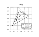
- FIGS. 8 and 9 are explanatory diagrams illustrating an example of a result of converting a color area.
- the shape of the definition color area was changed to perform color conversion in different definition color areas.
- input signals of various components in the reference color area were converted into converted input signals in the respective definition color areas to compare the positions of the chromaticity points of the respective signals with each other.
- definition color areas in examples 1 to 3 were used to respectively perform color conversion on the input signals in the reference color area.
- FIG. 8 illustrates a result of the conversion.
- the reference color area is a color are having NTSC ratio of 60%.
- Each of the definition color areas in the examples 1 to 3 is a color area having NTSC ratio of 45%.
- the definition color areas in the examples 1 to 3 have a different G-chromaticity point from each other within the color areas.
- the red component is smaller and the blue component is larger in the example 2 than those in the example 1, and the red component is smaller and the blue component is larger in the example 3 than those in the example 2.
- a difference between an input signal and a converted input signal in which a color has been converted was the displacement of the chromaticity point to an extent that does not cause any practical problems. Therefore, a displayed image does not change significantly enough to cause practical problems, and display quality degradation is suppressed to an extent that does not cause any practical problems.
- a decrease in saturation of a displayed image is suppressed to an extent that does not cause any practical problems, and display quality degradation is also suppressed. It is also understood that a converted chromaticity point is adjustable by adjusting the G-chromaticity point.
- FIG. 9 illustrates the result of the conversion.
- a comparative example 1 the chromaticity points of respective signals when the same image is displayed by a display device with a display capability whose NTSC ratio is 45% are illustrated.
- converted input signals in the example 4 are approximate to the signals displayed by the display device with the same performance. Also from this point, it is understood that degradation of the display quality of a displayed image is suppressed.
- the liquid-crystal display device 10 according to the embodiment can further reduce power consumption regardless of the mode of converting an RGB signal into an RGBW signal.
- the definition color area is set to a color area where the G (green)-chromaticity point is inside of the reference color area, and therefore a change that is sensed by human eyes can be made smaller.
- the shape of the definition color area relative to the reference color area is not limited to the shape in which the G (green)-chromaticity point is inside of the reference color area.
- the definition color area can have a shape in which the R (red)-chromaticity point is inside of the reference color area, a shape in which the B (blue)-chromaticity point is inside of the reference color area, a shape in which the G-chromaticity point and the R-chromaticity point are inside of the reference color area, a shape in which the G-chromaticity point and the B-chromaticity point are inside of the reference color area, a shape in which the B-chromaticity point and the R-chromaticity point are inside of the reference color area, or a shape in which all the R-chromaticity point, the G-chromaticity point, and the B-chromaticity point are inside of the reference color area.
- the chromaticity point of a pixel color displayed by an image display panel is moved in a direction to be inside of the chromaticity point of the corresponding color in the reference color area.
- a peripheral side that connects pixel colors displayed by the image display panel is shorter than that in the reference color area corresponding to the inside chromaticity point.
- the shape of the reference color area and the definition color area falls within the range of a triangular shape.
- the shape thereof is not limited thereto, and can also be defined within the range of an arbitral shape such as a polygonal shape, a circular shape, and an elliptical shape.
- FIG. 10 is a perspective view of a configuration example of an electronic apparatus according to an application example.
- FIG. 10 illustrates a portable phone as an example of an electronic apparatus 200 .
- FIG. 10 a configuration of the electronic apparatus 200 according to the embodiment is explained.
- the electronic apparatus 200 is a portable phone, and includes a main unit 211 and a display body 212 that is provided to be capable of being opened from and closed to the main unit 211 as illustrated in FIG. 10 .
- the main unit 211 includes an operation button 215 , a transmitter 216 , and a control device 220 .
- the display body 212 includes a liquid-crystal display device 213 and a receiver 217 .
- the liquid-crystal display device 213 displays various information regarding telephone communication on a display screen 214 of the liquid-crystal display device 213 .
- the liquid-crystal display device 213 is configured by the liquid-crystal display device 10 according to the above embodiment.
- the operation button 215 is operated by a user to transmit an operation signal to the control device 220 .
- the control device 220 decides an image to be displayed on the display screen 214 of the liquid-crystal display device 213 , and transmits RGB data of the decided image to the liquid-crystal display device 213 as an input signal.
- the liquid-crystal display device 213 performs the linear conversion, the color conversion processing, the W-generation processing, and the ⁇ -correction that have been described in detail in the above embodiment on the input signal received from the control device 220 . Based on the RGB input signal having undergone each processing, the liquid-crystal display device 213 generates an RGBW output signal and a light-source-device control signal. Based on the output signal and the light-source-device control signal, the liquid-crystal display device 213 displays an image on the display screen 214 .
- a configuration may be employed, in which whether the liquid-crystal display device 213 performs the color conversion processing on the input signal received from the control device 220 is selectable based on setting information held in the control device 220 .
- a configuration can also be employed, in which the control device 220 holds therein a plurality of definition color areas for performing the color conversion processing, which are appropriately selectable. With these configurations, whether the color conversion processing is performed is selected according to the environment of the electronic apparatus 200 , and when the color conversion processing is performed, an appropriate definition color area can be selected among the definition color areas.
- the liquid-crystal display device 213 in the electronic apparatus 200 is configured by the liquid-crystal display device 10 according to the above embodiment. Therefore, a decrease in saturation of an image can be suppressed to an extent that does not cause any practical problems, and power consumption can be reduced.
- Examples of the electronic apparatus 200 according to the present embodiment, to which the liquid-crystal display device 10 according to the above embodiment is applicable, include a clock with a display device, a watch with a display device, a personal computer, a liquid crystal television, a viewfinder-type or monitor direct-view-type videotape recorder, a car navigation device, a pager, an electronic organizer, a calculator, a word processor, a workstation, a videophone, and a POS terminal device, in addition to the portable phone described above.
- the present disclosure includes the following aspects.
- a display device comprising:
- an image display panel in which pixels are arrayed in a two-dimensional matrix, where each of the pixels includes a first sub-pixel that displays a first color, a second sub-pixel that displays a second color, a third sub-pixel that displays a third color, and a fourth sub-pixel that displays white;
- a color conversion device that includes a signal processing unit that generates an output signal for controlling an operation of a pixel of a display unit based on an input signal generated in a reference color area, and a signal output unit that outputs a drive signal of the pixel to the image display panel based on the output signal generated by the signal processing unit;
- planar light-source device that is arranged at a backside of the display unit at an opposite side to an image display surface thereof, and that emits white light toward a substantially entire surface of the display unit;
- the signal processing unit includes a color conversion circuit that converts the input signal in the reference color area into a converted input signal generated in a definition color area where a chromaticity point of at least one of the first color, the second color, and the third color is inside of the reference color area, and a four-color generation circuit that generates the output signal and a light-source-device control signal from the converted input signal converted by the color conversion circuit,
- the signal output unit outputs the drive signal to the first sub-pixel, the second sub-pixel, the third sub-pixel, and the fourth sub-pixel based on the output signal generated by the four-color generation circuit, and
- the light-source-device control unit outputs a drive voltage for emitting the white light on the planar light-source device based on the light-source-device control signal generated by the four-color generation circuit.
- An electronic apparatus comprising:
- control device that transmits the input signal for displaying an image to the display device.
- At least one color area in a color extended space can be narrowed to reduce power consumption, while suppressing a decrease in saturation to an extent that does not cause any practical problems.
Landscapes
- Engineering & Computer Science (AREA)
- Theoretical Computer Science (AREA)
- Physics & Mathematics (AREA)
- General Physics & Mathematics (AREA)
- Computer Hardware Design (AREA)
- General Engineering & Computer Science (AREA)
- Crystallography & Structural Chemistry (AREA)
- Chemical & Material Sciences (AREA)
- Control Of Indicators Other Than Cathode Ray Tubes (AREA)
- Liquid Crystal Display Device Control (AREA)
- Image Processing (AREA)
- Facsimile Image Signal Circuits (AREA)
- Color Image Communication Systems (AREA)
- Liquid Crystal (AREA)
Abstract
Description
Claims (4)
Applications Claiming Priority (2)
| Application Number | Priority Date | Filing Date | Title |
|---|---|---|---|
| JP2013-062503 | 2013-03-25 | ||
| JP2013062503A JP5909206B2 (en) | 2013-03-25 | 2013-03-25 | Display device and electronic device |
Publications (2)
| Publication Number | Publication Date |
|---|---|
| US20140285539A1 US20140285539A1 (en) | 2014-09-25 |
| US9262970B2 true US9262970B2 (en) | 2016-02-16 |
Family
ID=51568830
Family Applications (1)
| Application Number | Title | Priority Date | Filing Date |
|---|---|---|---|
| US14/223,306 Active US9262970B2 (en) | 2013-03-25 | 2014-03-24 | Display device and electronic apparatus |
Country Status (2)
| Country | Link |
|---|---|
| US (1) | US9262970B2 (en) |
| JP (1) | JP5909206B2 (en) |
Families Citing this family (8)
| Publication number | Priority date | Publication date | Assignee | Title |
|---|---|---|---|---|
| JP2015219327A (en) | 2014-05-15 | 2015-12-07 | 株式会社ジャパンディスプレイ | Display device |
| JP2016061858A (en) * | 2014-09-16 | 2016-04-25 | 株式会社ジャパンディスプレイ | Image display panel, image display device, and electronic apparatus |
| KR102268961B1 (en) * | 2014-11-03 | 2021-06-24 | 엘지디스플레이 주식회사 | Method of data conversion and data converter |
| CN104795046B (en) * | 2015-05-13 | 2017-11-07 | 京东方科技集团股份有限公司 | A kind of display base plate and its driving method, display device |
| JP6499511B2 (en) * | 2015-05-19 | 2019-04-10 | 株式会社ジャパンディスプレイ | Display device |
| CN105263009B (en) * | 2015-09-14 | 2017-12-15 | 深圳市华星光电技术有限公司 | A kind of self-adaptive conversion method of image |
| JP6624895B2 (en) * | 2015-11-10 | 2019-12-25 | キヤノン株式会社 | Image processing apparatus, imaging apparatus, control method, and program |
| JP2017107043A (en) | 2015-12-09 | 2017-06-15 | 株式会社ジャパンディスプレイ | Display device |
Citations (5)
| Publication number | Priority date | Publication date | Assignee | Title |
|---|---|---|---|---|
| JP2010156817A (en) | 2008-12-26 | 2010-07-15 | Sharp Corp | Transmission type liquid crystal display device |
| US20100259556A1 (en) * | 2009-04-10 | 2010-10-14 | Hitachi Displays, Ltd. | Display signal conversion apparatus |
| US20120026211A1 (en) * | 2010-07-27 | 2012-02-02 | Sony Corporation | Liquid crystal display apparatus |
| US20130176498A1 (en) * | 2010-10-26 | 2013-07-11 | Sharp Kabushiki Kaisha | Display device |
| JP2014155024A (en) | 2013-02-07 | 2014-08-25 | Japan Display Inc | Color conversion device, display device, electronic apparatus, and color conversion method |
Family Cites Families (1)
| Publication number | Priority date | Publication date | Assignee | Title |
|---|---|---|---|---|
| JP2009217052A (en) * | 2008-03-11 | 2009-09-24 | Sharp Corp | Transmissive liquid crystal display device |
-
2013
- 2013-03-25 JP JP2013062503A patent/JP5909206B2/en active Active
-
2014
- 2014-03-24 US US14/223,306 patent/US9262970B2/en active Active
Patent Citations (5)
| Publication number | Priority date | Publication date | Assignee | Title |
|---|---|---|---|---|
| JP2010156817A (en) | 2008-12-26 | 2010-07-15 | Sharp Corp | Transmission type liquid crystal display device |
| US20100259556A1 (en) * | 2009-04-10 | 2010-10-14 | Hitachi Displays, Ltd. | Display signal conversion apparatus |
| US20120026211A1 (en) * | 2010-07-27 | 2012-02-02 | Sony Corporation | Liquid crystal display apparatus |
| US20130176498A1 (en) * | 2010-10-26 | 2013-07-11 | Sharp Kabushiki Kaisha | Display device |
| JP2014155024A (en) | 2013-02-07 | 2014-08-25 | Japan Display Inc | Color conversion device, display device, electronic apparatus, and color conversion method |
Non-Patent Citations (1)
| Title |
|---|
| Japanese Patent Office Action for Application No. 2013-062503 dated Sep. 1, 2015 (6 pages). |
Also Published As
| Publication number | Publication date |
|---|---|
| JP2014186245A (en) | 2014-10-02 |
| US20140285539A1 (en) | 2014-09-25 |
| JP5909206B2 (en) | 2016-04-26 |
Similar Documents
| Publication | Publication Date | Title |
|---|---|---|
| US9501983B2 (en) | Color conversion device, display device, and color conversion method | |
| US9262970B2 (en) | Display device and electronic apparatus | |
| US7956821B2 (en) | Liquid crystal display unit and system including a plurality of stacked display devices, and drive circuit | |
| US7545395B2 (en) | Color filter, color image display device, and electronic apparatus | |
| TWI549112B (en) | Display device and electronic machine having the same, and method for driving display device | |
| US20160260388A1 (en) | Display device | |
| US9835909B2 (en) | Display device having cyclically-arrayed sub-pixels | |
| US9460675B2 (en) | Display device having signal processing circuits, electronic apparatus having display device, driving method of display device, and signal processing method | |
| US9589534B2 (en) | System and method for converting RGB data to WRGB data | |
| JP2007086783A (en) | Display panel and method for improving display quality thereof | |
| CN100432771C (en) | Electro-optical devices and electronic equipment | |
| TW201415449A (en) | Image display unit, method of driving image display unit, signal generator, signal generation program, and signal generation method | |
| US9830882B2 (en) | Display device and color conversion method | |
| US8184126B2 (en) | Method and apparatus processing pixel signals for driving a display and a display using the same | |
| US10127885B2 (en) | Display device, method for driving the same, and electronic apparatus | |
| US9311886B2 (en) | Display device including signal processing unit that converts an input signal for an input HSV color space, electronic apparatus including the display device, and drive method for the display device | |
| US10157583B2 (en) | Display apparatus and display control method thereof | |
| US11699405B2 (en) | Methods for compensating colors based on virtual chromaticity coordinate points and the related display devices | |
| US20200135143A1 (en) | Image data processing device and display device including the same | |
| US9633614B2 (en) | Display device and a method for driving a display device including four sub-pixels | |
| JP2014048583A (en) | Multi-primary color liquid crystal display device |
Legal Events
| Date | Code | Title | Description |
|---|---|---|---|
| AS | Assignment |
Owner name: JAPAN DISPLAY INC., JAPAN Free format text: ASSIGNMENT OF ASSIGNORS INTEREST;ASSIGNORS:KUROKAWA, TAE;SAKAIGAWA, AKIRA;KABE, MASAAKI;AND OTHERS;SIGNING DATES FROM 20140313 TO 20140314;REEL/FRAME:032508/0989 |
|
| FEPP | Fee payment procedure |
Free format text: PAYOR NUMBER ASSIGNED (ORIGINAL EVENT CODE: ASPN); ENTITY STATUS OF PATENT OWNER: LARGE ENTITY |
|
| STCF | Information on status: patent grant |
Free format text: PATENTED CASE |
|
| MAFP | Maintenance fee payment |
Free format text: PAYMENT OF MAINTENANCE FEE, 4TH YEAR, LARGE ENTITY (ORIGINAL EVENT CODE: M1551); ENTITY STATUS OF PATENT OWNER: LARGE ENTITY Year of fee payment: 4 |
|
| MAFP | Maintenance fee payment |
Free format text: PAYMENT OF MAINTENANCE FEE, 8TH YEAR, LARGE ENTITY (ORIGINAL EVENT CODE: M1552); ENTITY STATUS OF PATENT OWNER: LARGE ENTITY Year of fee payment: 8 |
|
| AS | Assignment |
Owner name: MAGNOLIA WHITE CORPORATION, JAPAN Free format text: ASSIGNMENT OF ASSIGNORS INTEREST;ASSIGNOR:JAPAN DISPLAY INC.;REEL/FRAME:072130/0313 Effective date: 20250625 Owner name: MAGNOLIA WHITE CORPORATION, JAPAN Free format text: ASSIGNMENT OF ASSIGNOR'S INTEREST;ASSIGNOR:JAPAN DISPLAY INC.;REEL/FRAME:072130/0313 Effective date: 20250625 |