US9255990B2 - Method and apparatus for generating volume image - Google Patents
Method and apparatus for generating volume image Download PDFInfo
- Publication number
- US9255990B2 US9255990B2 US13/892,862 US201313892862A US9255990B2 US 9255990 B2 US9255990 B2 US 9255990B2 US 201313892862 A US201313892862 A US 201313892862A US 9255990 B2 US9255990 B2 US 9255990B2
- Authority
- US
- United States
- Prior art keywords
- sub
- volume image
- volume
- region
- image
- Prior art date
- Legal status (The legal status is an assumption and is not a legal conclusion. Google has not performed a legal analysis and makes no representation as to the accuracy of the status listed.)
- Active, expires
Links
Images


Classifications
-
- G—PHYSICS
- G01—MEASURING; TESTING
- G01S—RADIO DIRECTION-FINDING; RADIO NAVIGATION; DETERMINING DISTANCE OR VELOCITY BY USE OF RADIO WAVES; LOCATING OR PRESENCE-DETECTING BY USE OF THE REFLECTION OR RERADIATION OF RADIO WAVES; ANALOGOUS ARRANGEMENTS USING OTHER WAVES
- G01S7/00—Details of systems according to groups G01S13/00, G01S15/00, G01S17/00
- G01S7/52—Details of systems according to groups G01S13/00, G01S15/00, G01S17/00 of systems according to group G01S15/00
- G01S7/52017—Details of systems according to groups G01S13/00, G01S15/00, G01S17/00 of systems according to group G01S15/00 particularly adapted to short-range imaging
- G01S7/52053—Display arrangements
- G01S7/52057—Cathode ray tube displays
- G01S7/5206—Two-dimensional coordinated display of distance and direction; B-scan display
- G01S7/52063—Sector scan display
-
- G—PHYSICS
- G01—MEASURING; TESTING
- G01S—RADIO DIRECTION-FINDING; RADIO NAVIGATION; DETERMINING DISTANCE OR VELOCITY BY USE OF RADIO WAVES; LOCATING OR PRESENCE-DETECTING BY USE OF THE REFLECTION OR RERADIATION OF RADIO WAVES; ANALOGOUS ARRANGEMENTS USING OTHER WAVES
- G01S15/00—Systems using the reflection or reradiation of acoustic waves, e.g. sonar systems
- G01S15/88—Sonar systems specially adapted for specific applications
- G01S15/89—Sonar systems specially adapted for specific applications for mapping or imaging
- G01S15/8906—Short-range imaging systems; Acoustic microscope systems using pulse-echo techniques
- G01S15/8995—Combining images from different aspect angles, e.g. spatial compounding
-
- A—HUMAN NECESSITIES
- A61—MEDICAL OR VETERINARY SCIENCE; HYGIENE
- A61B—DIAGNOSIS; SURGERY; IDENTIFICATION
- A61B8/00—Diagnosis using ultrasonic, sonic or infrasonic waves
- A61B8/13—Tomography
- A61B8/14—Echo-tomography
-
- G—PHYSICS
- G01—MEASURING; TESTING
- G01S—RADIO DIRECTION-FINDING; RADIO NAVIGATION; DETERMINING DISTANCE OR VELOCITY BY USE OF RADIO WAVES; LOCATING OR PRESENCE-DETECTING BY USE OF THE REFLECTION OR RERADIATION OF RADIO WAVES; ANALOGOUS ARRANGEMENTS USING OTHER WAVES
- G01S15/00—Systems using the reflection or reradiation of acoustic waves, e.g. sonar systems
- G01S15/88—Sonar systems specially adapted for specific applications
- G01S15/89—Sonar systems specially adapted for specific applications for mapping or imaging
- G01S15/8906—Short-range imaging systems; Acoustic microscope systems using pulse-echo techniques
- G01S15/8993—Three dimensional imaging systems
-
- G—PHYSICS
- G06—COMPUTING OR CALCULATING; COUNTING
- G06T—IMAGE DATA PROCESSING OR GENERATION, IN GENERAL
- G06T15/00—3D [Three Dimensional] image rendering
- G06T15/08—Volume rendering
-
- G—PHYSICS
- G06—COMPUTING OR CALCULATING; COUNTING
- G06T—IMAGE DATA PROCESSING OR GENERATION, IN GENERAL
- G06T2207/00—Indexing scheme for image analysis or image enhancement
- G06T2207/10—Image acquisition modality
- G06T2207/10132—Ultrasound image
- G06T2207/10136—3D ultrasound image
Definitions
- the present invention relates to a method and apparatus for generating a volume image of a target body. More particularly, the present invention relates to a method and apparatus for generating a volume image by connecting sub-volume images of a target body to one another.
- Ultrasonic apparatuses are equipment for observing the interior structure of an organic body. Ultrasonic apparatuses are noninvasive inspecting apparatuses, and show structural details and interior tissue of a body and the flow of a fluid in the body.
- Ultrasonic apparatuses acquire an image of an interior structure of a target body by transmitting an ultrasonic signal to the target body and receiving a response signal reflected from the target body.
- Ultrasonic apparatuses may generate a volume image, that is, a three-dimensional (3D) image, of a target body, and an examiner may inspect the target body three-dimensionally via the volume image.
- a volume image that is, a three-dimensional (3D) image
- the present invention provides generation of a reliable volume image due to effective removal of stitch artifacts included in a volume image of a target body.
- a volume image generating method including transmitting an ultrasonic signal to a target body divided into a plurality of regions and generating a first sub-volume image corresponding to a first region from among the plurality of regions of the target body, based on a response signal reflected from the target body; generating a second sub-volume image corresponding to a second region contacting the first region from among the plurality of regions; connecting the second sub-volume image to the first sub-volume image according to a location relationship between the first region and the second region of the target body; and re-generating the second sub-volume image based on a concordance rate between sectional images of the first and second sub-volume images that contact each other, and connecting the re-generated second sub-volume image to the first sub-volume image.
- the volume image generating method may further include, when the concordance rate between the sectional images of the first and second sub-volume images that contact each other exceeds a preset value, generating a third sub-volume image corresponding to a third region contacting the second region from among the plurality of regions of the target body and connecting the third sub-volume image to the re-generated second sub-volume image.
- the connecting of the re-generated second sub-volume image to the first sub-volume image may include automatically re-generating the second sub-volume image when the concordance rate is less than the preset value.
- the volume image generating method may further include generating sub-volume images respectively corresponding to the plurality of regions and connecting the sub-volume images to one another to generate a volume image of the target body.
- the connecting of the re-generated second sub-volume image to the first sub-volume image may include acquiring the concordance rate between the sectional images of the first and second sub-volume images that contact each other, by using a SSD, a CC, or MI.
- the volume image generating method may further include displaying a first figure corresponding to the generated first sub-volume image; and connecting a second figure corresponding to the generated second sub-volume image to the first figure according to a location relationship between the first region and the second region of the target body and displaying the connected first and second figures.
- the volume image generating method may further include mapping the concordance rate between the sectional images of the first and second sub-volume images that contact each other with a color scale and displaying a result of the mapping on the second figure.
- a volume image generating apparatus including a probe which transmits an ultrasonic signal to a target body divided into a plurality of regions and receives a response signal reflected from the target body; and an image control unit which generates a first sub-volume image and a second sub-volume image corresponding respectively to a first region and a second region contacting the first region, from among the plurality of regions based on the response signal, and connects the second sub-volume image to the first sub-volume image according to a location relationship between the first region and the second region, wherein the image control unit re-generates the second sub-volume image based on a concordance rate between sectional images of the first and second sub-volume images that contact each other, and connects the re-generated second sub-volume image to the first sub-volume image.
- the image control unit may generate a third sub-volume image corresponding to a third region contacting the second region from among the plurality of regions and connect the third sub-volume image to the re-generated second sub-volume image.
- the image control unit may generate sub-volume images respectively corresponding to the plurality of regions and connect the sub-volume images to one another to generate a volume image of the target body.
- the image control unit may automatically re-generate the second sub-volume image.
- the image control unit may acquire the concordance rate between the sectional images of the first and second sub-volume images that contact each other, by using an SSD, a CC, or MI.
- the volume image generating apparatus may further include a display unit which displays a first figure corresponding to the generated first sub-volume image, connects a second figure corresponding to the generated second sub-volume image to the first figure according to a location relationship between the first region and the second region, and displays the connected first and second figures.
- the display unit may map the concordance rate between the sectional images of the first and second sub-volume images that contact each other with a color scale and display a result of the mapping on the second figure.
- a computer-readable recording medium having recorded thereon a program for executing the volume image generating method.
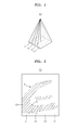
- FIG. 1 illustrates a target body divided into a plurality of regions
- FIG. 2 illustrates a volume image generated according to a conventional volume image generating method
- FIG. 3 is a configuration diagram of a volume image generating apparatus according to an embodiment of the present invention.
- FIG. 4 illustrates a first sub-volume image and a second sub-volume image in the volume image generating apparatus illustrated in FIG. 3 ;
- FIG. 5 illustrates a first figure corresponding to a first sub-volume image and a second figure corresponding to a second sub-volume image in the volume image generating apparatus illustrated in FIG. 3 ;
- FIG. 6 is a flowchart of a volume image generating method according to an embodiment of the present invention.
- FIG. 7 is a flowchart of a volume image generating method according to another embodiment of the present invention.
- unit may refer to, but is not limited to, a software or hardware component, such as a Field Programmable Gate Array (FPGA) or Application Specific Integrated Circuit (ASIC), which performs certain tasks.
- a unit may be configured to reside on an addressable storage medium and configured to execute one or more processors.
- examples of a unit may include components, such as software components, object-oriented software components, class components and task components, processes, functions, attributes, procedures, subroutines, segments of program code, drivers, firmware, microcode, circuitry, data, database, data structures, tables, arrays, and variables.
- the functionality provided in the components and units may be combined into fewer components and units or further separated into additional components and units.
- FIG. 1 illustrates a target body 10 divided into a plurality of regions, namely, first, second, third, and fourth regions 11 , 13 , 15 , and 17 .
- the target body 10 used herein denotes blood flow in a human body, various organs of the human body, or a specific part of the human body, from which an ultrasonic image is to be acquired.
- the target body 10 is divided into the first region 11 , the second region 13 , the third region 15 , and the fourth region 17 .
- the target body 10 is divided into the four regions 11 , 13 , 15 , and 17 in FIG. 1 , the number of regions into which the target body 10 is divided is not limited to 4.
- a volume image for the entire target body 10 is generated at a time.
- the volume image generated according to this method has a low spatial resolution and a low temporal resolution.
- the target body 10 may be divided into the first, second, third, and fourth regions 11 , 13 , 15 , and 17 , and respective sub-volume images for the first, second, third, and fourth regions 11 , 13 , 15 , and 17 may be connected to one another to generate the volume image of the target body 10 .
- FIG. 2 illustrates a volume image 20 generated according to a conventional volume image generating method.
- the volume image 20 includes an ultrasonic image 29 for a target body.
- the volume image 20 is generated by connecting sub-volume images 21 , 23 , 25 , and 27 respectively corresponding to a plurality of regions.
- the volume image 20 generated in this way may include stitch artifacts indicated by reference characters A, B, and C.
- the stitch artifacts A, B, and C may be formed by discontinuity between sectional images of every two adjacent ones of the sub-volume images 21 , 23 , 25 , and 27 .
- An examiner may not accurately inspect the target body 10 through the volume image 20 of FIG. 2 .
- FIG. 3 is a configuration diagram of a volume image generating apparatus 100 according to an embodiment of the present invention.
- the volume image generating apparatus 100 may include a probe 110 and an image control unit 120 . It will be apparent to one of ordinary skill in the art that the image control unit 120 may include a plurality of modules that perform a function of the image control unit 120 .
- the probe 110 includes a plurality of elements corresponding to piezoelectric elements, and the probe 110 transmits an ultrasonic signal to the target body 10 and receives a response signal reflected from the target body 10 .
- the probe 110 of the volume image generating apparatus 100 may be a probe 110 for acquiring a three-dimensional (3D) image.
- the probe 110 may transmit an ultrasonic signal to each of the first, second, third, and fourth regions 11 , 13 , 15 , and 17 and may receive response signals respectively reflected from the first, second, third, and fourth regions 11 , 13 , 15 , and 17 .
- the image control unit 120 generates a first sub-volume image corresponding to the first region 11 of the target body 10 , based on the response signal reflected from the target body 10 .
- the image control unit 120 also generates a second sub-volume image corresponding to the second region 13 , which contacts the first region 11 , based on the response signal reflected from the target body 10 .
- the transmission of the ultrasonic signal and the reception of the response signal in the probe 110 may be performed every time each sub-volume image is generated.
- the image control unit 120 may generate the first sub-volume image at a specific time point of an electrocardiogram (ECG) period and generate the second sub-volume image at a next specific time point of the ECG period. Accordingly, an error rate between sub-volume images may be reduced.
- ECG electrocardiogram
- the image control unit 120 After the image control unit 120 generates the first sub-volume image corresponding to the first region 11 of FIG. 1 , it generates the second sub-volume image corresponding to the second region 13 of FIG. 1 that contacts the first region 11 .
- the image control unit 120 connects the second sub-volume image to the first sub-volume image according to a location relationship between the first region 11 and the second region 13 of the target body 10 .
- the image control unit 120 may connect the second sub-volume image to the right side of the first sub-volume image.
- the image control unit 120 acquires a concordance rate between sectional images of the first and second sub-volume images that contact each other. Next, the image control unit 120 re-generates the second sub-volume image according to the concordance rate and connects the second sub-volume image to the first sub-volume image.
- FIG. 4 illustrates a first sub-volume image 210 and a second sub-volume image 230 in the volume image generating apparatus 100 illustrated in FIG. 3 .
- the first sub-volume image 210 of FIG. 4 corresponds to the first region 11 of the target body 10 illustrated in FIG. 1
- the second sub-volume image 230 corresponds to the second region 13 of the target body 10 .
- sections of the first and second sub-volume images 210 and 230 that are connected to each other include sectional images 212 and 232 , respectively.
- the image control unit 120 acquires a concordance rate between the sectional image 212 of the first sub-volume image 210 and the sectional image 232 of the second sub-volume image 230 .
- the image control unit 120 may acquire the concordance rate between the sectional images 212 and 232 of the first and second sub-volume images 210 and 230 that contact each other, by using a sum of squared differences (SSD), a correlation coefficient (CC), or mutual information (MI). Since the use of the SSD, the CC, and the MI in order to determine similarity between images is common in the art, a detailed description thereof is omitted.
- SSD sum of squared differences
- CC correlation coefficient
- MI mutual information
- the image control unit 120 automatically re-generates the second sub-volume image 230 .
- the image control unit 120 may show an examiner the concordance rate between the sectional image 212 of the first sub-volume image 210 and the sectional image 232 of the second sub-volume image 230 , and may re-generate the second sub-volume image 230 under the control of the examiner.
- the image control unit 120 when the concordance rate between the sectional image 212 of the first sub-volume image 210 and the sectional image 232 of the second sub-volume image 230 exceeds the preset value, the image control unit 120 generates a third sub-volume image corresponding to the third region 15 contacting the second region 13 and connects the third sub-volume image to the second sub-volume image.
- the image control unit 120 re-generates the third sub-volume image or generates a fourth sub-volume image, based on a concordance rate between sectional images of the third and second sub-volume images that contact each other.
- the volume image generating apparatus 100 of FIG. 3 sequentially generates respective sub-volume images of the first through n-th regions.
- a concordance rate between a sectional image of a sub-volume image and that of a previous sub-volume image is less than a preset value
- the volume image generating apparatus 100 of FIG. 3 does not generate a next sub-volume image but re-generates the current sub-volume image. Accordingly, stitch artifacts between sub-volume images may be removed, and a reliable volume image may be provided to the examiner.
- FIG. 5 illustrates a first FIG. 310 corresponding to a first sub-volume image and a second FIG. 330 corresponding to a second sub-volume image in the volume image generating apparatus 100 of FIG. 3 .
- the volume image generating apparatus 100 may show an examiner the progress of generation of the volume image of the target body 10 and a concordance rate between sectional images of sub-frames.
- the volume image generating apparatus 100 may further include a display unit (not shown).
- the display unit may display, to the examiner, a sub-volume image and a volume image generated by the image control unit 120 .
- the display unit may also display the first FIG. 310 corresponding to the first sub-volume image generated by the image control unit 120 and may connect the second FIG. 330 corresponding to the second sub-volume image generated by the image control unit 120 to the first FIG. 310 according to the location relationship between the first region 11 and the second region 13 of the target body 10 and display the connected first and second FIGS. 310 and 330 .
- the first FIG. 310 of FIG. 5 corresponds to the first sub-volume image 210 of FIG. 4
- the second FIG. 330 corresponds to the second sub-volume image 230 of FIG. 4 .
- the display unit does not display a third FIG. 350 corresponding to the third sub-volume image or a fourth FIG. 370 corresponding to the fourth sub-volume image and only displays the first and second FIGS. 310 and 330 of the already-generated first and second sub-volume images, thereby displaying the progress of generation of the volume image to a user.
- the display unit may map the concordance rate between the sectional images of the first and second sub-volume images that contact each other with a color scale 390 and may display a result of the mapping on the second FIG. 330 .
- the display unit may acquire a color corresponding to the concordance rate between the sectional images of the first and second sub-volume images that contact each other from the color scale 390 , and may display the second FIG. 330 in the acquired color.
- the color scale 390 includes a plurality of colors corresponding to a plurality of concordance rates.
- the examiner may check the color of a figure displayed on the display unit and can determine intuitively whether a sub-volume image corresponding to the figure should be re-produced or not.
- FIG. 6 is a flowchart of a volume image generating method according to an embodiment of the present invention.
- the volume image generating method includes operations sequentially performed by the volume image generating apparatus 100 of FIG. 3 . Accordingly, the description given above with respect to the volume image generating apparatus 100 of FIG. 3 may also be applied to the volume image generating method of FIG. 6 .
- the volume image generating apparatus 100 transmits an ultrasonic signal to the target body 10 divided into the first, second, third, and fourth regions 11 , 13 , 15 , and 17 .
- the volume image generating apparatus 100 may transmit the ultrasonic signal to each of the first, second, third, and fourth regions 11 , 13 , 15 , and 17 , so the transmission is performed four times.
- the volume image generating apparatus 100 receives a response signal reflected from the target body 10 .
- the volume image generating apparatus 100 In operation S 30 , the volume image generating apparatus 100 generates a first sub-volume image corresponding to the first region 11 of the target body 10 .
- the volume image generating apparatus 100 In operation S 40 , the volume image generating apparatus 100 generates a second sub-volume image corresponding to the second region 13 of the target body 10 contacting the first region 11 .
- the volume image generating apparatus 100 connects the second sub-volume image to the first sub-volume image according to a location relationship between the first region 11 and the second region 13 of the target body 10 .
- the volume image generating apparatus 100 acquires a concordance rate between sectional images of the first and second sub-volume images.
- the volume image generating apparatus 100 re-generates the second sub-volume image based on the concordance rate between the sectional images of the first and second sub-volume images and connects the second sub-volume image to the first sub-volume image.
- FIG. 7 is a flowchart of a volume image generating method according to another embodiment of the present invention.
- the volume image generating apparatus 100 divides the target body 10 into n (n denotes an integer greater than 1) regions and transmits an ultrasonic signal to the target body 10 divided into the n regions.
- the volume image generating apparatus 100 may transmit the ultrasonic signal to only an i-th (i denotes an integer ranging from 1 to n) region from among the n regions of the target body 10 .
- the volume image generating apparatus 100 receives a response signal reflected from the target body 10 .
- the volume image generating apparatus 100 may receive a response signal reflected from the i-th region from among the n regions of the target body 10 .
- the volume image generating apparatus 100 In operation S 130 , the volume image generating apparatus 100 generates an i-th sub-volume image corresponding to the i-th region.
- the volume image generating apparatus 100 generates an (i+1)th sub-volume image.
- the volume image generating apparatus 100 may perform a process of transmitting the ultrasonic signal to an (i+1)th region of the target body 10 and receiving a response signal reflected from the (i+1)th region.
- the volume image generating apparatus 100 connects the (i+1)th sub-volume image to the i-th sub-volume image.
- the volume image generating apparatus 100 acquires a concordance rate between sectional images of the i-th and (i+1)th sub-volume images.
- the volume image generating apparatus 100 re-generates the (i+1)th sub-volume image based on the acquired concordance rate and connects the (i+1)th sub-volume image to the i-th sub-volume image.
- the volume image generating apparatus 100 does not generate an (i+2)th sub-volume image but re-generates the (i+1)th sub-volume image.
- the volume image generating apparatus 100 determines whether i+1 is equal to n. This corresponds to an ascertainment of whether the (i+1)th sub-volume image is a sub-volume image corresponding to the n-th region from among the n regions of the target body 10 .
- the volume image generating apparatus 100 when i+1 is equal to n, the volume image generating apparatus 100 generates a volume image by connecting n sub-volume images respectively corresponding to the n regions of the target body 10 .
- the volume image generating apparatus 100 increases the value of i by one, and the method goes back to operation S 140 , in order to generate a sub-volume image corresponding to an (i+2)th region from among the n regions of the target body 10 and connect the generated sub-volume image to the (i+1)th sub-volume image.
- Examples of the computer readable recording medium include magnetic storage media (e.g., ROM, floppy disks, hard disks, etc.), optical recording media (e.g., CD-ROMs, or DVDs), etc.
- magnetic storage media e.g., ROM, floppy disks, hard disks, etc.
- optical recording media e.g., CD-ROMs, or DVDs
Landscapes
- Engineering & Computer Science (AREA)
- Physics & Mathematics (AREA)
- Radar, Positioning & Navigation (AREA)
- Remote Sensing (AREA)
- General Physics & Mathematics (AREA)
- Acoustics & Sound (AREA)
- Computer Networks & Wireless Communication (AREA)
- Computer Graphics (AREA)
- Theoretical Computer Science (AREA)
- Health & Medical Sciences (AREA)
- Life Sciences & Earth Sciences (AREA)
- Nuclear Medicine, Radiotherapy & Molecular Imaging (AREA)
- Molecular Biology (AREA)
- Pathology (AREA)
- Radiology & Medical Imaging (AREA)
- Biomedical Technology (AREA)
- Heart & Thoracic Surgery (AREA)
- Medical Informatics (AREA)
- Biophysics (AREA)
- Surgery (AREA)
- Animal Behavior & Ethology (AREA)
- General Health & Medical Sciences (AREA)
- Public Health (AREA)
- Veterinary Medicine (AREA)
- Ultra Sonic Daignosis Equipment (AREA)
Abstract
Description
Claims (15)
Applications Claiming Priority (2)
| Application Number | Priority Date | Filing Date | Title |
|---|---|---|---|
| KR10-2012-0051064 | 2012-05-14 | ||
| KR1020120051064A KR101323334B1 (en) | 2012-05-14 | 2012-05-14 | Apparatus and method for generating volume image |
Publications (2)
| Publication Number | Publication Date |
|---|---|
| US20130301381A1 US20130301381A1 (en) | 2013-11-14 |
| US9255990B2 true US9255990B2 (en) | 2016-02-09 |
Family
ID=48288763
Family Applications (1)
| Application Number | Title | Priority Date | Filing Date |
|---|---|---|---|
| US13/892,862 Active 2034-05-14 US9255990B2 (en) | 2012-05-14 | 2013-05-13 | Method and apparatus for generating volume image |
Country Status (3)
| Country | Link |
|---|---|
| US (1) | US9255990B2 (en) |
| EP (1) | EP2665041B1 (en) |
| KR (1) | KR101323334B1 (en) |
Families Citing this family (1)
| Publication number | Priority date | Publication date | Assignee | Title |
|---|---|---|---|---|
| JP6632829B2 (en) * | 2014-08-27 | 2020-01-22 | キヤノンメディカルシステムズ株式会社 | Medical image processing apparatus and medical image processing method |
Citations (8)
| Publication number | Priority date | Publication date | Assignee | Title |
|---|---|---|---|---|
| US6775405B1 (en) * | 2000-09-29 | 2004-08-10 | Koninklijke Philips Electronics, N.V. | Image registration system and method using cross-entropy optimization |
| US20070179377A1 (en) * | 2003-12-11 | 2007-08-02 | Koninklijke Philips Electronic, N.V. | Elastic image registration |
| US20080037843A1 (en) | 2006-08-11 | 2008-02-14 | Accuray Incorporated | Image segmentation for DRR generation and image registration |
| JP2009112468A (en) | 2007-11-05 | 2009-05-28 | Toshiba Corp | Image alignment apparatus and method, and image alignment program |
| JP2009131420A (en) | 2007-11-29 | 2009-06-18 | Toshiba Corp | Ultrasound diagnostic imaging equipment |
| WO2010015957A1 (en) | 2008-08-04 | 2010-02-11 | Koninklijke Philips Electronics, N.V. | Automatic pre-alignment for registration of medical images |
| EP2189812A1 (en) | 2008-11-25 | 2010-05-26 | Medison Co., Ltd. | Providing volume information on a periodically moving target object in an ultrasound system |
| JP2011156286A (en) | 2010-02-03 | 2011-08-18 | Toshiba Corp | Ultrasonic diagnosis apparatus and ultrasonic image displaying program |
-
2012
- 2012-05-14 KR KR1020120051064A patent/KR101323334B1/en active Active
-
2013
- 2013-04-17 EP EP13164033.6A patent/EP2665041B1/en active Active
- 2013-05-13 US US13/892,862 patent/US9255990B2/en active Active
Patent Citations (8)
| Publication number | Priority date | Publication date | Assignee | Title |
|---|---|---|---|---|
| US6775405B1 (en) * | 2000-09-29 | 2004-08-10 | Koninklijke Philips Electronics, N.V. | Image registration system and method using cross-entropy optimization |
| US20070179377A1 (en) * | 2003-12-11 | 2007-08-02 | Koninklijke Philips Electronic, N.V. | Elastic image registration |
| US20080037843A1 (en) | 2006-08-11 | 2008-02-14 | Accuray Incorporated | Image segmentation for DRR generation and image registration |
| JP2009112468A (en) | 2007-11-05 | 2009-05-28 | Toshiba Corp | Image alignment apparatus and method, and image alignment program |
| JP2009131420A (en) | 2007-11-29 | 2009-06-18 | Toshiba Corp | Ultrasound diagnostic imaging equipment |
| WO2010015957A1 (en) | 2008-08-04 | 2010-02-11 | Koninklijke Philips Electronics, N.V. | Automatic pre-alignment for registration of medical images |
| EP2189812A1 (en) | 2008-11-25 | 2010-05-26 | Medison Co., Ltd. | Providing volume information on a periodically moving target object in an ultrasound system |
| JP2011156286A (en) | 2010-02-03 | 2011-08-18 | Toshiba Corp | Ultrasonic diagnosis apparatus and ultrasonic image displaying program |
Non-Patent Citations (4)
| Title |
|---|
| Extended European Search Report issued in European Patent Application No. EP 13164033.6 dated Oct. 1, 2013. |
| Korean Notice of Allowance, w/ English translation thereof, issued in Korean Patent Application No. KR 10-2012-0051064 dated Oct. 7, 2013. |
| Korean Office Action, w/ English translation thereof, issued in Korean Patent Application No. KR 10-2012-0051064 dated Feb. 28, 2013. |
| S. Brekke et al., "Real-time volume stitching in 4D echocardiography," 2005 IEEE Ultrasonics Symposium; pp. 1228-1231; XP010899047. |
Also Published As
| Publication number | Publication date |
|---|---|
| EP2665041B1 (en) | 2019-01-23 |
| US20130301381A1 (en) | 2013-11-14 |
| EP2665041A1 (en) | 2013-11-20 |
| KR101323334B1 (en) | 2013-10-29 |
Similar Documents
| Publication | Publication Date | Title |
|---|---|---|
| US11730447B2 (en) | Haptic feedback for ultrasound image acquisition | |
| CN114615937B (en) | System and method for vascular imaging | |
| US11364013B2 (en) | Ultrasound imaging system with a neural network for image formation and tissue characterization | |
| CN113950293B (en) | Methods and systems for guiding the acquisition of cranial ultrasound data | |
| JP6535088B2 (en) | Quality Metrics for Multibeat Echocardiography Acquisition for Immediate User Feedback | |
| CN104706384B (en) | Method and apparatus for obtaining elasticity information about a region of interest using shear waves | |
| JP4562028B2 (en) | Medical imaging method and system | |
| US10792009B2 (en) | Ultrasonic diagnostic apparatus, ultrasonic image display apparatus, and medical image diagnostic apparatus | |
| US11701091B2 (en) | Ultrasound analysis apparatus and method for tissue elasticity and viscosity based on the hormonic signals | |
| US10952705B2 (en) | Method and system for creating and utilizing a patient-specific organ model from ultrasound image data | |
| US20160093044A1 (en) | Medical diagnosis apparatus, image processing apparatus, and method for image processing | |
| US20140153358A1 (en) | Medical imaging system and method for providing imaging assitance | |
| US10667796B2 (en) | Method and system for registering a medical image with a graphical model | |
| US20230320694A1 (en) | Graphical user interface for providing ultrasound imaging guidance | |
| CN113194837A (en) | System and method for frame indexing and image review | |
| CN106030657B (en) | Motion-adaptive visualization in medical 4D imaging | |
| CN108852409B (en) | Method and system for enhanced visualization of moving structures through transplanar ultrasound images | |
| US9255990B2 (en) | Method and apparatus for generating volume image | |
| US20240057970A1 (en) | Ultrasound image acquisition, tracking and review | |
| US11166700B2 (en) | Optimal ultrasound-based organ segmentation | |
| US9251611B2 (en) | Method and apparatus for medical image display, and user interface screen generating method | |
| US11850101B2 (en) | Medical image diagnostic apparatus, medical image processing apparatus, and medical image processing method | |
| EP2674108A1 (en) | Ultrasound diagnosis method and apparatus using electrocardiogram | |
| EP2722006A1 (en) | Method and apparatus for generating volume image | |
| JP2024110447A (en) | Ultrasound diagnostic device, ultrasound diagnostic method, and program |
Legal Events
| Date | Code | Title | Description |
|---|---|---|---|
| AS | Assignment |
Owner name: SAMSUNG MEDISON CO., LTD., KOREA, REPUBLIC OF Free format text: ASSIGNMENT OF ASSIGNORS INTEREST;ASSIGNORS:SONG, JOO-HYUN;LEE, JIN-YONG;REEL/FRAME:030406/0823 Effective date: 20130419 |
|
| AS | Assignment |
Owner name: SAMSUNG MEDISON CO., LTD., KOREA, REPUBLIC OF Free format text: CORRECTIVE ASSIGNMENT TO CORRECT THE ASSIGNEE ADDRESS PREVIOUSLY RECORDED AT REEL: 030406 FRAME: 0823. ASSIGNOR(S) HEREBY CONFIRMS THE ASSIGNMENT;ASSIGNORS:SONG, JOO-HYUN;LEE, JIN-YONG;REEL/FRAME:036551/0436 Effective date: 20130419 |
|
| FEPP | Fee payment procedure |
Free format text: PAYOR NUMBER ASSIGNED (ORIGINAL EVENT CODE: ASPN); ENTITY STATUS OF PATENT OWNER: LARGE ENTITY |
|
| STCF | Information on status: patent grant |
Free format text: PATENTED CASE |
|
| MAFP | Maintenance fee payment |
Free format text: PAYMENT OF MAINTENANCE FEE, 4TH YEAR, LARGE ENTITY (ORIGINAL EVENT CODE: M1551); ENTITY STATUS OF PATENT OWNER: LARGE ENTITY Year of fee payment: 4 |
|
| MAFP | Maintenance fee payment |
Free format text: PAYMENT OF MAINTENANCE FEE, 8TH YEAR, LARGE ENTITY (ORIGINAL EVENT CODE: M1552); ENTITY STATUS OF PATENT OWNER: LARGE ENTITY Year of fee payment: 8 |