US9255523B2 - Fastening element and de-icing device of an aircraft gas-turbine engine - Google Patents

Fastening element and de-icing device of an aircraft gas-turbine engine Download PDF

Info

Publication number
US9255523B2
US9255523B2 US13/739,772 US201313739772A US9255523B2 US 9255523 B2 US9255523 B2 US 9255523B2 US 201313739772 A US201313739772 A US 201313739772A US 9255523 B2 US9255523 B2 US 9255523B2
Authority
US
United States
Prior art keywords
accordance
icing device
tube element
struts
central axis
Prior art date
Legal status (The legal status is an assumption and is not a legal conclusion. Google has not performed a legal analysis and makes no representation as to the accuracy of the status listed.)
Active, expires
Application number
US13/739,772
Other versions
US20130180227A1 (en
Inventor
Predrag Todorovic
Gustavo Araujo
Current Assignee (The listed assignees may be inaccurate. Google has not performed a legal analysis and makes no representation or warranty as to the accuracy of the list.)
Rolls Royce Deutschland Ltd and Co KG
Original Assignee
Rolls Royce Deutschland Ltd and Co KG
Priority date (The priority date is an assumption and is not a legal conclusion. Google has not performed a legal analysis and makes no representation as to the accuracy of the date listed.)
Filing date
Publication date
Application filed by Rolls Royce Deutschland Ltd and Co KG filed Critical Rolls Royce Deutschland Ltd and Co KG
Assigned to ROLLS-ROYCE DEUTSCHLAND LTD & CO KG reassignment ROLLS-ROYCE DEUTSCHLAND LTD & CO KG ASSIGNMENT OF ASSIGNORS INTEREST (SEE DOCUMENT FOR DETAILS). Assignors: TODOROVIC, PREDRAG, ARAUJO, GUSTAVO
Publication of US20130180227A1 publication Critical patent/US20130180227A1/en
Application granted granted Critical
Publication of US9255523B2 publication Critical patent/US9255523B2/en
Active legal-status Critical Current
Adjusted expiration legal-status Critical

Links

Images

Classifications

    • FMECHANICAL ENGINEERING; LIGHTING; HEATING; WEAPONS; BLASTING
    • F02COMBUSTION ENGINES; HOT-GAS OR COMBUSTION-PRODUCT ENGINE PLANTS
    • F02CGAS-TURBINE PLANTS; AIR INTAKES FOR JET-PROPULSION PLANTS; CONTROLLING FUEL SUPPLY IN AIR-BREATHING JET-PROPULSION PLANTS
    • F02C7/00Features, components parts, details or accessories, not provided for in, or of interest apart form groups F02C1/00 - F02C6/00; Air intakes for jet-propulsion plants
    • F02C7/20Mounting or supporting of plant; Accommodating heat expansion or creep
    • FMECHANICAL ENGINEERING; LIGHTING; HEATING; WEAPONS; BLASTING
    • F02COMBUSTION ENGINES; HOT-GAS OR COMBUSTION-PRODUCT ENGINE PLANTS
    • F02CGAS-TURBINE PLANTS; AIR INTAKES FOR JET-PROPULSION PLANTS; CONTROLLING FUEL SUPPLY IN AIR-BREATHING JET-PROPULSION PLANTS
    • F02C7/00Features, components parts, details or accessories, not provided for in, or of interest apart form groups F02C1/00 - F02C6/00; Air intakes for jet-propulsion plants
    • F02C7/04Air intakes for gas-turbine plants or jet-propulsion plants
    • F02C7/047Heating to prevent icing
    • FMECHANICAL ENGINEERING; LIGHTING; HEATING; WEAPONS; BLASTING
    • F02COMBUSTION ENGINES; HOT-GAS OR COMBUSTION-PRODUCT ENGINE PLANTS
    • F02KJET-PROPULSION PLANTS
    • F02K3/00Plants including a gas turbine driving a compressor or a ducted fan
    • F02K3/02Plants including a gas turbine driving a compressor or a ducted fan in which part of the working fluid by-passes the turbine and combustion chamber
    • F02K3/04Plants including a gas turbine driving a compressor or a ducted fan in which part of the working fluid by-passes the turbine and combustion chamber the plant including ducted fans, i.e. fans with high volume, low pressure outputs, for augmenting the jet thrust, e.g. of double-flow type
    • F02K3/06Plants including a gas turbine driving a compressor or a ducted fan in which part of the working fluid by-passes the turbine and combustion chamber the plant including ducted fans, i.e. fans with high volume, low pressure outputs, for augmenting the jet thrust, e.g. of double-flow type with front fan
    • YGENERAL TAGGING OF NEW TECHNOLOGICAL DEVELOPMENTS; GENERAL TAGGING OF CROSS-SECTIONAL TECHNOLOGIES SPANNING OVER SEVERAL SECTIONS OF THE IPC; TECHNICAL SUBJECTS COVERED BY FORMER USPC CROSS-REFERENCE ART COLLECTIONS [XRACs] AND DIGESTS
    • Y02TECHNOLOGIES OR APPLICATIONS FOR MITIGATION OR ADAPTATION AGAINST CLIMATE CHANGE
    • Y02TCLIMATE CHANGE MITIGATION TECHNOLOGIES RELATED TO TRANSPORTATION
    • Y02T50/00Aeronautics or air transport
    • Y02T50/60Efficient propulsion technologies, e.g. for aircraft
    • Y02T50/671
    • YGENERAL TAGGING OF NEW TECHNOLOGICAL DEVELOPMENTS; GENERAL TAGGING OF CROSS-SECTIONAL TECHNOLOGIES SPANNING OVER SEVERAL SECTIONS OF THE IPC; TECHNICAL SUBJECTS COVERED BY FORMER USPC CROSS-REFERENCE ART COLLECTIONS [XRACs] AND DIGESTS
    • Y10TECHNICAL SUBJECTS COVERED BY FORMER USPC
    • Y10TTECHNICAL SUBJECTS COVERED BY FORMER US CLASSIFICATION
    • Y10T403/00Joints and connections
    • Y10T403/45Flexibly connected rigid members

Definitions

  • This invention relates to a fastening element and its use in a de-icing device of an aircraft gas-turbine engine.
  • the invention relates to a fastening element using two components which can be connected to each other such that a given relative movement is possible between the components.
  • An example for this is the connection of two components concentrically to each other which are able to perform a slight relative movement in the radial and axial directions, for example in order to compensate for thermal expansions.
  • the invention relates to a de-icing device arranged in an engine cowling in the inflow region of the latter (inlet).
  • annular tube element of this type Due to its design, an annular tube element of this type has a very large diameter. In combination with the wide variations in temperature involved during the operation envelope of an aircraft gas turbine, this leads to strong thermal expansions and contractions, resulting in high thermal stresses and structure misalignments. These thermal stresses not only affect the annular tube element itself, but also its support. For this reason, the state of the art, as for instance in U.S. Pat. No. 6,079,670, employs very elaborate measures to support the tube element in such a way that the support is not damaged by the thermal expansions or contractions, respectively. This all results in high manufacturing costs and in an overall construction of significant weight, and contributes to malfunctions due to component failure, such as wear, which entails extensive servicing and inspection work.
  • a broad aspect of the present invention is to provide a fastening element of the type specified at the beginning which, while being simply designed and easily and cost-effectively producible, avoids the disadvantages of the state of the art and ensures precise mounting of the components relative to one another.
  • the object underlying the present invention is furthermore to provide a de-icing device of the type specified at the beginning which, while being simply designed and easily and cost-effectively producible, avoids the disadvantages of the state of the art and which can be provided with a simple mounting.
  • the fastening element in accordance with the invention is thus of lattice-like design and has two struts arranged at an angle to one another.
  • the first strut end areas, spacedly arranged to one another, are fastened to one of the components (inlet) while the other strut end areas are connected to one another and support the other of the two components (“piccolo tube”).
  • the fastening element in accordance with the invention is thus able, as will be described in the following, to absorb and perform several movements, for example movements of an annular tube element of a de-icing device. In so doing, only (programmed) elastic deformations of the fastening element occur, which can take place without material damage and without any risk of a fracture.
  • the fastening element thus has an elasticity sufficient to absorb thermal stresses, for example, but a strength sufficient to withstand vibration stresses.
  • Vibration stresses of this type act in accordance with the invention particularly on the two struts designed as long and thin components and having a sufficient strength. Due to the local strength prevailing in the fastening element, which can be very low in respect of thermal stresses, an elastic deformation can take place without any damage to the fastening element.
  • the fastening elements in accordance with the invention, thus supersede the spherical elements known from the state of the art.
  • the bending moments or tensile forces must each be absorbed by the spherical connecting elements. This is not the case with the solution in accordance with the invention, since the fastening elements themselves are deformable and hence substitute for the spherical elements known from the state of the art.
  • the bending moments occurring thus have no negative effect on the fastening elements in accordance with the invention.
  • the invention thus provides the possibility of mounting the annular tube element (“piccolo tube”) such that it is not hindered by the fastening elements with regard to its thermal expansions and contractions. Hence no stresses occur which could lead to a fracture either of the fastening elements or of the tube element.
  • the embodiment in accordance with the invention of the fastening element is operationally reliable to a high degree. There is thus a direct transmission of force from the annular tube element to the area of the engine cowling supporting the tube element. There are no parts in contact with one another that perform a relative movement to each other, such that wear might occur due to this relative movement.
  • the fastening element in accordance with the invention, is instead wear-free, requires no maintenance and has a long service life.
  • the solution in accordance with the invention is inexpensive and easy to manufacture.
  • the inexpensive producibility of the mounting elements or fastening elements in accordance with the invention results in lower costs for the engine overall.
  • a further advantage is that practically no maintenance work has to be performed during the service life of the engine. This too can result in a considerable reduction of the overall costs.
  • the fastening element in accordance with the invention, thus permits a precise concentric and axial positioning of two components while ensuring a limited and predetermined relative movability in several movement directions.
  • a single and one-piece fastening element is thus created in accordance with the invention which is inexpensive to manufacture and requires only minimum effort for its assembly.
  • FIG. 1 shows a schematic representation of a gas-turbine engine in accordance with the present invention
  • FIG. 2 shows a perspective, partially sectional, view of the inflow region/annular lip of an engine cowling with annular tube element and fastening elements in accordance with the present invention
  • FIG. 3 shows a view, by analogy with FIG. 2 , rear side against the flow direction
  • FIG. 4 shows an enlarged perspective partial view of an exemplary embodiment of the fastening element in accordance with the present invention and of the appertaining tube element, and
  • FIG. 5 shows a simplified side view of the arrangement as per FIG. 4 .
  • the gas-turbine engine 10 in accordance with FIG. 1 is an example of a turbomachine where the invention can be used. The following however makes clear that the invention can also be used in other turbomachines.
  • the engine 10 is of conventional design and includes in the flow direction, one behind the other, an air inlet 11 , a fan 12 rotating inside a casing, an intermediate-pressure compressor 13 , a high-pressure compressor 14 , combustion chambers 15 , a high-pressure turbine 16 , an intermediate-pressure turbine 17 and a low-pressure turbine 18 as well as an exhaust nozzle 19 , all of which being arranged about a central engine axis 1 .
  • the intermediate-pressure compressor 13 and the high-pressure compressor 14 each include several stages, of which each has an arrangement extending in the circumferential direction of fixed and stationary guide vanes 20 , generally referred to as stator vanes and projecting radially inwards from the engine casing 21 in an annular flow duct through the compressors 13 , 14 .
  • the compressors furthermore have an arrangement of compressor rotor blades 22 which project radially outwards from a rotatable drum or disk 26 linked to hubs 27 of the high-pressure turbine 16 or the intermediate-pressure turbine 17 , respectively.
  • the turbine sections 16 , 17 , 18 have similar stages, including an arrangement of fixed stator vanes 23 projecting radially inwards from the casing 21 into the annular flow duct through the turbines 16 , 17 , 18 , and a subsequent arrangement of turbine blades 24 projecting outwards from a rotatable hub 27 .
  • the compressor drum or compressor disk 26 and the blades 22 arranged thereon, as well as the turbine rotor hub 27 and the turbine rotor blades 24 arranged thereon rotate about the engine axis 1 during operation.
  • Reference numeral 28 designates an exhaust cone.
  • gas-turbine engine has an inflow region 29 (annular lip), which is part of the engine cowling (nacelle) 30 .
  • annular tube element 31 is located next to the inflow region 29 inside the double-walled engine cowling 30 , said tube element having outlet openings for passing hot air, that is introduced to it, substantially to the inner wall of the inflow region 29 , in order to de-ice it.
  • FIGS. 2 to 4 show on the one hand the fastening element in accordance with the invention and on the other hand its assignment and use to an annular tube element (“piccolo tube”) for de-icing of the inflow region 29 .
  • piccolo tube annular tube element
  • FIG. 4 shows that the fastening element 32 has two struts 33 and 34 designed as sheet-metal bending parts.
  • the struts 33 and 34 are relatively long, when compared with their thickness and width, so that they can easily deform elastically in one direction.
  • First end areas 35 are connected to the supporting structure of the engine cowling 30 , for example to a wall 40 .
  • the connection is made by rivets or bolts, for example.
  • the two struts 33 and 34 are arranged at an angle to one another, and the first end areas 35 , spacedly arranged to one another, are provided on a circular path 38 which is arranged concentrically to a central axis 39 of the tube element 31 .
  • FIGS. 2 and 3 show, several fastening elements 32 in accordance with the invention are provided on the circumference of the tube element 31 .
  • the respective second end areas 36 of the struts 33 and 34 are angled and connected to each other, for example likewise using rivets or bolts.
  • the second end areas 36 support a carrier element 37 which is arranged in a plane vertical to the central axis 39 of the tube element 31 .
  • the struts 33 and 34 thus form with their second end areas 36 and the carrier element 37 a three-dimensional lattice structure.
  • the second end areas 36 are, as shown in FIGS. 4 and 5 , bent round to the central parts of the two struts 33 and 34 .
  • the transition between the respective first end areas 35 and the struts 33 and 34 is also provided with a radius. The result is an overall design of high strength which permits elastic deformations.
  • FIG. 5 shows by the two arrows elastic deformations of the tube element 31 due to thermal stresses (expansion or contraction).
  • the struts 33 and 34 can deform elastically here, so that no internal material stresses occur which could lead to a fracture. Vibrations or movements along the central axis 39 can be withstood in the area of the second end areas 36 , as these are elastically deformable together with the carrier element 37 and absorb the resultant stresses.
  • the fastening element in accordance with the invention is thus distinguished by a simple structure and a simple design method which can be exactly predetermined by suitable dimensioning and material selection.
  • the wear is minimal in comparison with the state of the art, so that a far longer service life is achieved.

Landscapes

  • Engineering & Computer Science (AREA)
  • Chemical & Material Sciences (AREA)
  • Combustion & Propulsion (AREA)
  • Mechanical Engineering (AREA)
  • General Engineering & Computer Science (AREA)
  • Connection Of Plates (AREA)
  • Structures Of Non-Positive Displacement Pumps (AREA)
  • Turbine Rotor Nozzle Sealing (AREA)

Abstract

The present invention relates to a fastening element, in particular to its use in a de-icing device of an aircraft gas-turbine engine, for connecting two components, with the fastening element ensuring a connection of the components with a predetermined relative movability to each other, with the fastening element including two struts arranged at an angle to each other, where two first end areas, spacedly arranged to each other, can be fastened to one of the components, and the two other second end areas can be connected to each other and fastened to the other component.

Description

This application claims priority to German Patent Application DE102012000890.2 filed Jan. 18, 2012, the entirety of which is incorporated by reference herein.
This invention relates to a fastening element and its use in a de-icing device of an aircraft gas-turbine engine.
In detail, the invention relates to a fastening element using two components which can be connected to each other such that a given relative movement is possible between the components. An example for this is the connection of two components concentrically to each other which are able to perform a slight relative movement in the radial and axial directions, for example in order to compensate for thermal expansions.
It is known from the state of the art to provide fastening elements which assure, either by a suitable selection of material (elastic bushings or the like) or by design measures (elongated holes, recesses of larger diameter for guide pins of smaller diameter), the required movability with a defined mounting at the same time.
It has proven disadvantageous here that the designs known from the state of the art are expensive to manufacture and assemble while consisting of many individual parts. Parts in contact and in relative movement result in considerable wear, which can lead to loosening or rattling, which considerably shortens the service life of the fastening element overall.
More particularly, the invention relates to a de-icing device arranged in an engine cowling in the inflow region of the latter (inlet).
It is known from the state of the art to attach an annular tube element within a double-walled inflow region of an engine cowling adjacent to an inflow region or an annular lip, into which annular tube element distributes hot air circularly and finally delivers the hot air via impingement holes, thereby heating the wall of the annular lip from the inner side (“piccolo tube” de-icing principle).
Due to its design, an annular tube element of this type has a very large diameter. In combination with the wide variations in temperature involved during the operation envelope of an aircraft gas turbine, this leads to strong thermal expansions and contractions, resulting in high thermal stresses and structure misalignments. These thermal stresses not only affect the annular tube element itself, but also its support. For this reason, the state of the art, as for instance in U.S. Pat. No. 6,079,670, employs very elaborate measures to support the tube element in such a way that the support is not damaged by the thermal expansions or contractions, respectively. This all results in high manufacturing costs and in an overall construction of significant weight, and contributes to malfunctions due to component failure, such as wear, which entails extensive servicing and inspection work.
Furthermore, it must be pointed out that, in respect of the solutions known from the state of the art, very wide temperature differences prevail in the area of the de-icing device during operation of an aircraft gas-turbine engine. During normal cruising, the inflow region of the engine cowling cools down for example to temperatures of −56° C. or colder. If, for example during the landing approach, the de-icing system is then actuated, hot air flows at temperatures between 400° C. and 500° C. through the tube element. Commercially available fastening joints, for example spherical joints, can operate in these temperature ranges only to a very limited extent, or they require a very high design expenditure.
A broad aspect of the present invention is to provide a fastening element of the type specified at the beginning which, while being simply designed and easily and cost-effectively producible, avoids the disadvantages of the state of the art and ensures precise mounting of the components relative to one another.
The object underlying the present invention is furthermore to provide a de-icing device of the type specified at the beginning which, while being simply designed and easily and cost-effectively producible, avoids the disadvantages of the state of the art and which can be provided with a simple mounting.
It is a particular object of the present invention to provide solution to the above problems by a combination of the features described herein. Further advantageous embodiments of the present invention will also become apparent from the present description.
The fastening element in accordance with the invention is thus of lattice-like design and has two struts arranged at an angle to one another. The first strut end areas, spacedly arranged to one another, are fastened to one of the components (inlet) while the other strut end areas are connected to one another and support the other of the two components (“piccolo tube”).
This results, in accordance with the invention, in an embodiment having several degrees of freedom, such that thermal changes in dimension or vibrations can be absorbed without the fastening element itself being subjected to excessive stresses which could consequently lead to fracture or failure of the fastening element. The fastening element in accordance with the invention is thus able, as will be described in the following, to absorb and perform several movements, for example movements of an annular tube element of a de-icing device. In so doing, only (programmed) elastic deformations of the fastening element occur, which can take place without material damage and without any risk of a fracture. The fastening element thus has an elasticity sufficient to absorb thermal stresses, for example, but a strength sufficient to withstand vibration stresses. Vibration stresses of this type act in accordance with the invention particularly on the two struts designed as long and thin components and having a sufficient strength. Due to the local strength prevailing in the fastening element, which can be very low in respect of thermal stresses, an elastic deformation can take place without any damage to the fastening element.
The fastening elements, in accordance with the invention, thus supersede the spherical elements known from the state of the art. In the previously known designs, the bending moments or tensile forces must each be absorbed by the spherical connecting elements. This is not the case with the solution in accordance with the invention, since the fastening elements themselves are deformable and hence substitute for the spherical elements known from the state of the art. The bending moments occurring thus have no negative effect on the fastening elements in accordance with the invention.
With regard to the de-icing device, the invention thus provides the possibility of mounting the annular tube element (“piccolo tube”) such that it is not hindered by the fastening elements with regard to its thermal expansions and contractions. Hence no stresses occur which could lead to a fracture either of the fastening elements or of the tube element. With regard to the occurring vibrations too, the embodiment in accordance with the invention of the fastening element is operationally reliable to a high degree. There is thus a direct transmission of force from the annular tube element to the area of the engine cowling supporting the tube element. There are no parts in contact with one another that perform a relative movement to each other, such that wear might occur due to this relative movement. The fastening element, in accordance with the invention, is instead wear-free, requires no maintenance and has a long service life. Compared with designs already known from the state of the art, there is a considerable weight reduction of up to ⅔ of the weight of previously known designs. Furthermore, the solution in accordance with the invention is inexpensive and easy to manufacture. The inexpensive producibility of the mounting elements or fastening elements in accordance with the invention results in lower costs for the engine overall. A further advantage is that practically no maintenance work has to be performed during the service life of the engine. This too can result in a considerable reduction of the overall costs.
The fastening element, in accordance with the invention, thus permits a precise concentric and axial positioning of two components while ensuring a limited and predetermined relative movability in several movement directions.
A single and one-piece fastening element is thus created in accordance with the invention which is inexpensive to manufacture and requires only minimum effort for its assembly.
The present invention is described in the following in light of the accompanying drawing, showing an exemplary embodiment. In the drawing,
FIG. 1 shows a schematic representation of a gas-turbine engine in accordance with the present invention,
FIG. 2 shows a perspective, partially sectional, view of the inflow region/annular lip of an engine cowling with annular tube element and fastening elements in accordance with the present invention,
FIG. 3 shows a view, by analogy with FIG. 2, rear side against the flow direction,
FIG. 4 shows an enlarged perspective partial view of an exemplary embodiment of the fastening element in accordance with the present invention and of the appertaining tube element, and
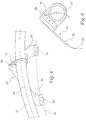
FIG. 5 shows a simplified side view of the arrangement as per FIG. 4.
The gas-turbine engine 10 in accordance with FIG. 1 is an example of a turbomachine where the invention can be used. The following however makes clear that the invention can also be used in other turbomachines. The engine 10 is of conventional design and includes in the flow direction, one behind the other, an air inlet 11, a fan 12 rotating inside a casing, an intermediate-pressure compressor 13, a high-pressure compressor 14, combustion chambers 15, a high-pressure turbine 16, an intermediate-pressure turbine 17 and a low-pressure turbine 18 as well as an exhaust nozzle 19, all of which being arranged about a central engine axis 1.
The intermediate-pressure compressor 13 and the high-pressure compressor 14 each include several stages, of which each has an arrangement extending in the circumferential direction of fixed and stationary guide vanes 20, generally referred to as stator vanes and projecting radially inwards from the engine casing 21 in an annular flow duct through the compressors 13, 14. The compressors furthermore have an arrangement of compressor rotor blades 22 which project radially outwards from a rotatable drum or disk 26 linked to hubs 27 of the high-pressure turbine 16 or the intermediate-pressure turbine 17, respectively.
The turbine sections 16, 17, 18 have similar stages, including an arrangement of fixed stator vanes 23 projecting radially inwards from the casing 21 into the annular flow duct through the turbines 16, 17, 18, and a subsequent arrangement of turbine blades 24 projecting outwards from a rotatable hub 27. The compressor drum or compressor disk 26 and the blades 22 arranged thereon, as well as the turbine rotor hub 27 and the turbine rotor blades 24 arranged thereon rotate about the engine axis 1 during operation.
Reference numeral 28 designates an exhaust cone.
Furthermore, the gas-turbine engine has an inflow region 29 (annular lip), which is part of the engine cowling (nacelle) 30.
As is known from the state of the art, an annular tube element 31 is located next to the inflow region 29 inside the double-walled engine cowling 30, said tube element having outlet openings for passing hot air, that is introduced to it, substantially to the inner wall of the inflow region 29, in order to de-ice it.
FIGS. 2 to 4 show on the one hand the fastening element in accordance with the invention and on the other hand its assignment and use to an annular tube element (“piccolo tube”) for de-icing of the inflow region 29.
In detail, FIG. 4 shows that the fastening element 32 has two struts 33 and 34 designed as sheet-metal bending parts. Hence, the struts 33 and 34 are relatively long, when compared with their thickness and width, so that they can easily deform elastically in one direction. First end areas 35 are connected to the supporting structure of the engine cowling 30, for example to a wall 40. The connection is made by rivets or bolts, for example. The two struts 33 and 34 are arranged at an angle to one another, and the first end areas 35, spacedly arranged to one another, are provided on a circular path 38 which is arranged concentrically to a central axis 39 of the tube element 31.
As FIGS. 2 and 3 show, several fastening elements 32 in accordance with the invention are provided on the circumference of the tube element 31.
The respective second end areas 36 of the struts 33 and 34 are angled and connected to each other, for example likewise using rivets or bolts. The second end areas 36 support a carrier element 37 which is arranged in a plane vertical to the central axis 39 of the tube element 31. The struts 33 and 34 thus form with their second end areas 36 and the carrier element 37 a three-dimensional lattice structure. The second end areas 36 are, as shown in FIGS. 4 and 5, bent round to the central parts of the two struts 33 and 34. The transition between the respective first end areas 35 and the struts 33 and 34 is also provided with a radius. The result is an overall design of high strength which permits elastic deformations.
FIG. 5 shows by the two arrows elastic deformations of the tube element 31 due to thermal stresses (expansion or contraction). The struts 33 and 34 can deform elastically here, so that no internal material stresses occur which could lead to a fracture. Vibrations or movements along the central axis 39 can be withstood in the area of the second end areas 36, as these are elastically deformable together with the carrier element 37 and absorb the resultant stresses.
The fastening element in accordance with the invention is thus distinguished by a simple structure and a simple design method which can be exactly predetermined by suitable dimensioning and material selection. The wear is minimal in comparison with the state of the art, so that a far longer service life is achieved. There is a considerable cost saving thanks to the lower assembly effort and to the low number of parts. In addition, there is an advantage with regard to weight reduction.
LIST OF REFERENCE NUMERALS
1 Engine axis
10 Gas-turbine engine
11 Air inlet/inflow region
12 Fan rotating inside the casing
13 Intermediate-pressure compressor
14 High-pressure compressor
15 Combustion chambers
16 High-pressure turbine
18 Intermediate-pressure turbine
18 Low-pressure turbine
19 Exhaust nozzle
20 Guide vanes
21 Engine casing
22 Compressor rotor blades
23 Stator vanes
24 Turbine blades
26 Compressor drum or disk
27 Turbine rotor hub
28 Exhaust cone
29 Inflow region/annular lip
30 Engine cowling (nacelle)
31 Tube element
32 Fastening element
33 Strut
34 Strut
35 First end area
36 Second end area
37 Carrier element
38 Circular path
39 Central axis
40 Wall

Claims (20)

What is claimed is:
1. A de-icing device of an aircraft gas-turbine engine with an engine cowling enclosing at least one inflow region, with the engine cowling having a double-walled design, comprising:
at least one annular tube element extending in a circumferential direction and including outlet openings for passing hot air to an inflow region of the gas turbine engine, in order to de-ice the inflow region;
a plurality of fastening elements mounting the tube element to the engine cowling in the circumferential direction;
each fastening element including two struts, each strut including a first end area for mounting to the engine cowling and a second end area connected to the tube element, wherein the two first end areas are spaced apart from one another in the circumferential direction along a central axis of the tube element, and the two second end areas are connected to each other, such that the two struts form an angle to each other with respect to the central axis of the tube element; each fastening element thereby providing relative movability of the tube element with respect to the engine cowling.
2. The de-icing device in accordance with claim 1, wherein the first end areas are provided on a circular path which is arranged concentrically to the central axis of the tube element.
3. The de-icing device in accordance with claim 2, and further comprising a carrier element connecting the second end areas to each other and to the tube element.
4. The de-icing device in accordance with claim 3, wherein the tube element is elastically connected to the carrier element.
5. The de-icing device in accordance with claim 4, wherein the carrier element is arranged in a plane vertical to the central axis of the tube element.
6. The de-icing device in accordance with claim 5, wherein the two struts are in a form of flat sheet-metal strips.
7. The de-icing device in accordance with claim 3, wherein the tube element is fixedly connected to the carrier element.
8. The de-icing device in accordance with claim 3, wherein the two struts provide a cantilever mounting of each fastening element with respect to the engine cowling.
9. The de-icing device in accordance with claim 2, wherein the two struts provide a cantilever mounting of each fastening element with respect to the engine cowling.
10. The de-icing device in accordance with claim 7, wherein the carrier element is arranged in a plane vertical to the central axis of the tube element.
11. The de-icing device in accordance with claim 10, wherein the two struts are elastically bendable.
12. The de-icing device in accordance with claim 1, and further comprising a carrier element connecting the second end areas to each other and to the tube element.
13. The de-icing device in accordance with claim 12, wherein the tube element is fixedly connected to the carrier element.
14. The de-icing device in accordance with claim 13, wherein the carrier element is arranged in a plane vertical to the central axis of the tube element.
15. The de-icing device in accordance with claim 14, wherein the two struts are elastically bendable.
16. The de-icing device in accordance with claim 12, wherein the tube element is elastically connected to the carrier element.
17. The de-icing device in accordance with claim 16, wherein the carrier element is arranged in a plane vertical to the central axis of the tube element.
18. The de-icing device in accordance with claim 17, wherein the two struts are in a form of flat sheet-metal strips.
19. The de-icing device in accordance with claim 1, wherein the two struts are elastically bendable.
20. The de-icing device in accordance with claim 1, wherein the two struts provide a cantilever mounting of each fastening element with respect to the engine cowling.
US13/739,772 2012-01-18 2013-01-11 Fastening element and de-icing device of an aircraft gas-turbine engine Active 2034-12-25 US9255523B2 (en)

Applications Claiming Priority (3)

Application Number Priority Date Filing Date Title
DE102012000890A DE102012000890A1 (en) 2012-01-18 2012-01-18 Fastening element and deicing device of an aircraft gas turbine engine
DE102012000890 2012-01-18
DE102012000890.2 2012-01-18

Publications (2)

Publication Number Publication Date
US20130180227A1 US20130180227A1 (en) 2013-07-18
US9255523B2 true US9255523B2 (en) 2016-02-09

Family

ID=47594479

Family Applications (1)

Application Number Title Priority Date Filing Date
US13/739,772 Active 2034-12-25 US9255523B2 (en) 2012-01-18 2013-01-11 Fastening element and de-icing device of an aircraft gas-turbine engine

Country Status (3)

Country Link
US (1) US9255523B2 (en)
EP (1) EP2617979B1 (en)
DE (1) DE102012000890A1 (en)

Cited By (3)

* Cited by examiner, † Cited by third party
Publication number Priority date Publication date Assignee Title
US10995698B2 (en) 2016-09-07 2021-05-04 Rolls-Royce Deutschland Ltd & Co Kg Mixer assembly group for a turbofan engine
US11408341B2 (en) 2018-11-05 2022-08-09 Rohr, Inc. Anti-icing system for an aircraft nacelle
US11708166B2 (en) 2020-04-07 2023-07-25 Rohr, Inc. Aircraft anti-icing system

Families Citing this family (5)

* Cited by examiner, † Cited by third party
Publication number Priority date Publication date Assignee Title
CN104929778B (en) * 2014-03-18 2017-08-25 中国航发商用航空发动机有限责任公司 Engine inlets anti-icing system
BE1023289B1 (en) * 2015-07-17 2017-01-24 Safran Aero Boosters S.A. AXIAL TURBOMACHINE LOW PRESSURE COMPRESSOR SEPARATION SPOUT WITH ANNULAR DEFROST CONDUIT
DE102016120682A1 (en) 2016-10-28 2018-05-03 Rolls-Royce Deutschland Ltd & Co Kg Aircraft bleed air system and method for providing bleed air in an aircraft engine
FR3092616B1 (en) * 2019-02-13 2022-06-24 Safran Aircraft Engines DEVICE FOR FIXING AND MAINTAINING AT LEAST ONE PIPE ON A TURBOMACHINE ELEMENT
FR3096080B1 (en) * 2019-05-13 2021-05-14 Safran Aircraft Engines Turbomachine comprising a system for defrosting the upstream cone, and associated method.

Citations (7)

* Cited by examiner, † Cited by third party
Publication number Priority date Publication date Assignee Title
US3194590A (en) * 1963-06-24 1965-07-13 Heath Tecna Plastics Inc Combination pipe hanger and coupling
US3284037A (en) 1964-11-18 1966-11-08 Muller Franz Pipe suspension means
DE3936198A1 (en) 1988-11-02 1990-05-17 Raimund Hoellein Carolinenhuet Suspended hanger brackets for fixing service pipes to bridges - have facilities for each horizontal and vertical adjustment to suit alignment
WO1994018072A1 (en) 1993-02-09 1994-08-18 Grumman Aerospace Corporation Strain isolator assembly
US6079670A (en) 1997-12-12 2000-06-27 Aerospatiale Societe Nationale Industrielle Hot air diffuser for a jet engine air inlet cowl with de-icing circuit
US20090152401A1 (en) * 2007-12-12 2009-06-18 Spirit Aerosystems, Inc. Nacelle inlet thermal anti-icing spray duct support system
US20100242428A1 (en) 2007-10-08 2010-09-30 Aircelle Air intake structure to be mounted upstream of a nacelle middle structure for aircraft engine, and nacelle equipped with such air intake structure

Patent Citations (7)

* Cited by examiner, † Cited by third party
Publication number Priority date Publication date Assignee Title
US3194590A (en) * 1963-06-24 1965-07-13 Heath Tecna Plastics Inc Combination pipe hanger and coupling
US3284037A (en) 1964-11-18 1966-11-08 Muller Franz Pipe suspension means
DE3936198A1 (en) 1988-11-02 1990-05-17 Raimund Hoellein Carolinenhuet Suspended hanger brackets for fixing service pipes to bridges - have facilities for each horizontal and vertical adjustment to suit alignment
WO1994018072A1 (en) 1993-02-09 1994-08-18 Grumman Aerospace Corporation Strain isolator assembly
US6079670A (en) 1997-12-12 2000-06-27 Aerospatiale Societe Nationale Industrielle Hot air diffuser for a jet engine air inlet cowl with de-icing circuit
US20100242428A1 (en) 2007-10-08 2010-09-30 Aircelle Air intake structure to be mounted upstream of a nacelle middle structure for aircraft engine, and nacelle equipped with such air intake structure
US20090152401A1 (en) * 2007-12-12 2009-06-18 Spirit Aerosystems, Inc. Nacelle inlet thermal anti-icing spray duct support system

Non-Patent Citations (2)

* Cited by examiner, † Cited by third party
Title
European Search Report dated Nov. 17, 2014 for counterpart European Patent Application No. 13000192.8.
German Search Report dated Nov. 5, 2012 from counterpart application.

Cited By (3)

* Cited by examiner, † Cited by third party
Publication number Priority date Publication date Assignee Title
US10995698B2 (en) 2016-09-07 2021-05-04 Rolls-Royce Deutschland Ltd & Co Kg Mixer assembly group for a turbofan engine
US11408341B2 (en) 2018-11-05 2022-08-09 Rohr, Inc. Anti-icing system for an aircraft nacelle
US11708166B2 (en) 2020-04-07 2023-07-25 Rohr, Inc. Aircraft anti-icing system

Also Published As

Publication number Publication date
US20130180227A1 (en) 2013-07-18
EP2617979B1 (en) 2016-06-08
EP2617979A2 (en) 2013-07-24
DE102012000890A1 (en) 2013-07-18
EP2617979A3 (en) 2014-12-17

Similar Documents

Publication Publication Date Title
US9255523B2 (en) Fastening element and de-icing device of an aircraft gas-turbine engine
US11021990B2 (en) Shroud sealing for a gas turbine engine
US8678319B2 (en) De-icing device of an aircraft gas-turbine engine
JP4393797B2 (en) Compressor bleed case
US20180066531A1 (en) Integrated strut and vane arrangements
US9719421B2 (en) Gas-turbine engine with telescope-type air inlet of the engine cowling (nacelle)
US9194253B2 (en) Flexible rear bearing mounting, having an abutment, for a turbine engine
US8870533B2 (en) Assembly for aligning an inner shell of a turbine casing
US20130067930A1 (en) Axial bolting arrangement for mid turbine frame
US10837646B2 (en) Combustion chamber shingle arrangement of a gas turbine
US9863278B2 (en) Air exhaust tube holder in a turbomachine
US8403636B2 (en) Turbine stage in a turbomachine
US9279326B2 (en) Method for balancing and assembling a turbine rotor
US20140069107A1 (en) Turboprop engine with compressor turbine shroud
EP2325438A2 (en) Seal plates for directing airflow through a turbine section of an engine and turbine sections
US8894361B2 (en) Gas turbine compressor inlet with reduced flow distortion
US20150030443A1 (en) Split damped outer shroud for gas turbine engine stator arrays
US20150176413A1 (en) Snubber configurations for turbine rotor blades
EP2447475B1 (en) Airfoil attachement arrangement
RU2648809C2 (en) Air exhaust tube holder in a turbomachine
EP3477047B1 (en) Segmented structural links for coupled disk frequency tuning and corresponding gas turbine engine with such links
WO2017041969A1 (en) Arrangement for a gas turbine
US8840374B2 (en) Adaptor assembly for coupling turbine blades to rotor disks
US9945240B2 (en) Power turbine heat shield architecture
US20130055716A1 (en) Gas-turbine combustion chamber with a holding means of a seal for an attachment

Legal Events

Date Code Title Description
AS Assignment

Owner name: ROLLS-ROYCE DEUTSCHLAND LTD & CO KG, GERMANY

Free format text: ASSIGNMENT OF ASSIGNORS INTEREST;ASSIGNORS:TODOROVIC, PREDRAG;ARAUJO, GUSTAVO;SIGNING DATES FROM 20130414 TO 20130417;REEL/FRAME:030319/0620

STCF Information on status: patent grant

Free format text: PATENTED CASE

MAFP Maintenance fee payment

Free format text: PAYMENT OF MAINTENANCE FEE, 4TH YEAR, LARGE ENTITY (ORIGINAL EVENT CODE: M1551); ENTITY STATUS OF PATENT OWNER: LARGE ENTITY

Year of fee payment: 4

MAFP Maintenance fee payment

Free format text: PAYMENT OF MAINTENANCE FEE, 8TH YEAR, LARGE ENTITY (ORIGINAL EVENT CODE: M1552); ENTITY STATUS OF PATENT OWNER: LARGE ENTITY

Year of fee payment: 8