US9250412B2 - Lens device - Google Patents
Lens device Download PDFInfo
- Publication number
- US9250412B2 US9250412B2 US13/866,517 US201313866517A US9250412B2 US 9250412 B2 US9250412 B2 US 9250412B2 US 201313866517 A US201313866517 A US 201313866517A US 9250412 B2 US9250412 B2 US 9250412B2
- Authority
- US
- United States
- Prior art keywords
- barrel
- adjusting
- movable
- optical axis
- lens
- Prior art date
- Legal status (The legal status is an assumption and is not a legal conclusion. Google has not performed a legal analysis and makes no representation as to the accuracy of the status listed.)
- Expired - Fee Related, expires
Links
Images


Classifications
-
- G—PHYSICS
- G02—OPTICS
- G02B—OPTICAL ELEMENTS, SYSTEMS OR APPARATUS
- G02B7/00—Mountings, adjusting means, or light-tight connections, for optical elements
- G02B7/02—Mountings, adjusting means, or light-tight connections, for optical elements for lenses
- G02B7/022—Mountings, adjusting means, or light-tight connections, for optical elements for lenses lens and mount having complementary engagement means, e.g. screw/thread
-
- G—PHYSICS
- G02—OPTICS
- G02B—OPTICAL ELEMENTS, SYSTEMS OR APPARATUS
- G02B15/00—Optical objectives with means for varying the magnification
- G02B15/14—Optical objectives with means for varying the magnification by axial movement of one or more lenses or groups of lenses relative to the image plane for continuously varying the equivalent focal length of the objective
Definitions
- the invention relates to a lens device, more particularly to a lens device that has an alignment correction unit for adjusting an axis of a lens module.
- a lens device generally has a lens adjustable for correcting the position thereof so as to achieve optimum optical characteristics for the lens device.
- U.S. Pat. No. 7,139,138 discloses a conventional lens device including a lens barrel and a lens mounted in the lens barrel. The lens is movable with respect to an optical axis via a guiding unit disposed between the lens barrel and the lens, or a positioning unit sleeved on the lens so as to adjust a lens axis of the lens relative to the optical axis.
- the lens is only movable in transverse directions with respect to the optical axis, so that the adjustment between the lens axis and the optical axis may not be easily conducted.
- U.S. Pat. No. 7,187,508 discloses another conventional lens device that includes an alignment correction unit for adjusting a lens axis of a lens module.
- the alignment correction unit includes a mounting ring, a module barrel mounted with the lens module, an elastically deformable component clamped between the mounting ring and the module barrel, and four screw fasteners extending through the module barrel into the mounting ring for locking the module barrel to the mounting ring.
- the depths of the threaded engagement of the screw fasteners with the mounting ring can be independently adjusted such that the module barrel can be tilted relative to the mounting ring, and that the lens axis of the lens module can be precisely adjusted.
- the structure of this conventional lens device is relatively complicated, and the operation of the alignment correction unit is relatively inconvenient.
- the object of the present invention is to provide a lens device that may alleviate the abovementioned drawbacks of the prior art.
- a lens device of the present invention comprises a first barrel, a first frame and an adjusting unit.
- the first barrel has an inner surrounding surface that surrounds an optical axis.
- the first frame is coupled rotatably to the first barrel and has an outer surrounding surface that surrounds a first axis.
- the adjusting unit has an adjusting groove that is formed in one of the inner surrounding surface of the first barrel and the outer surrounding surface of the first frame, and that has a plurality of angularly spaced-apart adjusting groove segments. One of the adjusting groove segments extends spirally.
- the adjusting unit further has a plurality of adjusting blocks that are formed on the other one of the inner surrounding surface of the first barrel and the outer surrounding surface of the first frame and that engage respectively and slidably the adjusting grooves.
- the first frame is rotatable relative to the first barrel to adjust the first axis relative to the optical axis.
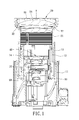
- FIG. 1 is a sectional view of a preferred embodiment of a lens device according to the invention.
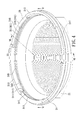
- FIG. 2 is an assembled perspective view of a first barrel and a first frame of the preferred embodiment
- FIG. 3 is an exploded perspective view of the first barrel and the first frame of the preferred embodiment
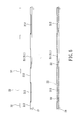
- FIG. 4 is a fragmentary perspective view of the first barrel of the preferred embodiment
- FIG. 5 is a fragmentary sectional view taken along line V-V in FIG. 4 ;
- FIG. 6 is a fragmentary schematic sectional view illustrating how the first frame is coupled to the first barrel.
- FIG. 7 is an enlarged fragmentary sectional view taken along line VII-VII in FIG. 4 .
- the preferred embodiment of a lens device comprises a base barrel 10 , a rotatable barrel 11 , a cam barrel 12 , a first movable barrel 13 , a second movable barrel 14 , a first lens module 20 , an adjusting unit 30 , a second lens module 40 , a third lens module 50 and a focus lens module 60 .
- the base barrel 10 surrounds an optical axis (X).
- the rotatable barrel 11 surrounds rotatably the base barrel 10 .
- the cam barrel 12 is mounted rotatably in the base barrel 10 .
- the first movable barrel 13 is coupled to the base barrel 10 and the cam barrel 12 , is movable relative to the base barrel 10 along the optical axis (X) , and is co-movable with the cam barrel 12 along the optical axis (X) .
- the second movable barrel 14 is coupled to the base barrel 10 and the cam barrel 12 , is movable relative to the base barrel 10 along the optical axis (X) , and is co-movable with the cam barrel 12 along the optical axis (X).
- the first lens module 20 , the second lens module 40 , the third lens module 50 and the focus lens module 60 are disposed on the optical axis (X) and are arranged from front to rear in sequence and in the given order.
- the first lens module 20 is mounted in the first movable barrel 13 .
- the cam barrel 12 is movable to drive movement of the first lens module 20 relative to the first movable barrel 13 along the optical axis (X).
- the second and third lens modules 40 , 50 are mounted in the second movable barrel 14 .
- the cam barrel 12 is movable to drive movement of the second and third lens modules 40 , 50 relative to the second movable barrel 14 along the optical axis (X). Since the way the first, second, third and focus lens modules 20 , 40 , 50 , 60 are moved is known in the art, further details of the same are omitted herein for the sake of brevity.
- the first lens module 20 includes a first barrel 21 , a first frame 22 and a plurality of first lenses 23 .
- the first barrel 21 has an inner surrounding surface 24 that surrounds the optical axis (X), and a rear contact surface 25 that is disposed at a front end of the first barrel 21 , that is connected to the inner surrounding surface 24 and that is formed with a plurality of angularly spaced-apart adhesive grooves 26 .
- the first frame 22 is coupled rotatably to the first barrel 21 , and has an outer surrounding surface 222 that surrounds a first axis 221 , and a front contact surface 223 that is connected transversely to the outer surrounding surface 222 , and that confronts the rear contact surface 25 of the first barrel 21 .
- the adjusting unit 30 has an adjusting groove 31 that is formed in the inner surrounding surface 24 of the first barrel 21 , and that has a plurality of angularly spaced-apart adjusting groove segments.
- One of the adjusting groove segments is configured to extend spirally and is defined as a main adjusting groove segment 311 .
- the remaining of the adjusting groove segments define an imaginary circular surface which is normal to the optical axis (X).
- Each of the remaining of the adjusting groove segments is defined as an auxiliary adjusting groove segment 312 .
- the adjusting unit 30 further has a plurality of adjusting blocks 32 that are formed on the outer surrounding surface 222 of the first frame 22 behind the front contact surface 223 of the first frame 22 , and that engage respectively and slidably the main and auxiliary adjusting groove segments 311 , 312 .
- the adjusting groove 31 is defined cooperatively by an annular rear surface section 241 , a front surface section 242 spaced apart from the rear surface section 241 along the optical axis (X) and disposed between the rear surface section 241 and a front end of the first barrel 21 , and a side surface section 243 interconnecting the rear and front surface sections 241 , 242 .
- the rear surface section 241 has a connecting surface segment 244 and a spirally-extending adjusting surface segment 245 interconnecting opposite ends of the connecting surface segment 244 .
- the adjusting surface segment 245 is disposed behind the imaginary circular surface that is defined by the auxiliary adjusting groove segment 312 .
- the adjusting groove 31 further has a plurality of angularly spaced-apart openings 313 extending through the front surface section 242 and the front end of the first barrel 21 , and dividing the front surface section 242 into a plurality of surface segments that correspond in position to the adjusting groove segments 311 , 312 , respectively.
- one of the surface segments of the front surface section 242 extends spirally and is defined as an adjusting surface segment 246 , and a portion of the adjusting surface segment 245 is configured to correspond in position to the adjusting surface segment 246 and cooperates with the adjusting surface segment 246 to define the main adjusting groove segment 311 .
- a remaining portion of the adjusting surface segment 245 is configured to correspond in position to one of the openings 313 that is adjacent to the main adjusting groove segment 311 .
- the rest of the surface segments of the front surface section 242 define another imaginary circular surface which is normal to the optical axis (X) and each is defined as a connecting surface segment 247 .
- the adjusting surface segment 246 is disposed behind the imaginary circular surface that is defined by the connecting surface segments 247 .
- the portion of the adjusting surface segment 245 corresponding in position to the adjusting surface segment 246 is a stepped surface segment 248 .
- the first frame 22 is moved relative to the first barrel 21 to pass the adjusting blocks 32 respectively through the openings 313 and into the adjusting groove 31 .
- the first frame 22 is rotated relative to the first barrel 21 so that the adjusting blocks 32 are moved into the main and the auxiliary adjusting groove segments 311 , 312 , respectively.
- one of the adjusting blocks 32 that engages the main adjusting groove segment 311 is moved to slide spirally due to the spirally-extending stepped configuration of the main adjusting groove segment 311 during further rotation of the first frame 22 , thereby tilting the first frame 22 and the first lenses 23 relative to the first barrel 21 . Therefore, the first axis 221 can be adjusted to tilt relative to the optical axis (X) (see FIG. 7 ) so as to achieve optimum optical characteristics for the lens device of this invention.
- the structure of the adjusting unit 30 is relatively simple, and the adjustment of the first axis 221 can be easily and precisely conducted by rotating the first frame 22 relative to the first barrel 21 . Moreover, during the rotation of the first frame 22 for tilting the first axis 221 , the orientation of the first axis 221 is also changed, so that the lens device of this invention has a greater adjustment flexibility than the prior art.
Landscapes
- Physics & Mathematics (AREA)
- General Physics & Mathematics (AREA)
- Optics & Photonics (AREA)
- Lens Barrels (AREA)
Abstract
Description
Claims (9)
Applications Claiming Priority (3)
| Application Number | Priority Date | Filing Date | Title |
|---|---|---|---|
| TW101114741A | 2012-04-25 | ||
| TW101114741 | 2012-04-25 | ||
| TW101114741A TWI485458B (en) | 2012-04-25 | 2012-04-25 | Tiltable lens |
Publications (2)
| Publication Number | Publication Date |
|---|---|
| US20130286492A1 US20130286492A1 (en) | 2013-10-31 |
| US9250412B2 true US9250412B2 (en) | 2016-02-02 |
Family
ID=49477055
Family Applications (1)
| Application Number | Title | Priority Date | Filing Date |
|---|---|---|---|
| US13/866,517 Expired - Fee Related US9250412B2 (en) | 2012-04-25 | 2013-04-19 | Lens device |
Country Status (2)
| Country | Link |
|---|---|
| US (1) | US9250412B2 (en) |
| TW (1) | TWI485458B (en) |
Citations (1)
| Publication number | Priority date | Publication date | Assignee | Title |
|---|---|---|---|---|
| US20110102921A1 (en) * | 2009-10-30 | 2011-05-05 | Sato Masumi David | Lens device |
Family Cites Families (4)
| Publication number | Priority date | Publication date | Assignee | Title |
|---|---|---|---|---|
| WO2008139723A1 (en) * | 2007-05-07 | 2008-11-20 | Panasonic Corporation | Conversion lens and camera system using same |
| CN101359079B (en) * | 2007-07-30 | 2010-04-14 | 佛山普立华科技有限公司 | Lens module |
| TWM341234U (en) * | 2008-02-19 | 2008-09-21 | Limit Optics Co Ltd | Lens module having lens set with variable curvature |
| TWM365487U (en) * | 2009-06-01 | 2009-09-21 | Baso Prec Optics Ltd | Diaphragms adjusting apparatus for camera lens of projector |
-
2012
- 2012-04-25 TW TW101114741A patent/TWI485458B/en not_active IP Right Cessation
-
2013
- 2013-04-19 US US13/866,517 patent/US9250412B2/en not_active Expired - Fee Related
Patent Citations (1)
| Publication number | Priority date | Publication date | Assignee | Title |
|---|---|---|---|---|
| US20110102921A1 (en) * | 2009-10-30 | 2011-05-05 | Sato Masumi David | Lens device |
Also Published As
| Publication number | Publication date |
|---|---|
| TW201344276A (en) | 2013-11-01 |
| TWI485458B (en) | 2015-05-21 |
| US20130286492A1 (en) | 2013-10-31 |
Similar Documents
| Publication | Publication Date | Title |
|---|---|---|
| US20050286250A1 (en) | Spotlight | |
| US7423815B2 (en) | Adjustable lens device | |
| JP3915020B2 (en) | Lens barrel structure of zoom lens device | |
| US20160178989A1 (en) | Lens barrel and optical apparatus | |
| US11822228B2 (en) | Imaging device | |
| JP5273063B2 (en) | Optical apparatus and optical apparatus | |
| US20080030863A1 (en) | Lens device | |
| JPWO2017115465A1 (en) | Lens barrel and camera equipped with the same | |
| US11300753B2 (en) | Lens apparatus and imaging apparatus including the same | |
| US9250412B2 (en) | Lens device | |
| US10495841B2 (en) | Lens barrel and imaging device | |
| JP4910138B2 (en) | Lens barrel with focus adjustment mechanism | |
| CN103460100B (en) | Lens device | |
| JP5883260B2 (en) | Lens barrel and imaging device | |
| WO2018135453A1 (en) | Imaging device | |
| US9121997B2 (en) | Lens barrel | |
| US11471994B2 (en) | Lens blocker | |
| KR20100020216A (en) | Barrel of optical system | |
| JP2016184102A (en) | Zoom lens device and control method for the same | |
| CN110927916B (en) | Adjusting device for rear intercept of lens and camera | |
| JP2011061301A (en) | Imaging apparatus | |
| JP2018180357A (en) | Lens barrel | |
| JP5538136B2 (en) | Lens barrel with eccentricity adjustment mechanism | |
| TW201537214A (en) | Optical device | |
| WO2012128202A1 (en) | Lens device |
Legal Events
| Date | Code | Title | Description |
|---|---|---|---|
| AS | Assignment |
Owner name: SINTAI OPTICAL (SHENZHEN) CO., LTD., CHINA Free format text: ASSIGNMENT OF ASSIGNORS INTEREST;ASSIGNOR:CHEN, TSUNG-TSE;REEL/FRAME:030253/0869 Effective date: 20130412 Owner name: ASIA OPTICAL INTERNATIONAL, LTD.., VIRGIN ISLANDS, Free format text: ASSIGNMENT OF ASSIGNORS INTEREST;ASSIGNOR:CHEN, TSUNG-TSE;REEL/FRAME:030253/0869 Effective date: 20130412 |
|
| ZAAA | Notice of allowance and fees due |
Free format text: ORIGINAL CODE: NOA |
|
| ZAAB | Notice of allowance mailed |
Free format text: ORIGINAL CODE: MN/=. |
|
| STCF | Information on status: patent grant |
Free format text: PATENTED CASE |
|
| MAFP | Maintenance fee payment |
Free format text: PAYMENT OF MAINTENANCE FEE, 4TH YEAR, LARGE ENTITY (ORIGINAL EVENT CODE: M1551); ENTITY STATUS OF PATENT OWNER: LARGE ENTITY Year of fee payment: 4 |
|
| FEPP | Fee payment procedure |
Free format text: MAINTENANCE FEE REMINDER MAILED (ORIGINAL EVENT CODE: REM.); ENTITY STATUS OF PATENT OWNER: LARGE ENTITY |
|
| LAPS | Lapse for failure to pay maintenance fees |
Free format text: PATENT EXPIRED FOR FAILURE TO PAY MAINTENANCE FEES (ORIGINAL EVENT CODE: EXP.); ENTITY STATUS OF PATENT OWNER: LARGE ENTITY |
|
| STCH | Information on status: patent discontinuation |
Free format text: PATENT EXPIRED DUE TO NONPAYMENT OF MAINTENANCE FEES UNDER 37 CFR 1.362 |
|
| FP | Lapsed due to failure to pay maintenance fee |
Effective date: 20240202 |