US9245546B1 - Contamination mitigation cap for a hard disk drive actuator pivot assembly - Google Patents
Contamination mitigation cap for a hard disk drive actuator pivot assembly Download PDFInfo
- Publication number
- US9245546B1 US9245546B1 US14/642,450 US201514642450A US9245546B1 US 9245546 B1 US9245546 B1 US 9245546B1 US 201514642450 A US201514642450 A US 201514642450A US 9245546 B1 US9245546 B1 US 9245546B1
- Authority
- US
- United States
- Prior art keywords
- cap
- contamination
- mitigation
- actuator
- contamination mitigation
- Prior art date
- Legal status (The legal status is an assumption and is not a legal conclusion. Google has not performed a legal analysis and makes no representation as to the accuracy of the status listed.)
- Active
Links
Images


Classifications
-
- G—PHYSICS
- G11—INFORMATION STORAGE
- G11B—INFORMATION STORAGE BASED ON RELATIVE MOVEMENT BETWEEN RECORD CARRIER AND TRANSDUCER
- G11B5/00—Recording by magnetisation or demagnetisation of a record carrier; Reproducing by magnetic means; Record carriers therefor
- G11B5/127—Structure or manufacture of heads, e.g. inductive
- G11B5/33—Structure or manufacture of flux-sensitive heads, i.e. for reproduction only; Combination of such heads with means for recording or erasing only
- G11B5/39—Structure or manufacture of flux-sensitive heads, i.e. for reproduction only; Combination of such heads with means for recording or erasing only using magneto-resistive devices or effects
-
- G—PHYSICS
- G11—INFORMATION STORAGE
- G11B—INFORMATION STORAGE BASED ON RELATIVE MOVEMENT BETWEEN RECORD CARRIER AND TRANSDUCER
- G11B5/00—Recording by magnetisation or demagnetisation of a record carrier; Reproducing by magnetic means; Record carriers therefor
- G11B5/48—Disposition or mounting of heads or head supports relative to record carriers ; arrangements of heads, e.g. for scanning the record carrier to increase the relative speed
- G11B5/54—Disposition or mounting of heads or head supports relative to record carriers ; arrangements of heads, e.g. for scanning the record carrier to increase the relative speed with provision for moving the head into or out of its operative position or across tracks
- G11B5/55—Track change, selection or acquisition by displacement of the head
- G11B5/5521—Track change, selection or acquisition by displacement of the head across disk tracks
-
- F—MECHANICAL ENGINEERING; LIGHTING; HEATING; WEAPONS; BLASTING
- F16—ENGINEERING ELEMENTS AND UNITS; GENERAL MEASURES FOR PRODUCING AND MAINTAINING EFFECTIVE FUNCTIONING OF MACHINES OR INSTALLATIONS; THERMAL INSULATION IN GENERAL
- F16C—SHAFTS; FLEXIBLE SHAFTS; ELEMENTS OR CRANKSHAFT MECHANISMS; ROTARY BODIES OTHER THAN GEARING ELEMENTS; BEARINGS
- F16C35/00—Rigid support of bearing units; Housings, e.g. caps, covers
-
- F—MECHANICAL ENGINEERING; LIGHTING; HEATING; WEAPONS; BLASTING
- F16—ENGINEERING ELEMENTS AND UNITS; GENERAL MEASURES FOR PRODUCING AND MAINTAINING EFFECTIVE FUNCTIONING OF MACHINES OR INSTALLATIONS; THERMAL INSULATION IN GENERAL
- F16C—SHAFTS; FLEXIBLE SHAFTS; ELEMENTS OR CRANKSHAFT MECHANISMS; ROTARY BODIES OTHER THAN GEARING ELEMENTS; BEARINGS
- F16C2370/00—Apparatus relating to physics, e.g. instruments
- F16C2370/12—Hard disk drives or the like
-
- G—PHYSICS
- G11—INFORMATION STORAGE
- G11B—INFORMATION STORAGE BASED ON RELATIVE MOVEMENT BETWEEN RECORD CARRIER AND TRANSDUCER
- G11B5/00—Recording by magnetisation or demagnetisation of a record carrier; Reproducing by magnetic means; Record carriers therefor
- G11B5/48—Disposition or mounting of heads or head supports relative to record carriers ; arrangements of heads, e.g. for scanning the record carrier to increase the relative speed
- G11B5/4806—Disposition or mounting of heads or head supports relative to record carriers ; arrangements of heads, e.g. for scanning the record carrier to increase the relative speed specially adapted for disk drive assemblies, e.g. assembly prior to operation, hard or flexible disk drives
- G11B5/4813—Mounting or aligning of arm assemblies, e.g. actuator arm supported by bearings, multiple arm assemblies, arm stacks or multiple heads on single arm
Definitions
- Embodiments of the invention may relate generally to hard disk drives and more particularly to a contamination mitigation cap for an actuator pivot assembly.
- a hard-disk drive is a non-volatile storage device that is housed in a protective enclosure and stores digitally encoded data on one or more circular disk having magnetic surfaces.
- each magnetic-recording disk is rapidly rotated by a spindle system.
- Data is read from and written to a magnetic-recording disk using a read/write head that is positioned over a specific location of a disk by an actuator.
- a read/write head uses a magnetic field to read data from and write data to the surface of a magnetic-recording disk.
- a write head makes use of the electricity flowing through a coil, which produces a magnetic field. Electrical pulses are sent to the write head, with different patterns of positive and negative currents. The current in the coil of the write head induces a magnetic field across the gap between the head and the magnetic disk, which in turn magnetizes a small area on the recording medium.
- the actuator rotates to move across portions of the disk
- the actuator includes a pivot assembly.
- the pivot assembly typically includes a pivot bearing assembly, such as a ball-bearing assembly.
- the pivot bearing assembly typically includes a lubricant, such as a hydrocarbon-based oil.
- a lubricant such as a hydrocarbon-based oil.
- Such a bearing assembly is typically not completely sealed and, therefore, some of the lubricant is known to exit the bearing assembly and can migrate to the head-disk interface (HDI) which can lead to read and/or write errors.
- HDI head-disk interface
- Embodiments of the invention are directed toward an actuator contamination mitigation cap, a hard disk drive and corresponding actuator pivot assembly employing such a contamination mitigation cap, and a method for assembling an actuator pivot assembly utilizing such a contamination mitigation cap, where the contamination mitigation cap is affixed to the rotatable carriage of the actuator assembly and, in conjunction with a bearing hub cap, forms a labyrinth seal for retaining pivot bearing contamination. Consequently, the risk of such contamination migrating to the head-disk interface and causing read and/or write problems is mitigated.
- Embodiments include various shapes of the contamination mitigation cap, such as a flat ring, an S-section ring, and an L-section ring. Additionally, the contamination mitigation cap may include a constituent pressure sensitive adhesive for bonding the cap to the carriage. For a non-limiting example, an actuator pivot assembly in which the type of contamination mitigation cap described herein is utilized is especially useful in the context of sleeveless pivot bearing assemblies.
- Embodiments discussed in the Summary of Embodiments section are not meant to suggest, describe, or teach all the embodiments discussed herein.
- embodiments of the invention may contain additional or different features than those discussed in this section.
- FIG. 1 is a plan view illustrating a hard disk drive (HDD), according to an embodiment
- FIG. 2 is a cross-sectional side view illustrating an HDD actuator pivot assembly, according to an embodiment
- FIG. 3A is a cross-sectional side view illustrating an HDD actuator pivot assembly, according to an embodiment
- FIG. 3B is a perspective view illustrating a contamination mitigation cap, according to an embodiment
- FIG. 4A is a cross-sectional side view illustrating an HDD actuator pivot assembly, according to an embodiment
- FIG. 4B is a perspective view illustrating a contamination mitigation cap, according to an embodiment
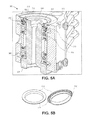
- FIG. 5A is a cross-sectional side view illustrating an HDD actuator pivot assembly, according to an embodiment
- FIG. 5B is a perspective view illustrating a contamination mitigation cap, according to an embodiment.
- FIG. 6 is a flow diagram illustrating a method for assembling an HDD actuator pivot assembly, according to an embodiment.
- Embodiments may be used for mitigating contamination from an actuator in a hard disk drive (HDD) storage device.
- HDD hard disk drive
- FIG. 1 a plan view illustrating an HDD 100 is shown in FIG. 1 to illustrate an exemplary operating environment.
- FIG. 1 illustrates the functional arrangement of components of the HDD 100 including a slider 110 b that includes a magnetic-reading/recording head 110 a .
- slider 110 b and head 110 a may be referred to as a head slider.
- the HDD 100 includes at least one head gimbal assembly (HGA) 110 including the head slider, a lead suspension 110 c attached to the head slider typically via a flexure, and a load beam 110 d attached to the lead suspension 110 c .
- the HDD 100 also includes at least one magnetic-recording medium 120 rotatably mounted on a spindle 124 and a drive motor (not visible) attached to the spindle 124 for rotating the medium 120 .
- HGA head gimbal assembly
- the head 110 a includes a write element and a read element for respectively writing and reading information stored on the medium 120 of the HDD 100 .
- the medium 120 or a plurality of disk media may be affixed to the spindle 124 with a disk clamp 128 .
- the HDD 100 further includes an arm 132 attached to the HGA 110 , a carriage 134 , a voice-coil motor (VCM) that includes an armature 136 including a voice coil 140 attached to the carriage 134 and a stator 144 including a voice-coil magnet (not visible).
- the armature 136 of the VCM is attached to the carriage 134 and is configured to move the arm 132 and the HGA 110 , to access portions of the medium 120 , being mounted on a pivot-shaft 148 with an interposed pivot bearing assembly 152 .
- the carriage 134 is called an “E-block,” or comb, because the carriage is arranged to carry a ganged array of arms that gives it the appearance of a comb.
- An assembly comprising a head gimbal assembly (e.g., HGA 110 ) including a flexure to which the head slider is coupled, an actuator arm (e.g., arm 132 ) and/or load beam to which the flexure is coupled, and an actuator (e.g., the VCM) to which the actuator arm is coupled, may be collectively referred to as a head stack assembly (HSA).
- HSA head stack assembly
- An HSA may, however, include more or fewer components than those described.
- an HSA may refer to an assembly that further includes electrical interconnection components.
- an HSA is the assembly configured to move the head slider to access portions of the medium 120 for read and write operations.
- electrical signals comprising a write signal to and a read signal from the head 110 a
- a flexible interconnect cable 156 (“flex cable”).
- Interconnection between the flex cable 156 and the head 110 a may be provided by an arm-electronics (AE) module 160 , which may have an on-board pre-amplifier for the read signal, as well as other read-channel and write-channel electronic components.
- the AE 160 may be attached to the carriage 134 as shown.
- the flex cable 156 is coupled to an electrical-connector block 164 , which provides electrical communication through electrical feedthroughs provided by an HDD housing 168 .
- the HDD housing 168 also referred to as a base, in conjunction with an HDD cover provides a sealed, protective enclosure for the information storage components of the HDD 100 .
- DSP digital-signal processor
- the spinning medium 120 creates a cushion of air that acts as an air-bearing on which the air-bearing surface (ABS) of the slider 110 b rides so that the slider 110 b flies above the surface of the medium 120 without making contact with a thin magnetic-recording layer in which information is recorded.
- ABS air-bearing surface
- the electrical signal provided to the voice coil 140 of the VCM enables the head 110 a of the HGA 110 to access a track 176 on which information is recorded.
- the armature 136 of the VCM swings through an arc 180 , which enables the head 110 a of the HGA 110 to access various tracks on the medium 120 .
- Information is stored on the medium 120 in a plurality of radially nested tracks arranged in sectors on the medium 120 , such as sector 184 .
- each track is composed of a plurality of sectored track portions (or “track sector”), for example, sectored track portion 188 .
- Each sectored track portion 188 may be composed of recorded data and a header containing a servo-burst-signal pattern, for example, an ABCD-servo-burst-signal pattern, which is information that identifies the track 176 , and error correction code information.
- a servo-burst-signal pattern for example, an ABCD-servo-burst-signal pattern, which is information that identifies the track 176 , and error correction code information.
- the read element of the head 110 a of the HGA 110 reads the servo-burst-signal pattern which provides a position-error-signal (PES) to the servo electronics, which controls the electrical signal provided to the voice coil 140 of the VCM, enabling the head 110 a to follow the track 176 .
- PES position-error-signal
- the head 110 a Upon finding the track 176 and identifying a particular sectored track portion 188 , the head 110 a either reads data from the track 176 or writes data to the track 176 depending on instructions received by the disk controller from an external agent, for example, a microprocessor of a computer system.
- an external agent for example, a microprocessor of a computer system.
- An HDD's electronic architecture comprises numerous electronic components for performing their respective functions for operation of an HDD, such as a hard disk controller (“HDC”), an interface controller, an arm electronics module, a data channel, a motor driver, a servo processor, buffer memory, etc. Two or more of such components may be combined on a single integrated circuit board referred to as a “system on a chip” (“SOC”). Several, if not all, of such electronic components are typically arranged on a printed circuit board that is coupled to the bottom side of an HDD, such as to HDD housing 168 .
- HDC hard disk controller
- SOC system on a chip
- references herein to a hard disk drive may encompass a data storage device that is at times referred to as a “hybrid drive”.
- a hybrid drive refers generally to a storage device having functionality of both a traditional HDD (see, e.g., HDD 100 ) combined with solid-state storage device (SSD) using non-volatile memory, such as flash or other solid-state (e.g., integrated circuits) memory, which is electrically erasable and programmable.
- the solid-state portion of a hybrid drive may include its own corresponding controller functionality, which may be integrated into a single controller along with the HDD functionality.
- a hybrid drive may be architected and configured to operate and to utilize the solid-state portion in a number of ways, such as, for non-limiting examples, by using the solid-state memory as cache memory, for storing frequently-accessed data, for storing I/O intensive data, and the like. Further, a hybrid drive may be architected and configured essentially as two storage devices in a single enclosure, i.e., a traditional HDD and an SSD, with either one or multiple interfaces for host connection.
- the pivot bearing assembly typically includes a lubricant and because such a bearing assembly is typically not completely sealed, some of the lubricant is known to exit the bearing assembly and can migrate to the head-disk interface (HDI) which can lead to read and/or write errors.
- HDI head-disk interface
- barrier films at critical locations along the migration path, which act as anti-wetting agents and inhibit the transport of lubricants.
- barrier films may also be viable, i.e., by containing the lubricant at the pivot bearing assembly.
- FIG. 2 is a cross-sectional side view illustrating an HDD actuator pivot assembly, according to an embodiment.
- Actuator pivot assembly 200 comprises an actuator comb comprising a carriage 202 having a bore 204 therethrough.
- Actuator pivot assembly 200 further comprises a sleeveless pivot bearing assembly 206 disposed within the carriage bore 204 and a shaft 208 to which a circular ring-shaped hub cap 210 is attached.
- the hub cap 210 provides some degree of resistance to the outflow of lubricant (e.g., oil) from the pivot bearing.
- lubricant e.g., oil
- pivot bearing assembly 206 is a sleeveless assembly (at least in part due to space constraints and optimizations within an HDD), any approach involving the creation of a labyrinth seal in association with the hub cap 210 and such a bearing sleeve is not achievable.
- FIG. 3A is a cross-sectional side view illustrating an HDD actuator pivot assembly, according to an embodiment.
- Actuator pivot assembly 300 comprises a rotatable actuator comb comprising a carriage 302 having a bore 304 therethrough.
- Actuator pivot assembly 300 further comprises a pivot bearing assembly 306 (e.g., sleeveless) disposed within the carriage bore 304 and a shaft 308 to which a circular ring-shaped lower hub cap 310 is fixed.
- a typical pivot bearing assembly is composed of the shaft 308 , a spacer 307 , lower bearing 309 a and upper bearing 309 B, and the lower hub cap 310 .
- the actuator pivot assembly 300 comprises a contamination mitigation cap 312 bonded to the rotatable carriage 302 .
- the contamination mitigation cap 312 is configured, in positional relation with the lower hub cap 310 , to form a labyrinth for retaining contamination (e.g., lubricant, oil) from the pivot bearing assembly 306 .
- contamination e.g., lubricant, oil
- bearing oil would have to travel along a circuitous labyrinth 313 path in order to outflow from the actuator pivot assembly 300 and, therefore, is now less likely to be able to migrate over time and operational use, to the head-disk interface where it could otherwise cause significant operational problems.
- the contamination mitigation cap 312 is positioned above the lower hub cap 310 , to form the labyrinth.
- the contamination mitigation cap 312 is bonded to the carriage 302 rather than to any part of the pivot bearing 306 , such as to a pivot bearing sleeve which is not present in the design of a sleeveless bearing such as pivot bearing assembly 306 .
- a sleeveless pivot bearing can be beneficial in an HDD design as it consumes less internal space and provides for reduced cost and reduced inertia, which may lead to better actuator performance and thus better HDD performance than an HDD design in which a sleeved bearing is used.
- the pivot bearing assembly used in an actuator pivot assembly may be a pivot bearing assembly comprising an outer sleeve, i.e., a sleeved pivot bearing assembly.
- FIG. 3B is a perspective view illustrating a contamination mitigation cap 312 , according to an embodiment.
- Contamination mitigation cap 312 is composed of a flat metal ring portion 314 , and a pressure sensitive adhesive (PSA) 316 around the outer edge of the contamination mitigation cap 312 for bonding the contamination mitigation cap 312 to a portion, i.e., a seat, of the carriage 302 .
- PSA pressure sensitive adhesive
- Use of a PSA may be beneficial in providing for removal of the contamination mitigation cap 312 , for example, for reworking a unit. Further, use of a PSA does not require curing and cleaning, such as with some other bonding adhesives.
- the metal of flat metal ring portion 314 is a stainless steel material.
- One approach to the formation of the contamination mitigation cap 312 may be to stamp the metal to form the cap.
- the contamination mitigation cap 312 may be formed of a material other than metal, such as a synthetic or synthetic polymer material, for a non-limiting example, a plastic.
- FIG. 4A is a cross-sectional side view illustrating an HDD actuator pivot assembly, according to an embodiment.
- Actuator pivot assembly 400 comprises a rotatable actuator comb comprising a carriage 402 having a bore 404 therethrough.
- Actuator pivot assembly 400 further comprises a pivot bearing assembly 306 (e.g., sleeveless) disposed within the carriage bore 404 and a shaft 308 to which a circular ring-shaped lower hub cap 310 is fixed.
- a pivot bearing assembly 306 e.g., sleeveless
- the actuator pivot assembly 400 comprises a contamination mitigation cap 412 bonded to the rotatable carriage 402 .
- the contamination mitigation cap 412 is configured, in positional relation with the lower hub cap 310 , to form a labyrinth for retaining contamination (e.g., lubricant, oil) from the pivot bearing assembly 306 .
- contamination e.g., lubricant, oil
- bearing oil would have to travel along a circuitous labyrinth 413 path in order to outflow from the actuator pivot assembly 400 and, therefore, is now less likely to be able to migrate over time and operational use, to the head-disk interface where it could otherwise cause significant operational problems.
- the contamination mitigation cap 412 is positioned above the lower hub cap 310 , to form the labyrinth.
- the contamination mitigation cap 412 is bonded to the carriage 402 rather than to any part of the pivot bearing 306 , such as to a pivot bearing sleeve which is not present in the design of a sleeveless bearing such as pivot bearing assembly 306 .
- FIG. 4B is a perspective view illustrating a contamination mitigation cap, according to an embodiment.
- Contamination mitigation cap 412 is composed of a S-section (i.e., the cross-sectional shape roughly resembles the letter “S”, or perhaps the letter “Z”) metal ring portion 314 , substantially as depicted in FIGS. 4A and 4B , and a pressure sensitive adhesive (PSA) 416 around the upper outer edge of the contamination mitigation cap 412 for bonding the contamination mitigation cap 412 to a portion, i.e., a seat, of the carriage 402 .
- PSA pressure sensitive adhesive
- Use of a PSA may be beneficial in providing for removal of the contamination mitigation cap 412 , for example, for reworking a unit. Further, use of a PSA does not require curing and cleaning, such as with some other bonding adhesives.
- the metal of the S-section metal ring portion 414 is a stainless steel material.
- One approach to the formation of the contamination mitigation cap 312 may be to stamp the metal to form the cap.
- the contamination mitigation cap 312 may be formed of a material other than metal, such as a synthetic or synthetic polymer material, for a non-limiting example, a plastic.
- the shape of the contamination mitigation cap 412 ( FIGS. 4A , 4 B) provides for a chamfer for swaging purposes.
- Contamination mitigation cap 412 FIGS. 4A , 4 B) has a more complex geometry and higher stiffness than the contamination mitigation cap 312 ( FIGS. 3A , 3 B), but is also likely a little bit more costly.
- FIG. 5A is a cross-sectional side view illustrating an HDD actuator pivot assembly, according to an embodiment.
- Actuator pivot assembly 500 comprises a rotatable actuator comb comprising a carriage 502 having a bore 504 therethrough.
- Actuator pivot assembly 500 further comprises a pivot bearing assembly 306 (e.g., sleeveless) disposed within the carriage bore 504 and a shaft 308 to which a circular ring-shaped lower hub cap 310 is fixed.
- a pivot bearing assembly 306 e.g., sleeveless
- the actuator pivot assembly 500 comprises a contamination mitigation cap 512 bonded to the rotatable carriage 502 .
- the contamination mitigation cap 512 is configured, in positional relation with the lower hub cap 310 , to form a labyrinth for retaining contamination (e.g., lubricant, oil) from the pivot bearing assembly 306 .
- contamination e.g., lubricant, oil
- bearing oil would have to travel along a circuitous labyrinth path 513 in order to outflow from the actuator pivot assembly 500 and, therefore, is now less likely to be able to migrate over time and operational use, to the head-disk interface where it could otherwise cause significant operational problems.
- the contamination mitigation cap 512 is positioned above the lower hub cap 310 , to form the labyrinth.
- the contamination mitigation cap 512 is bonded to the carriage 502 rather than to any part of the pivot bearing 306 , such as to a pivot bearing sleeve which is not present in the design of a sleeveless bearing such as pivot bearing assembly 306 .
- FIG. 5B is a perspective view illustrating a contamination mitigation cap, according to an embodiment.
- Contamination mitigation cap 512 is composed of an L-section (i.e., the cross-sectional shape roughly resembles the letter “L”) metal ring portion 514 , substantially as depicted in FIGS. 5A and 5B , and a pressure sensitive adhesive (PSA) 516 around the upper outer edge of the contamination mitigation cap 512 for bonding the contamination mitigation cap 512 to a portion, i.e., a seat, of the carriage 502 .
- PSA pressure sensitive adhesive
- Use of a PSA may be beneficial in providing for removal of the contamination mitigation cap 512 , for example, for reworking a unit. Further, use of a PSA does not require curing and cleaning, such as with some other bonding adhesives.
- the metal of the L-section metal ring portion 514 is a stainless steel material.
- One approach to the formation of the contamination mitigation cap 312 may be to stamp the metal to form the cap.
- the contamination mitigation cap 312 may be formed of a material other than metal, such as a synthetic or synthetic polymer material, for a non-limiting example, a plastic.
- the shape of the contamination mitigation cap 512 ( FIGS. 5A , 5 B) provides for a chamfer for swaging purposes, and has a more complex geometry and higher stiffness than the contamination mitigation cap 312 ( FIGS. 3A , 3 B), but is also likely a little bit more costly.
- FIG. 6 is a flow diagram illustrating a method for assembling an HDD actuator pivot assembly, according to an embodiment.
- a pivot bearing assembly into a rotatable carriage bore of an actuator comb, wherein the pivot bearing assembly comprises a stationary shaft to which a lower hub cap is fixed.
- pivot bearing assembly 306 ( FIGS. 3A , 4 A, 5 A) is disposed into carriage bore 304 , 404 , 504 ( FIGS. 3A , 4 A, 5 A, respectively) of carriage 302 , 402 , 502 ( FIGS. 3A , 4 A, 5 A, respectively), where the pivot bearing assembly 306 includes stationary shaft 308 to which a lower hub cap 310 ( FIGS. 3A , 4 A, 5 A) is fixed.
- Pivot bearing assemblies such as pivot bearing assembly 306 may be press-fit into a carriage bore such as carriage bore 304 , 404 , 504 of carriage 302 , 402 , 502 . While pivot bearing assembly 306 is depicted as, and according to an embodiment is, a sleeveless bearing assembly, the method of FIG. 6 could also apply to the use of a sleeved pivot bearing assembly.
- a contamination mitigation cap is affixed to the carriage, wherein the contamination mitigation cap is positioned relative to the lower hub cap to form a labyrinth, for retaining contamination from the pivot bearing assembly.
- contamination mitigation cap 312 , 412 , 512 ( FIGS. 3A , 4 A, 5 A, respectively) is bonded or press-fit, for non-limiting example, to the carriage 302 , 402 , 502 ( FIGS. 3A , 4 A, 5 A, respectively), where the contamination mitigation cap 312 , 412 , 512 is positioned relative to lower hub cap 310 ( FIGS. 3A , 4 A, 5 A) to form a labyrinth 313 , 413 , 513 ( FIGS. 3A , 4 A, 5 A, respectively) path to mitigate the outflow and migration of contaminants from the pivot bearing assembly 306 ( FIGS. 3A , 4 A, 5 A).
Landscapes
- Engineering & Computer Science (AREA)
- General Engineering & Computer Science (AREA)
- Manufacturing & Machinery (AREA)
- Mechanical Engineering (AREA)
- Moving Of Heads (AREA)
Abstract
Description
Claims (20)
Priority Applications (1)
| Application Number | Priority Date | Filing Date | Title |
|---|---|---|---|
| US14/642,450 US9245546B1 (en) | 2015-03-09 | 2015-03-09 | Contamination mitigation cap for a hard disk drive actuator pivot assembly |
Applications Claiming Priority (1)
| Application Number | Priority Date | Filing Date | Title |
|---|---|---|---|
| US14/642,450 US9245546B1 (en) | 2015-03-09 | 2015-03-09 | Contamination mitigation cap for a hard disk drive actuator pivot assembly |
Publications (1)
| Publication Number | Publication Date |
|---|---|
| US9245546B1 true US9245546B1 (en) | 2016-01-26 |
Family
ID=55086215
Family Applications (1)
| Application Number | Title | Priority Date | Filing Date |
|---|---|---|---|
| US14/642,450 Active US9245546B1 (en) | 2015-03-09 | 2015-03-09 | Contamination mitigation cap for a hard disk drive actuator pivot assembly |
Country Status (1)
| Country | Link |
|---|---|
| US (1) | US9245546B1 (en) |
Cited By (2)
| Publication number | Priority date | Publication date | Assignee | Title |
|---|---|---|---|---|
| JP2019094997A (en) * | 2017-11-24 | 2019-06-20 | ミネベアミツミ株式会社 | Pivot assembly bearing device |
| JP2019164851A (en) * | 2018-03-19 | 2019-09-26 | 株式会社東芝 | Disk device |
Citations (9)
| Publication number | Priority date | Publication date | Assignee | Title |
|---|---|---|---|---|
| US6280094B1 (en) | 1998-10-13 | 2001-08-28 | International Business Machines Corporation | Ball bearing oil/grease loss containment shield |
| US6599020B2 (en) | 1997-07-31 | 2003-07-29 | Minebea Kabushiki-Kaisha | Double seal bearing |
| US6631053B1 (en) * | 1999-09-28 | 2003-10-07 | Maxtor Corporation | Actuator pivot assembly that pivotally connects an actuator to a base of a disk drive |
| US7072148B2 (en) | 2002-09-03 | 2006-07-04 | Minebea Co., Ltd. | Apparatus for the sealing of a pivot assembly used in a hard disk drive |
| US7341379B2 (en) | 2002-08-29 | 2008-03-11 | Minebea Co., Ltd. | Pivot assembly for hard disk drive use |
| US8363358B2 (en) * | 2008-08-15 | 2013-01-29 | Hgst, Netherlands B.V. | Pivot-carriage having a center-bore with an integrated bearing-spacer portion |
| US8547664B1 (en) * | 2012-12-10 | 2013-10-01 | Western Digital Technologies, Inc. | Disk drive actuator pivot bearing having an adsorptive element within |
| US8553366B1 (en) * | 2012-12-07 | 2013-10-08 | Western Digital Technologies, Inc. | Disk drive with actuator pivot bearing having a surface coating inhibiting lubricant migration |
| US20130301160A1 (en) | 2011-07-27 | 2013-11-14 | Nsk Ltd. | Pivot bearing unit for hard disk actuator |
-
2015
- 2015-03-09 US US14/642,450 patent/US9245546B1/en active Active
Patent Citations (10)
| Publication number | Priority date | Publication date | Assignee | Title |
|---|---|---|---|---|
| US6599020B2 (en) | 1997-07-31 | 2003-07-29 | Minebea Kabushiki-Kaisha | Double seal bearing |
| US6280094B1 (en) | 1998-10-13 | 2001-08-28 | International Business Machines Corporation | Ball bearing oil/grease loss containment shield |
| US6631053B1 (en) * | 1999-09-28 | 2003-10-07 | Maxtor Corporation | Actuator pivot assembly that pivotally connects an actuator to a base of a disk drive |
| US7341379B2 (en) | 2002-08-29 | 2008-03-11 | Minebea Co., Ltd. | Pivot assembly for hard disk drive use |
| US7072148B2 (en) | 2002-09-03 | 2006-07-04 | Minebea Co., Ltd. | Apparatus for the sealing of a pivot assembly used in a hard disk drive |
| US8363358B2 (en) * | 2008-08-15 | 2013-01-29 | Hgst, Netherlands B.V. | Pivot-carriage having a center-bore with an integrated bearing-spacer portion |
| US20130301160A1 (en) | 2011-07-27 | 2013-11-14 | Nsk Ltd. | Pivot bearing unit for hard disk actuator |
| US8995093B2 (en) * | 2011-07-27 | 2015-03-31 | Nsk Ltd. | Pivot bearing unit for hard disk actuator |
| US8553366B1 (en) * | 2012-12-07 | 2013-10-08 | Western Digital Technologies, Inc. | Disk drive with actuator pivot bearing having a surface coating inhibiting lubricant migration |
| US8547664B1 (en) * | 2012-12-10 | 2013-10-01 | Western Digital Technologies, Inc. | Disk drive actuator pivot bearing having an adsorptive element within |
Non-Patent Citations (1)
| Title |
|---|
| Labyrinth Seal for Pivot of a Spindle Motor, ip.com prior art database, Jul. 1, 1995, 3 pages, ip.com disclosure No. IPCOM000116027D, IP.COM I, LLC. |
Cited By (2)
| Publication number | Priority date | Publication date | Assignee | Title |
|---|---|---|---|---|
| JP2019094997A (en) * | 2017-11-24 | 2019-06-20 | ミネベアミツミ株式会社 | Pivot assembly bearing device |
| JP2019164851A (en) * | 2018-03-19 | 2019-09-26 | 株式会社東芝 | Disk device |
Similar Documents
| Publication | Publication Date | Title |
|---|---|---|
| US8958172B1 (en) | Multiple disk stack, single actuator hard disk drive | |
| US9025277B1 (en) | Hard disk drive having multiple disk stacks on a rotatable platform | |
| US9218833B1 (en) | Load/unload ramps for multiple disk-stack, shared actuator hard disk drive | |
| US10186286B2 (en) | Techniques for reducing dynamic coupling of system modes in a dual actuator hard disk drive | |
| US9183862B1 (en) | Load/unload ramps for multiple disk-stack, shared actuator hard disk drive | |
| US9704521B1 (en) | Actuator limiters for multiple disk-stack, shared actuator hard disk drive | |
| US20160365105A1 (en) | Hard Disk Drive Actuator Pivot To Base Tower Clearance Spacer Mechanism | |
| US20160358621A1 (en) | Self-Servo Write Non-Reference Head Position Measuring | |
| US11935560B2 (en) | Hard disk drive multiple contact disk clamp | |
| US10141032B2 (en) | Double-barrier vacuum seal for sealed system | |
| US10153005B1 (en) | Container flange configurations with increased diffusion length for hermetic sealing of data storage systems and devices | |
| US11955139B2 (en) | Hard disk drive multiple contact disk spindle motor hub flange | |
| US9293161B1 (en) | Iron-oxidized hard disk drive enclosure cover | |
| US9245546B1 (en) | Contamination mitigation cap for a hard disk drive actuator pivot assembly | |
| US10121518B1 (en) | Reducing leak rate in adhesive-based hermetically-sealed data storage devices and systems | |
| US11069375B1 (en) | Suspension standoff arrangement for confining adhesive | |
| US9361932B2 (en) | Fluid dynamic bearing groove configuration | |
| US11081130B1 (en) | Suspension standoff arrangement for confining adhesive | |
| US12567447B2 (en) | Hard disk drive spoiler with top disk flow mitigation | |
| US10056117B1 (en) | Data storage device baseplate diverter and downstream spoiler | |
| US12283292B2 (en) | Hard disk drive idle sweep for thermal asperity avoidance | |
| US12431162B2 (en) | Rotating electromagnet for removable disk clamp | |
| US9460745B1 (en) | Preheating a hard disk drive head slider for head switch seek | |
| US20170011778A1 (en) | Solvent-Based Mitigating Of Organic Contaminants In A Hard Disk Drive | |
| US9293162B1 (en) | Actuator comb having a stepped inner bore |
Legal Events
| Date | Code | Title | Description |
|---|---|---|---|
| FEPP | Fee payment procedure |
Free format text: PAYOR NUMBER ASSIGNED (ORIGINAL EVENT CODE: ASPN); ENTITY STATUS OF PATENT OWNER: LARGE ENTITY |
|
| AS | Assignment |
Owner name: HGST NETHERLANDS B.V., NETHERLANDS Free format text: ASSIGNMENT OF ASSIGNORS INTEREST;ASSIGNORS:KESHAVAN, MANOJ B.;PARK, JUNG-SEO;REEL/FRAME:035119/0096 Effective date: 20150309 |
|
| STCF | Information on status: patent grant |
Free format text: PATENTED CASE |
|
| AS | Assignment |
Owner name: WESTERN DIGITAL TECHNOLOGIES, INC., CALIFORNIA Free format text: ASSIGNMENT OF ASSIGNORS INTEREST;ASSIGNOR:HGST NETHERLANDS B.V.;REEL/FRAME:040831/0265 Effective date: 20160831 |
|
| AS | Assignment |
Owner name: WESTERN DIGITAL TECHNOLOGIES, INC., CALIFORNIA Free format text: CORRECTIVE ASSIGNMENT TO CORRECT THE INCORRECT SERIAL NO 15/025,946 PREVIOUSLY RECORDED AT REEL: 040831 FRAME: 0265. ASSIGNOR(S) HEREBY CONFIRMS THE ASSIGNMENT;ASSIGNOR:HGST NETHERLANDS B.V.;REEL/FRAME:043973/0762 Effective date: 20160831 |
|
| MAFP | Maintenance fee payment |
Free format text: PAYMENT OF MAINTENANCE FEE, 4TH YEAR, LARGE ENTITY (ORIGINAL EVENT CODE: M1551); ENTITY STATUS OF PATENT OWNER: LARGE ENTITY Year of fee payment: 4 |
|
| AS | Assignment |
Owner name: JPMORGAN CHASE BANK, N.A., AS AGENT, ILLINOIS Free format text: SECURITY INTEREST;ASSIGNOR:WESTERN DIGITAL TECHNOLOGIES, INC.;REEL/FRAME:052915/0566 Effective date: 20200113 |
|
| AS | Assignment |
Owner name: WESTERN DIGITAL TECHNOLOGIES, INC., CALIFORNIA Free format text: RELEASE OF SECURITY INTEREST AT REEL 052915 FRAME 0566;ASSIGNOR:JPMORGAN CHASE BANK, N.A.;REEL/FRAME:059127/0001 Effective date: 20220203 |
|
| MAFP | Maintenance fee payment |
Free format text: PAYMENT OF MAINTENANCE FEE, 8TH YEAR, LARGE ENTITY (ORIGINAL EVENT CODE: M1552); ENTITY STATUS OF PATENT OWNER: LARGE ENTITY Year of fee payment: 8 |
|
| AS | Assignment |
Owner name: JPMORGAN CHASE BANK, N.A., ILLINOIS Free format text: PATENT COLLATERAL AGREEMENT - A&R LOAN AGREEMENT;ASSIGNOR:WESTERN DIGITAL TECHNOLOGIES, INC.;REEL/FRAME:064715/0001 Effective date: 20230818 Owner name: JPMORGAN CHASE BANK, N.A., ILLINOIS Free format text: PATENT COLLATERAL AGREEMENT - DDTL LOAN AGREEMENT;ASSIGNOR:WESTERN DIGITAL TECHNOLOGIES, INC.;REEL/FRAME:067045/0156 Effective date: 20230818 |