US9244798B1 - Programmable micro-core processors for packet parsing with packet ordering - Google Patents
Programmable micro-core processors for packet parsing with packet ordering Download PDFInfo
- Publication number
- US9244798B1 US9244798B1 US13/164,533 US201113164533A US9244798B1 US 9244798 B1 US9244798 B1 US 9244798B1 US 201113164533 A US201113164533 A US 201113164533A US 9244798 B1 US9244798 B1 US 9244798B1
- Authority
- US
- United States
- Prior art keywords
- packet
- micro
- packets
- core
- cores
- Prior art date
- Legal status (The legal status is an assumption and is not a legal conclusion. Google has not performed a legal analysis and makes no representation as to the accuracy of the status listed.)
- Active
Links
Images


Classifications
-
- H—ELECTRICITY
- H04—ELECTRIC COMMUNICATION TECHNIQUE
- H04L—TRANSMISSION OF DIGITAL INFORMATION, e.g. TELEGRAPHIC COMMUNICATION
- H04L69/00—Network arrangements, protocols or services independent of the application payload and not provided for in the other groups of this subclass
- H04L69/22—Parsing or analysis of headers
-
- G—PHYSICS
- G06—COMPUTING; CALCULATING OR COUNTING
- G06F—ELECTRIC DIGITAL DATA PROCESSING
- G06F11/00—Error detection; Error correction; Monitoring
- G06F11/30—Monitoring
- G06F11/3003—Monitoring arrangements specially adapted to the computing system or computing system component being monitored
- G06F11/3013—Monitoring arrangements specially adapted to the computing system or computing system component being monitored where the computing system is an embedded system, i.e. a combination of hardware and software dedicated to perform a certain function in mobile devices, printers, automotive or aircraft systems
-
- G—PHYSICS
- G06—COMPUTING; CALCULATING OR COUNTING
- G06F—ELECTRIC DIGITAL DATA PROCESSING
- G06F3/00—Input arrangements for transferring data to be processed into a form capable of being handled by the computer; Output arrangements for transferring data from processing unit to output unit, e.g. interface arrangements
- G06F3/01—Input arrangements or combined input and output arrangements for interaction between user and computer
- G06F3/03—Arrangements for converting the position or the displacement of a member into a coded form
- G06F3/033—Pointing devices displaced or positioned by the user, e.g. mice, trackballs, pens or joysticks; Accessories therefor
- G06F3/038—Control and interface arrangements therefor, e.g. drivers or device-embedded control circuitry
-
- G—PHYSICS
- G06—COMPUTING; CALCULATING OR COUNTING
- G06F—ELECTRIC DIGITAL DATA PROCESSING
- G06F2221/00—Indexing scheme relating to security arrangements for protecting computers, components thereof, programs or data against unauthorised activity
- G06F2221/21—Indexing scheme relating to G06F21/00 and subgroups addressing additional information or applications relating to security arrangements for protecting computers, components thereof, programs or data against unauthorised activity
- G06F2221/2121—Chip on media, e.g. a disk or tape with a chip embedded in its case
Definitions
- the present disclosure is directed towards circuits for network traffic processing.
- networking components within computing and telecommunications systems must be able to effectively process numerous different flows (e.g. groups of packets originating from a common source). As performance expectations for such systems increase over time, these systems are challenged to implement more and more complex packet-handling tasks at ever greater speeds.
- One common task to be handled in order to implement a networking system is to process and analyze the packets in a communications flow.
- a parser is used to review the header of the packet, which allows the communications system to understand how that packet should be directed and handled. Accordingly, there is a need for an improved approach to implement a parser for networking systems.
- a micro-core parser is implemented to process packets in a networking system where a dependency list is used to maintain proper ordering of the packets being processed by the micro-cores.
- the micro-cores of the parser read the packet headers, and perform any suitably programmed tasks upon those packets and packet headers.
- One or more caches may be associated with the micro-cores to hold the packet headers.
- FIG. 1 shows a system for processing packets using a parser that is implemented with one or more micro-cores in accordance with some embodiments.
- FIG. 2 illustrates a more detailed architectural diagram of a parser that utilizes micro-cores in accordance with some embodiments.
- FIG. 3 shows a flowchart of an approach for utilizing one or more micro-cores in a parser in accordance with some embodiments.
- FIG. 4A illustrates an example dependency list structure.
- FIG. 4B shows a flowchart of an approach for adding information to a dependency list structure in accordance with some embodiments.
- FIGS. 5A-D provide an illustrative example for adding information to a dependency list structure.
- FIG. 6 shows a flowchart of an approach for using a dependency list structure in accordance with some embodiments.
- FIGS. 7A-G provide an illustrative example for using a dependency list structure.
- FIG. 8 shows a flowchart of an approach for allocating packets to a specific micro-core in accordance with some embodiments.
- FIGS. 9A and 9B illustrate example systems in which a micro-core based parser may be employed.
- FIG. 10 illustrates an example ingress path subsystem in which a micro-core based parser may be employed.
- FIG. 11 illustrates the architecture of an example micro-core.
- FIG. 12 illustrates functional components of an example micro-core.
- a micro-core parser is implemented to process packets in a networking system.
- the micro-cores of the parser read the packet headers, and perform any suitably programmed tasks upon those packets and packet headers.
- One or more caches may be associated with the micro-cores to hold the packet headers.
- FIG. 1 shows a system 20 for processing packets 12 using a parser 2 that is implemented with one or more micro-cores 4 a - n (also referred to herein as “ ⁇ cores”) in accordance with one embodiment.
- the parser may be used in conjunction with any processing system, such as a multi-core host processor 6 .
- a multi-core processor is an integrated circuit that contains multiple microprocessor cores, which effectively multiplies the performance of the circuit in correspondence to the number of cores 8 a - j . Therefore, the cores 8 a - j shown in FIG. 1 correspond to conventionally understood microprocessor cores that are used to implement a multi-core processor.
- micro-cores 4 a - n are distinguishable from the micro-cores 4 a - n in the parser 2 , which have a smaller layout footprint as compared to conventional processor cores that are included as processing blocks within a larger integrated circuit.
- the micro-cores may include elements similar to standard processors cores (such as an instruction RAM and data RAM), but are small enough to allow placement as needed within specialized processing engines/accelerators on a processing system, and which can work in conjunction with the main host processors and processor cores.
- a micro-core is a small microprocessor, with, for example, a standard single issue pipe-line (e.g., a single issue, 5-stage pipe-line).
- a micro-core only has access to local resources, so that the execution latency is deterministic.
- the instruction RAM, data/stack RAM, and packet RAM are all local to a micro-core, and there is no access to off-chip resources or other accelerators that can make per-packet execution latency unpredictable.
- the parser 2 is operable to parse the plurality of packets 12 to gather packet information.
- Each of the micro-cores 4 a - n within parser 2 may be implemented as a programmable state machine capable of parsing packets from one or more networks and of one or more protocol types.
- One or more instruction caches are used to hold programming logic for the microcores 4 a - n , to provide the parsing functionality of the micro-cores 4 a - n.
- the parser 2 may be instructed to perform any suitable processing function upon the packets 12 .
- the micro-cores 4 a - n in the parser 2 may parse packet header information for the packet 12 to provide inputs for hash logic 16 .
- Hash logic 16 is operable to perform a hash algorithm utilizing a key to generate a hash.
- the packets 12 are allocated for subsequent processing based at least in part on the key/hash generated by the parser 2 and hash logic 16 .
- the packets 12 may be allocated for processing to a specific core 8 a - j within a multi-core processing system 6 , and/or to a specific thread within one of the cores 8 a - j .
- Some reasons for allocating the packets 12 to different cores 8 a - j or to different threads within the cores 8 a - j include, for example, to implement load-balancing and/or flow-binding.
- Load balancing refers to balancing a processing load equally or nearly equally among a group of cores/threads.
- Flow-binding refers to directing a flow of processing to specific threads or processor cores.
- the allocation of the packets to the different cores 8 a - j is performed by utilizing the key generated by the hash logic 16 , where the key refers to any suitably unique identifier.
- the key may be formed by performing multiple field extractions from at least one of the packets.
- the key may be formed using the packet information.
- Any suitable hash algorithm may be utilized to generate the hash.
- the hash logic 16 may include a cyclic redundancy check (CRC) algorithm.
- the hashing logic 16 may include a CRC algorithm with a programmable polynomial.
- the system 20 may further include memory 10 to which the packets 12 are written.
- the packets 12 are parsed before the packets 12 are written to the memory 10 .
- the hash logic 16 may also be performed before the packets 12 are written to the memory 10 .
- the packets 12 may be allocated to the cores 8 a - j before the packets 12 are written to the memory 10 .
- the packets 12 may be written to the memory 10 simultaneously or nearly simultaneously with the parsing, hashing, and/or allocation.
- the packets 12 may be transferred to the parser 2 and written to the memory 10 .
- the parser 2 may examine the arriving packet data and extract certain data (e.g. user-definable fields, keys, and/or identifiers) from the packet header. The parser 2 may then concatenate these fields together to form a key (e.g. a 128-bit key, etc.) used by a packet director to classify and dispatch the packet.
- the key may be dispatched to a messaging network (e.g., messaging network 1E02, FIG. 9B ) for use in allocating the packets.
- a messaging network e.g., messaging network 1E02, FIG. 9B
- the key may be padded in front of the packet, and a descriptor (containing the start address) of the packet may be dispatched to a thread using the messaging network.
- the descriptor may be allocated to processor threads or a plurality of processing cores for executing the threads.
- the packet data may be retrieved from the memory 10 , where the packet may be stored in the memory 10 (e.g. a cache) and a location of the packet is passed through the messaging network in the key, as opposed to passing all of the packet data through the messaging network.
- the key may be provided to one or more threads or processing cores utilizing a work queue, e.g. a first in, first out (FIFO) queue.
- a work queue e.g. a first in, first out (FIFO) queue.
- Each of the micro-cores 4 a - n can be instructed to perform one or more packet processing tasks, e.g., by reading in instructions from an instruction cache that is associated with the micro-cores 4 a - n .
- the packets may include packets of different and multiple protocol types.
- the parser 2 may extract multiple fields (e.g., for multiple protocols) and identify multiple layer headers (e.g. layer headers in a multi-layer network protocol design).
- the parser 2 may support TCP/UDP and IP checksum verification.
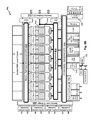
- FIG. 2 illustrates a more detailed architectural diagram of a parser 201 that utilizes micro-cores.
- a parser 201 may implement sixteen separate micro-cores 204 a - n .
- Packets 212 are received into a buffer 252 , where the buffer 252 includes a bank of FIFOs that forms an input queue of packets waiting to be processed by the parser 201 .
- the incoming packets 212 that have been received within the buffer 252 are scheduled/assigned to respective micro-cores 204 a - n .
- Any suitable scheduling algorithm may be employed to assign packets in the queue to the micro-cores 204 a - n .
- a round-robin scheduling algorithm may be employed to assign packets 212 to micro-cores 204 a - n as they become available.
- Each micro-core 204 a is associated with one or more caches 214 a and 214 b .
- the cache 214 a/b is limited to a sufficient size to store the header of an incoming packet 212 . As such, the entirety of a packet 212 is not sent to the micro-core 204 a . Instead, only the first n bytes of the packet 212 (e.g., the bytes forming the header) are directed to the micro-core 204 a .
- the cache 214 a/b is sized at 512 bytes, so that the first 512 bytes of a packet 212 would be loaded into the cache 214 a/b.
- Multiple caches 214 a and 214 b may be associated with a single micro-core 204 a , to allow that micro-core 204 a to operate at or near its full capacity with minimal downtime.
- the second cache 214 b can be filled in with a new packet or emptied of a completed packet.
- that micro-core 204 a can immediately begin processing the packet that had been concurrently loaded into the second cache 214 b .
- the first cache 214 a can then repeat the cycle of emptying the completed packet and loading a new packet.
- Each of the caches 214 a and 214 b can be sized to the maximum threshold memory size to store the packet header.
- each micro-core 204 a is associated with a instruction cache/memory 254 .
- the instruction cache/memory 254 stores the operational programming that the micro-core 204 a performs to process the packet headers.
- the programming in the instruction cache/memory 254 may be used to perform any suitable task by the micro-core 204 a upon a packet.
- the micro-core 204 a can operate to perform classification operations on the packets.
- the micro-core 204 a can operate to drop packets and ensure that the packets are not forwarded to subsequent engines or processing cores.
- the output from the micro-core 204 a is sent to any downstream component 260 that consumes the output from the parser 201 .
- the packet header (when suitably combined with the packet data) can be sent to a DMA 230 for storage and later access.
- the micro-core 204 a can also output information to assist a descriptor generator 232 in generating a descriptor for the packet.
- the micro-core 204 a can be used to forward identification of free FIFOs to the descriptor generator 232 .
- the micro-core 204 a may be used to generate a key that is used by hash logic 234 to generate a hash value.
- the information generated by the micro-core 204 a may also be directed to a packet ordering engine 236 to assist in ordering the packets to be processed by the networking system.
- a packet ordering engine 236 to assist in ordering the packets to be processed by the networking system.
- the micro-core 204 a may provide data used by other packet processing engines and mechanisms 238 within the networking system.
- a dependency list 220 is employed to make sure packets 212 are processed and released by the micro-cores 204 a - n in their proper order. This dependency list is used to make sure that a later packet within a given flow is not released unless an earlier packet has already been processed and released.
- FIG. 3 shows a flowchart of an approach for utilizing a micro-core based parser (e.g., parser 201 , FIG. 2 ) to process packets in a networking system.
- a packet is received in the networking system for processing.
- the packet may be received over one or more physical interface connections and/or data channels.
- the packet may also be stored and/or queued in various interface and receiving buffers (e.g., buffer 252 ) when it has been received for processing.
- the packet is scheduled to a selected micro-core for processing.
- Any suitable scheduling algorithm may be employed to schedule the packets. For example, a simple round robin scheduling algorithm may be employed to assign packets to micro-cores. In addition, more complicated queuing and scheduling algorithms may be employed to ensure fair scheduling of the packets.
- the scheduling activity may also be performed in reliance upon available hardware resources, where scheduling is delayed until sufficient resources are available to handle the processing results from the micro-cores.
- Packets can also be assigned to individual micro-cores that have been programmed to perform specific tasks. For example, one of the micro-cores may be specially programmed to handle a unique protocol, and every packet compliant with that unique protocol would be assigned to that micro-core.
- the packet header is loaded into the cache (e.g., cache 214 a or 214 b ) for its assigned micro-core.
- the cache can be automatically populated with new packet headers as it becomes available.
- One example criteria that may be used to automatically populate the cache is a determination of the number of bytes received, e.g., a number greater than a programmed threshold could be used to control whether the cache is loaded with the packet header. In some embodiments, the maximum value of this threshold is 512 bytes.
- Another example criteria that can be considered is whether there are sufficient hardware resources to process the packet. For example, a determination can be made whether there are sufficient free descriptors that are available for that packet to be able to exit the microcode once the processing is completed.
- the micro-core processes the packet header, e.g., where the micro-core performs one or more ingress functions to process the packet in a networking engine. For example, the micro-core may operate to parse the first n bytes of the packet (e.g., up to the first 512 bytes) to determine the destination of the packet within a host processor or host processor core. If appropriate, the micro-core may also operate to drop the packet, e.g., if the micro-core performances analysis that determines that it is appropriate to drop the packet for lack of a suitable destination. The micro-core may also be operated to modify one or more bits in an ingress descriptor to communicate information derived from the ingress (e.g., an ingress MAC or parsed header) to a downstream component, such as downstream host processor/core.
- the micro-core may operate to parse the first n bytes of the packet (e.g., up to the first 512 bytes) to determine the destination of the packet within a host processor or host processor core. If
- the micro-core may add a pre-pad to the packet.
- a pre-pad For example, consider an example packet format in which a certain portion of the packet is left open, e.g., such that the first 64 bytes of the packet are left open. This open portion of the packet can be occupied by data inserted by the micro-core to communicate parsed information to a downstream component, such as a host processor/core.
- the 64 bytes pre-pad can be filled in 16, 32, 48 or 64 byte portions before the packet data.
- the packets may be released to downstream components (e.g., components 260 ).
- a dependency list (e.g., list 220 ) is used to ensure that the packets are released in an appropriate order.
- FIG. 4A illustrates an example structure 400 that can be used to implement a dependency list in some embodiments.
- Structure 400 is implemented as a set of rows and columns, where each row of the structure 400 corresponds to a bit vector that identifies the dependencies of a specific packet in a micro-core.
- Each bit in a row can be used to identify whether the packet corresponding to that row has a dependency to another packet, e.g., by setting a “1” value in a bit position to indicate a dependency and a “0” value to indicate no dependency. Therefore, a row having all “0” values means that the corresponding packet does not have any dependencies, and can be released upon completion of processing by the micro-core.
- the presence of one or more “1” values for the bit vector in a row means that the corresponding packet has a dependency to at least one other packet, and hence cannot be released until the other packet(s) have been released.
- Each column corresponds to the dependencies that other packets have to a given packet. As a packet is added to a row in the structure 400 , it will include “1” values in the columns for the earlier packets in the same flow. Subsequent packets in the same flow will have rows that are modified to include a “1” value in the column that corresponds to that earlier packet.
- the example structure 400 shown in FIG. 4 is organized for a parser that utilizes sixteen micro-cores (micro-cores 0 - 15 ). Therefore, there are sixteen separate rows that correspond to packets which are received for each of the sixteen micro-cores, where each row identifies the dependencies for its associated packet. Similarly, there are sixteen columns that correspond to each of the sixteen micro-cores, where each column identifies any other packets that have a dependency on the packet associated with that column.
- Each packet may be associated with queue identifiers 401 a - n that identify the packet's positioning in a scheduling queue.
- queue identifiers 401 a - n that identify the packet's positioning in a scheduling queue.
- the specific queue identifier for that packet is associated with the row in the structure 400 .
- dependency list structure 400 Any hardware, software, or combination of hardware and software may be employed to implement dependency list structure 400 .
- the dependency list structure 400 may be implemented using a content addressable memory (CAM).
- CAM content addressable memory
- FIG. 4B shows a flowchart of an approach for populating a dependency list structure 400 according to some embodiments.
- a packet is received for processing. This action is taken, for example, when the cache associated with a micro-core has been populated with the packet header, and is ready to be parsed by the micro-core for processing.
- the row in the dependency list structure that corresponds to the micro-core is associated with the packet. This occurs, for example, by associating the queue identifier for the packet to the specific bit vector for that micro-core's row in the dependency list structure.
- bit vector in the row is then populated at 406 with bit values that appropriately identify the dependencies for the packet associated with the bit vector. For example, the column position for each earlier packet in the same flow is marked with a “1” value to indicate the dependency and the column position for a packet for which there is no dependency is marked with a “0” value.
- FIGS. 5A-D provide an illustration of this process.
- FIG. 5A shows a dependency list structure 500 that has not yet been populated with bit vectors associated with any packets. In other words, there are currently no packets being processed by any micro-cores represented by the dependency list structure 500 .
- micro-core 0 e.g., micro-core 0
- the row 504 in the dependency list structure 500 associated with micro-core 0 is populated with a bit vector for that packet.
- each bit position in the bit vector is marked with a “0” value to indicate that there are no current dependencies for this packet, which makes sense since there are no earlier packets in this flow which are currently being processed by another micro-core.
- the row 506 in the dependency list structure 500 associated with micro-core 7 is populated with a bit vector for that packet. Since the packet associated with row 506 is within the same flow as the packet associated with row 504 but is later in time, a dependency is indicated in the bit vector associated with row 506 .
- Column 507 is associated with the micro-core 0 that is handling the earlier packet (i.e., the micro-core 0 handling the earlier packet represented in row 504 ). Therefore, the bit value in column 507 for row 506 is marked with a “1” value to indicate the dependency. Each other bit position in the bit vector for row 506 is marked with a “0” value to indicate that there are no other current dependencies for this packet.
- the row 508 in the dependency list structure 500 associated with micro-core 12 is populated with a bit vector for that new packet. Since the packet associated with row 508 is later in the same flow as compared to the packets associated with rows 504 and 506 , multiple dependencies need to be indicated in the bit vector associated with row 508 . Like the bit vector for the packet associated with row 506 , the column 507 associated with the micro-core 0 is modified to include a bit value in this column for row 508 (e.g., a “1” value) to indicate the dependency.
- a bit value in this column for row 508 e.g., a “1” value
- Column 509 is associated with the micro-core 7 that is handling the earlier packet (i.e., the micro-core 7 handling the earlier packet represented in row 506 ). Therefore, the bit value in column 509 for row 508 is marked with a “1” value to indicate the dependency. Each other bit position in the bit vector for row 508 is marked with a “0” value to indicate that there are no other current dependencies for this packet.
- the dependency list structure is checked to determine whether that packet is associated with any dependencies that should prevent release of that packet. This is to make sure that a packet later in a flow is not released until any earlier packets in that same flow have already been released.
- FIG. 6 shows a flowchart of an approach for using a dependency list structure to manage release of packets according to some embodiments.
- Release of a packet includes release of the portion of packet data provided to the parser. For example, in some embodiments only the packet header is provided to the parser; release of the packet thus includes release of the header from the parser.
- a packet is identified for which packet parsing has been completed. This action may be taken, for example, when the micro-core associated with a packet has completed its processing, and provides a signal indicating that it is ready to release the packet to one or more downstream components.
- the bit vector associated with the packet is checked to determine whether there are any dependencies for that packet. This action is taken by reviewing the bit values in the bit vector associated with the packet, and checking whether there are any bit values indicative of a dependency, e.g., by checking whether there are any “1” values for any bits in the bit vector.
- the action to be taken at this point depends on whether any dependencies have been identified. From decision box 606 , if there are no identified dependencies, then the packet can be immediately released at 608 . However, if there are any identified dependencies, then the packet cannot be immediately released. Instead, a wait state 610 occurs to wait for the release of the earlier packet(s). After waiting, the procedure loops back to 604 to re-check the status of any dependencies. If all dependencies have been cleared, then the packet can be released at 608 . The loop is repeated if there are still any remaining dependencies.
- FIGS. 7A-F provide an illustration of this process.
- FIG. 7A reproduces the dependency list structure 500 from FIG. 5D , which has already been populated with bit vectors associated with packets.
- the bit vector associated with row 506 includes a bit value in column 507 indicative of a dependency on the packet being handled by micro-core 0 .
- the third packet in the same flow is being handled by micro-core 12 , and hence is represented by the bit vector associated with row 508 .
- the bit vector associated with row 508 includes a bit value in column 507 indicative of a dependency on the packet being handled by micro-core 0 , and also includes a bit value in column 509 indicative of a dependency on the packet being handled by micro-core 7 .
- the packets associated with micro-cores 7 and 12 cannot be released since the bit vectors for each of these packets indicates at least one dependency, e.g., because there is at least one “1” values for a bit in each of these bit vectors.
- the bit vector represented in row 504 for the packet being handled by micro-core 0 does not show any dependencies, e.g., because every bit position shows a value of “0” in the bit vector.
- micro-core 0 has completed the required processing for its packet represented by row 504 , and therefore is to release this packet.
- the bit vector in row 504 for this micro-core 0 is checked to see if there are any dependencies. Since there are no dependencies indicated by the bit vector (e.g., because all bit values are “0”), the packet can be immediately released. As shown in FIG. 7B , the bit vector in row 504 associated with this packet/micro-core is cleared, and the micro-core 0 can now be assigned to process another packet. In addition, any dependencies by other packets upon this packet can also be cleared. This is accomplished by setting the bit values in the column associated with the micro-core to indicate release of the packet. Here, column 507 is associated with micro-core 0 . Therefore, the values that had previously been set in this column to indicate dependencies can now be changed to indicate release of the dependency, e.g., by changing bit value “1” in column 507 for rows 506 and 508 to a bit value of “0”.
- FIG. 7C shows the current state of the dependency list structure 500 after these changes to the bit vectors.
- the packet associated with micro-core 12 represented by row 508 cannot be released since the bit vectors for this packet indicates at least one dependency, e.g., because there is at least one “1” values for a bit in this bit vectors.
- the bit vector represented in row 506 for the packet being handled by micro-core 7 does not show any dependencies, e.g., because every bit position shows a value of “0” in the bit vector.
- micro-core 7 Assume that an instruction is received to release the packet being handled by micro-core 7 .
- the bit vector in row 506 for micro-core 7 is checked to see if there are any dependencies. Since there are no dependencies indicated by the bit vector (e.g., because all bit values are “0”), the packet can be immediately released. As shown in FIG. 7D , the bit vector in row 506 associated with this packet is cleared, and the micro-core 7 can now be assigned to process another packet. In addition, any dependencies by other packets upon this packet can also be cleared. This is accomplished by setting the bit values in the column associated with the micro-core to indicate release of the packet. Here, column 509 is associated with micro-core 7 . Therefore, the values that had previously been set in this column to indicate dependencies can now be changed to indicate release of the dependency, e.g., by changing bit value “1” in column 509 for row 508 to a bit value of “0”.
- FIG. 7E shows the current state of the dependency list structure 500 after these changes to the bit vectors.
- the packet associated with micro-core 12 represented by row 508 can be released since the bit vectors for this packet indicates that there are no dependencies for this packet, e.g., because every bit position shows a value of “0” in the bit vector.
- FIG. 7G now shows the current state of the dependency list structure 500 after this change to the bit vectors.
- FIG. 8 shows a flowchart of an approach for directing packets to specific micro-cores according to some embodiments.
- a packet is received for scheduling.
- the packet may have been received into a receive buffer 252 ( FIG. 2 ) having a set of FIFOs, where the packet is placed into one or more of the FIFOs.
- that packet can be checked to see if it should be assigned to a specific micro-core (e.g., a specific one of micro-cores 204 a - 204 n ).
- a specific micro-core e.g., a specific one of micro-cores 204 a - 204 n .
- certain micro-cores may be specifically programmed to handle certain tasks, protocols, or packet types differently from the other micro-cores.
- the packet can be analyzed to determine whether it pertains to one of the specially programmed micro-cores.
- One approach that can be taken to implement this action is to use an interface mask to spray the incoming packets to different ones/sets of micro-cores based on the specific interface through which the incoming packet was received.
- the mask bits differentiate the packets between the different interfaces, so that certain packets from certain interfaces are directed to corresponding micro-cores.
- the parsing function can be different for the different micro-cores, e.g., because of different contents of the instruction RAMs for different interfaces for the different micro-cores.
- the packet is thereafter scheduled for the identified micro-core.
- the packet header for the packet is loaded into that cache for parsing/processing by the micro-core.
- Embodiments may be utilized in any suitable network processing system or subsystem.
- the micro-core-based parser can be used in a network acceleration engine (NAE) of a network processor.
- NAE network acceleration engine
- FIG. 9A is a diagram illustrating an exemplary system 900 that employs a micro-core-based parser, in accordance with at least one embodiment of the present disclosure.
- this figure shows a network acceleration engine (NAE) 910 , which includes a packet ingress subsystem 930 that performs parsing and classification of incoming packets that are received from the ingress ports 946 of the network interface 904 .
- NAE network acceleration engine
- the packet ingress subsystem 930 performs its parsing and classification functions using a dedicated hardware parser and a number of programmable micro-core processors, e.g., sixteen micro-core processors.
- the NAE 910 provides packets to a packet ordering engine (POE) 920 that is responsible for ensuring that data packet fragments belonging to a specific flow are transmitted by the packet egress subsystem 940 in the same order in which they were received by the packet ingress subsystem 930 .
- POE packet ordering engine
- the packet egress subsystem 940 transmits packets outward through the egress ports 948 in the network interface 904 .
- the packet data path to communicate packets in system 900 includes an I/O distributed interconnect 942 .
- the message data path to communicate messages in system 900 includes a messaging network 933 .
- System 900 employs free descriptor queues that are divided into any number (e.g., twenty) descriptor pools.
- Descriptors are message units of specially formatted words (e.g., 64-bit formatted words).
- each descriptor points to a pre-allocated data buffer in memory where packet data will be stored. Free-in messages are used to initialize the descriptors in the pools.
- the micro-core processors in the NAE Packet Ingress Subsystem 930 are used to determine which descriptor pool to draw descriptors from for each data packet, which thereby determines where each data packet will be written in memory.
- FIG. 9B depicts an example processing system 100 E that may utilize the network acceleration engine 900 of FIG. 9A .
- the processing system 100 E has three bidirectional communication rings (each depicted as a bold-line oval), a plurality of CPUs (e.g. Core-0, Core-1, etc), a plurality of accelerators (e.g. Network Acceleration Engine, POE, Interlaken-LAI) to perform a set of operations, and a plurality of IO blocks (e.g. ICI, general purpose I/O 1E06, etc).
- the three rings can be used for referring to and/or moving packets within the context of an on-chip network.
- each instance of the plurality of CPUs comprises its respective level two cache (e.g. the respective L2 cache, as shown), and comprises its respective level one cache for instructions (e.g. the respective L1-I cache) and its respective level one cache for data (e.g. the respective L1-D cache).
- Each of the CPUs has a virtual CPU (e.g. 1E04 0 , . . . 1E04 3 ) depicted as an oval within a core. These CPUs are separate from the micro-cores in the parser in the Network Acceleration Engine.
- the Memory Distributed Interconnect 1E32 comprises a memory interconnect ring
- the messaging network 1E02 comprises a messaging ring
- the I/O distributed interconnect 1E42 comprises an IO interconnect ring.
- a packet ordering engine to distribute packets in a particular order to a networking output.
- the POE connects to the network acceleration engine (shown as, Network Accel Engine).
- the processing system 100 E includes an L3 cache to connect to the MDI ring 1E32.
- the interconnect serves to connect memory elements to other memory elements, possibly using a message station or direct memory access logic.
- an instance of a CPU e.g. Core-0
- the local cache can be connected to the Memory Distributed Interconnect 1E32 ring.
- a memory interconnect ring 1E32 can be configured to any width, including any width of any interconnected memory, or even multiples of widths of any interconnected memory, or even fractions of the width of any interconnected memory.
- the processing system 100 E depicts an I/O distributed interconnect 1E42, which I/O distributed interconnect 1E42 serves to connect IO blocks (e.g. PCI-E, POE, etc) and accelerators (e.g. network acceleration engine, security engines) to each other, and to the messaging network 1E02 (as shown).
- IO blocks e.g. PCI-E, POE, etc
- accelerators e.g. network acceleration engine, security engines
- the accelerators can be located and configured to perform any specific operation.
- one or more accelerators can be configured to perform such a specific operation autonomously (e.g. without intra-operation intervention by a CPU) and, in some cases, one or more accelerators can be configured to perform operations under programmatic control, which programmatic control can be implemented in any combination of configuration registers and sequencing units (e.g. a finite state machine, a micro-sequencer, etc).
- the Interlaken LA/PCI-E ( 104 ) may be a single module or two separate modules. The Interlaken LA of 104 may be individually enabled or disabled while the PCI-E is always enabled in some embodiments.
- the Interlaken LA/PCI-E ( 104 ) interacts with a number of devices that are outside the boundary of the processing system 100 E, and the number of devices may include, for example, a knowledge-based processor or any look-aside devices 102 (identified as a content-addressable memory or CAM), a host, and peripherals and I/O.
- FIG. 10 depicts a block diagram of an ingress path subsystem for a NAE according to some embodiments.
- the main function of the ingress path subsystem in this example is to receive packets from the network interface and store those packets, via the DMA 1036 , into pre-allocated buffers in a memory subsystem.
- the packet data is received through one or more interfaces 1008 (e.g., through the four Quads 1002 ).
- Quads 1002 may be implemented as Serdes lines, where the Quads 1002 take care of the networking interface protocols for receiving the incoming packets over the network interface 1008 .
- the incoming packets are placed into interface FIFOs 1010 , e.g., twenty interface FIFOs having a total of 16 KBytes.
- the slot generator 1006 generates slots based on interface bandwidth requirements.
- the slot generator 1006 can be programmed to divide up the bandwidth usage as appropriate.
- a credit mechanism can be utilized to prevent overflows at the interface FIFOs 1010 .
- the SGMII interface 1004 is provided to receive control/management input to the system.
- the packet data is read from the interface FIFOs 1010 into a receive buffer (RX buffer 1020 ).
- the Rx Buffer is carved into 524 “contexts”, where a context refers to a separation of the incoming packet streams, e.g., based at least in part on physical input ports and/or stateless packet parsing, such as VLAN-priority for Ethernet interface or the channel number for an Interlaken interface.
- the packets from the interface FIFOs 1010 can be mapped into the different FIFOs within the RX buffer 1020 . For example, a given packet in an interface FIFO may be mapped to a base 0/1 set of RX FIFOs 1011 in the RX buffer 1020 .
- An arbiter 1022 acts as a scheduler to read packet data from the RX buffer 1020 and to feed the packet data for parsing to parser 1028 .
- Any suitable scheduling algorithm may be employed at the arbiter 1022 . For example, a round-robin approach can be taken to read out of the Rx Buffer 1020 . Interface masking may also be applied to direct packets from specific interfaces to specific micro-cores in the parser 1028 .
- scheduling by the arbiter 1022 may also be dependent upon available of hardware resources and free descriptors. Before being considered eligible for scheduling, the total Rx bytes in a context should be greater than a programmable threshold or an end-of-packet (EOP) indication for that section should be present in the Rx buffer.
- EOP end-of-packet
- the parser sequencer 1016 receives control information for the packets.
- the parser sequencer may receive information about the packets such as the length or start address of the packets. This information is used by the arbiter 1022 to schedule reads of packet data from the RX buffer 1020 into the parsers.
- a hardware parser 1024 may be employed to perform parsing on the packet data, in conjunction with the activities of the micro-core parser 1028 .
- the hardware parser 1024 may be used to generate a classification key for each incoming packet.
- the classification key for the incoming packet is sent to one of the programmable micro-cores in the micro-core parser 1028 for any extra classification processing that may be needed.
- the micro-cores within the micro-core parser 1028 are fully programmable processors, as described in more detail below. The programmability of these micro-core processors allows for great flexibility and expansion of the capabilities of the system to perform packet parsing.
- the Rx descriptor generator 1032 detects when a packet crosses a page boundary. When a start of packet (SOP) indication is received, or when a packet crosses a page boundary, the Rx descriptor generator 1032 generates a new free descriptor from the free descriptor queue 1014 and sends the pointer to DMA 1036 . Packet descriptors for the same packet can be from the same Free Descriptor Queue 1014 .
- the DMA block 1036 will pre-pad information to the packet buffer and store the packet data via an I/O distributed Interconnect.
- the Rx descriptor generator 1032 also adds the new descriptor to a descriptor list.
- the RX descriptor generator 1032 may also create a descriptor that points to the list of descriptors where the packet was stored and sends this descriptor along with the Flow ID, Class ID, and other control information 1038 to the Packet Ordering Engine (POE) 1040 .
- POE Packet Ordering Engine
- the free descriptor queue 1014 accepts messages over the messaging network 1012 for returning the freed packet descriptors. Descriptors pointing to the packet data are sent to the Packet Ordering Engine (POE) 1040 .
- the POE 1040 appends its own information to the front of the messages and forwards them to a host processor/processor core.
- the packet data may be processed by certain specialized processing engines 1034 .
- checksumming or CRC processing may occur at engines 1034 . These activities may be controlled based on instructions from the micro-cores in the micro-core parser 1028 .
- CRC key hashing may be performed at block 1030 , which provide a flow identifier to the RX descriptor generator 1032 .
- FIG. 11 shows a diagram of a micro-core architecture 1100 according to some embodiments.
- the micro-core architecture 1100 provides a framework that not only has a small silicon footprint, but also contains enough processing and expansion capability to support packet processing tasks.
- the micro-core architecture 1100 is compliant with standard and/or well known specifications and instruction sets.
- the micro-core architecture 1100 can be implemented to support the MIPS32 Release2 user space instruction set.
- the micro-core architecture 1100 in some embodiments is a five pipe stage, single issue 32-bit processor unit 506 , which supports CISC-style enhanced instructions that perform simple ALU functions directly on data stored in memory as well as register files, and can write processing result either to the register file or memory.
- the memory and registers include a general purpose register (GPR) 1104 , as well as a RAM 1108 that may be incorporated either as part of the micro-core or external to the micro-core.
- the registers within the micro-core may be used to communicate information to the micro-core about the current incoming packet.
- the registers may also be used by the micro-core to communicate specific tasks for downstream hardware to conduct on the current packet.
- a memory mapped control register 1106 provides management and control functionality over the micro-core architecture 1100 . In some embodiments, the control register 1106 and RAM 1108 are not located within the micro-core itself.
- the data is copied into the GPR 1104 for processing by the execution unit 1106 .
- the data is divided into multiple segments, e.g., where a register of 128 bits is divided into four segments of 32 bits each.
- This implementation for the micro-core provides for very efficient processing, since the packet data can therefore be operated upon on a segment basis. If some portion of the data is needed, the micro-core only needs to read in the necessary segment(s), modify or operate upon just that portion of the data, and then write it back to memory.
- the micro-core operates over multiple stages, including (a) instruction fetch (IF); (b) instruction decode (ID); (c) register memory read (REG/MEM1); (d) execute/address generation (EXEC/AGN); and (e) memory writeback (WRB/MEM1).
- FIG. 12 shows functional components of a micro-core 1202 when implemented within an ingress path subsystem, according to some embodiments.
- An instruction cache 1204 e.g., a 4 KB cache
- One or more packet caches 1206 are employed to hold packet header data to be processed by the micro-core 1202 .
- two separate packet caches 1206 e.g., 512 KB data caches
- a content addressable memory (CAM) 1208 e.g., a 3 KB CAM
- CAM content addressable memory
- the CAM 1208 may be used to implement a dependency list structure according to some embodiments; alternatively, the dependency list is implemented in a separate CAM (not shown).
- the micro-core 1202 may also be associated with a shared memory 1210 (e.g., 32 KB shared SRAM) and DCache 1212 (e.g., 512 KB DCache).
- the Shared RAM ( 1210 ) and the Shared CAM can be used to store state data, such as a forwarding table.
- the D-Cache ( 1212 ) is used to store local-variables, if they do not fit inside the GPR.
- One or more output buffers 1214 may be used to hold the outputs from the micro-core 1202 . These outputs include, for example, IP and TCP/IP flags that are sent to a CRC or checksum block. The output may also include a key that is sent to a hash logic unit.
- the micro-core 1202 may output information (e.g., a prepad, discard, or EOP) that is used by a RX descriptor generator to generate descriptors.
- the output can also be the destination for the message.
- the destination can be either a CPU (main host CPU) or can be a Transmit queue inside NAE. In case it is a transmit queue, then the packet will be sent out without host CPU intervention.
- the parser includes one or more micro-cores to process packets in a networking system.
- the micro-cores of the parser read the packet headers, and perform any suitably programmed tasks upon those packets and packet headers.
Abstract
Description
Claims (12)
Priority Applications (1)
| Application Number | Priority Date | Filing Date | Title |
|---|---|---|---|
| US13/164,533 US9244798B1 (en) | 2011-06-20 | 2011-06-20 | Programmable micro-core processors for packet parsing with packet ordering |
Applications Claiming Priority (1)
| Application Number | Priority Date | Filing Date | Title |
|---|---|---|---|
| US13/164,533 US9244798B1 (en) | 2011-06-20 | 2011-06-20 | Programmable micro-core processors for packet parsing with packet ordering |
Publications (1)
| Publication Number | Publication Date |
|---|---|
| US9244798B1 true US9244798B1 (en) | 2016-01-26 |
Family
ID=55086137
Family Applications (1)
| Application Number | Title | Priority Date | Filing Date |
|---|---|---|---|
| US13/164,533 Active US9244798B1 (en) | 2011-06-20 | 2011-06-20 | Programmable micro-core processors for packet parsing with packet ordering |
Country Status (1)
| Country | Link |
|---|---|
| US (1) | US9244798B1 (en) |
Cited By (4)
| Publication number | Priority date | Publication date | Assignee | Title |
|---|---|---|---|---|
| US9455598B1 (en) | 2011-06-20 | 2016-09-27 | Broadcom Corporation | Programmable micro-core processors for packet parsing |
| US20220224564A1 (en) * | 2017-07-10 | 2022-07-14 | Fungible, Inc. | Data processing unit for compute nodes and storage nodes |
| US11777839B2 (en) | 2017-03-29 | 2023-10-03 | Microsoft Technology Licensing, Llc | Data center network with packet spraying |
| US11842216B2 (en) | 2017-07-10 | 2023-12-12 | Microsoft Technology Licensing, Llc | Data processing unit for stream processing |
Citations (25)
| Publication number | Priority date | Publication date | Assignee | Title |
|---|---|---|---|---|
| US4730259A (en) * | 1985-03-01 | 1988-03-08 | Gallant Stephen I | Matrix controlled expert system producible from examples |
| US5170463A (en) * | 1988-12-29 | 1992-12-08 | Sharp Kabushiki Kaisha | Neuro-computer |
| US5995971A (en) * | 1997-09-18 | 1999-11-30 | Micdrosoft Corporation | Apparatus and accompanying methods, using a trie-indexed hierarchy forest, for storing wildcard-based patterns and, given an input key, retrieving, from the forest, a stored pattern that is identical to or more general than the key |
| US6513108B1 (en) * | 1998-06-29 | 2003-01-28 | Cisco Technology, Inc. | Programmable processing engine for efficiently processing transient data |
| US20030182518A1 (en) * | 2002-03-22 | 2003-09-25 | Fujitsu Limited | Parallel processing method for inverse matrix for shared memory type scalar parallel computer |
| US20040103182A1 (en) | 2002-11-27 | 2004-05-27 | Markus Krabel | Distribution in master data management |
| US6791983B1 (en) * | 2000-06-14 | 2004-09-14 | Mindspeed Technologies, Inc. | Content-addressable memory for use with a communication packet processor to retrieve context information |
| US6792575B1 (en) * | 1999-10-21 | 2004-09-14 | Equilibrium Technologies | Automated processing and delivery of media to web servers |
| US20060112190A1 (en) * | 2003-05-29 | 2006-05-25 | Microsoft Corporation | Dependency network based model (or pattern) |
| US20060179267A1 (en) * | 2005-02-08 | 2006-08-10 | International Business Machines Corporation | Method and structure for skewed block-cyclic distribution of lower-dimensional data arrays in higher-dimensional processor grids |
| US20060221850A1 (en) | 2005-03-31 | 2006-10-05 | Teresa Buckley | Field content based packet classification |
| US20060230375A1 (en) * | 2005-04-06 | 2006-10-12 | Lsi Logic Corporation | Integrated circuit with relocatable processor hardmac |
| US7174540B2 (en) * | 2003-06-16 | 2007-02-06 | Microsoft Corporation | Component dependency matrices |
| US7249208B2 (en) * | 2004-05-27 | 2007-07-24 | International Business Machines Corporation | System and method for extending the cross-memory descriptor to describe another partition's memory |
| US20080250232A1 (en) * | 2004-03-29 | 2008-10-09 | Yasuhiko Nakashima | Data Processing Device, Data Processing Program, and Recording Medium Recording Data Processing Program |
| US7475200B1 (en) * | 2001-10-23 | 2009-01-06 | Teplin Application Limited Liability Company | Packet processor memory interface with write dependency list |
| US20090073981A1 (en) | 2007-09-18 | 2009-03-19 | Sensory Networks, Inc. | Methods and Apparatus for Network Packet Filtering |
| US7546371B1 (en) * | 2006-12-29 | 2009-06-09 | Juniper Networks, Inc. | Resource scheduler within a network device |
| US20090285228A1 (en) | 2008-05-19 | 2009-11-19 | Rohati Systems, Inc. | Multi-stage multi-core processing of network packets |
| US20100036997A1 (en) * | 2007-08-20 | 2010-02-11 | Convey Computer | Multiple data channel memory module architecture |
| US20110164140A1 (en) | 2005-08-24 | 2011-07-07 | Exfo Service Assurance Inc. | System and method for monitoring video packets for quantifying video quality |
| US7990867B1 (en) * | 2007-05-03 | 2011-08-02 | Xilinx, Inc. | Pipeline for processing network packets |
| US20120033673A1 (en) | 2010-08-06 | 2012-02-09 | Deepak Goel | Systems and methods for a para-vitualized driver in a multi-core virtual packet engine device |
| US20120236756A1 (en) | 2009-11-30 | 2012-09-20 | Bae Systems Plc | Processing network traffic |
| US20130286860A1 (en) | 2012-04-25 | 2013-10-31 | Anritsu Company | Impairment simulation for network communication to enable voice quality degradation estimation |
-
2011
- 2011-06-20 US US13/164,533 patent/US9244798B1/en active Active
Patent Citations (28)
| Publication number | Priority date | Publication date | Assignee | Title |
|---|---|---|---|---|
| US4730259A (en) * | 1985-03-01 | 1988-03-08 | Gallant Stephen I | Matrix controlled expert system producible from examples |
| US5170463A (en) * | 1988-12-29 | 1992-12-08 | Sharp Kabushiki Kaisha | Neuro-computer |
| US5995971A (en) * | 1997-09-18 | 1999-11-30 | Micdrosoft Corporation | Apparatus and accompanying methods, using a trie-indexed hierarchy forest, for storing wildcard-based patterns and, given an input key, retrieving, from the forest, a stored pattern that is identical to or more general than the key |
| US6513108B1 (en) * | 1998-06-29 | 2003-01-28 | Cisco Technology, Inc. | Programmable processing engine for efficiently processing transient data |
| US6792575B1 (en) * | 1999-10-21 | 2004-09-14 | Equilibrium Technologies | Automated processing and delivery of media to web servers |
| US6791983B1 (en) * | 2000-06-14 | 2004-09-14 | Mindspeed Technologies, Inc. | Content-addressable memory for use with a communication packet processor to retrieve context information |
| US7739452B2 (en) * | 2001-10-23 | 2010-06-15 | Stephen Waller Melvin | Method and apparatus for hardware enforced virtual sequentiality |
| US7475200B1 (en) * | 2001-10-23 | 2009-01-06 | Teplin Application Limited Liability Company | Packet processor memory interface with write dependency list |
| US7506104B1 (en) * | 2001-10-23 | 2009-03-17 | Teplin Application Limited Liability Company | Packet processor memory interface with speculative memory reads |
| US20030182518A1 (en) * | 2002-03-22 | 2003-09-25 | Fujitsu Limited | Parallel processing method for inverse matrix for shared memory type scalar parallel computer |
| US20040103182A1 (en) | 2002-11-27 | 2004-05-27 | Markus Krabel | Distribution in master data management |
| US20060112190A1 (en) * | 2003-05-29 | 2006-05-25 | Microsoft Corporation | Dependency network based model (or pattern) |
| US7174540B2 (en) * | 2003-06-16 | 2007-02-06 | Microsoft Corporation | Component dependency matrices |
| US20080250232A1 (en) * | 2004-03-29 | 2008-10-09 | Yasuhiko Nakashima | Data Processing Device, Data Processing Program, and Recording Medium Recording Data Processing Program |
| US7249208B2 (en) * | 2004-05-27 | 2007-07-24 | International Business Machines Corporation | System and method for extending the cross-memory descriptor to describe another partition's memory |
| US20060179267A1 (en) * | 2005-02-08 | 2006-08-10 | International Business Machines Corporation | Method and structure for skewed block-cyclic distribution of lower-dimensional data arrays in higher-dimensional processor grids |
| US20060221850A1 (en) | 2005-03-31 | 2006-10-05 | Teresa Buckley | Field content based packet classification |
| US20060230375A1 (en) * | 2005-04-06 | 2006-10-12 | Lsi Logic Corporation | Integrated circuit with relocatable processor hardmac |
| US20110164140A1 (en) | 2005-08-24 | 2011-07-07 | Exfo Service Assurance Inc. | System and method for monitoring video packets for quantifying video quality |
| US7930408B1 (en) * | 2006-12-29 | 2011-04-19 | Juniper Networks, Inc. | Resource scheduler within a network device |
| US7546371B1 (en) * | 2006-12-29 | 2009-06-09 | Juniper Networks, Inc. | Resource scheduler within a network device |
| US7990867B1 (en) * | 2007-05-03 | 2011-08-02 | Xilinx, Inc. | Pipeline for processing network packets |
| US20100036997A1 (en) * | 2007-08-20 | 2010-02-11 | Convey Computer | Multiple data channel memory module architecture |
| US20090073981A1 (en) | 2007-09-18 | 2009-03-19 | Sensory Networks, Inc. | Methods and Apparatus for Network Packet Filtering |
| US20090285228A1 (en) | 2008-05-19 | 2009-11-19 | Rohati Systems, Inc. | Multi-stage multi-core processing of network packets |
| US20120236756A1 (en) | 2009-11-30 | 2012-09-20 | Bae Systems Plc | Processing network traffic |
| US20120033673A1 (en) | 2010-08-06 | 2012-02-09 | Deepak Goel | Systems and methods for a para-vitualized driver in a multi-core virtual packet engine device |
| US20130286860A1 (en) | 2012-04-25 | 2013-10-31 | Anritsu Company | Impairment simulation for network communication to enable voice quality degradation estimation |
Non-Patent Citations (5)
| Title |
|---|
| Kuila, K. et al., U.S. Appl. No. 13/164,521, filed Jun. 20, 2011, entitled "Programmable Micro-Core Processors for Packet Parsing". |
| Office Action, dated Mar. 10, 2014, for U.S. Appl. No. 13/164,521, filed Jun. 20, 2011, 10 pages. |
| Office Action, dated May 13, 2013, for U.S. Appl. No. 13/164,521, filed Jun. 20, 2011, 6 pages. |
| Office Action, dated Sep. 25, 2013, for U.S. Appl. No. 13/164,521, filed Jun. 20, 2011, 9 pages. |
| U.S. Appl. No. 13/107,809, filed May 13, 2011, entitled "Implementing Integrated Networking Functions at Wire Speed". |
Cited By (5)
| Publication number | Priority date | Publication date | Assignee | Title |
|---|---|---|---|---|
| US9455598B1 (en) | 2011-06-20 | 2016-09-27 | Broadcom Corporation | Programmable micro-core processors for packet parsing |
| US11777839B2 (en) | 2017-03-29 | 2023-10-03 | Microsoft Technology Licensing, Llc | Data center network with packet spraying |
| US20220224564A1 (en) * | 2017-07-10 | 2022-07-14 | Fungible, Inc. | Data processing unit for compute nodes and storage nodes |
| US11824683B2 (en) * | 2017-07-10 | 2023-11-21 | Microsoft Technology Licensing, Llc | Data processing unit for compute nodes and storage nodes |
| US11842216B2 (en) | 2017-07-10 | 2023-12-12 | Microsoft Technology Licensing, Llc | Data processing unit for stream processing |
Similar Documents
| Publication | Publication Date | Title |
|---|---|---|
| US10749800B2 (en) | Apparatus and method of generating lookups and making decisions for packet modifying and forwarding in a software-defined network engine | |
| US11263158B2 (en) | Programmable computer IO device interface | |
| US8949838B2 (en) | Multi-threaded processing with hardware accelerators | |
| US7310348B2 (en) | Network processor architecture | |
| US8861344B2 (en) | Network processor architecture | |
| EP1832085B1 (en) | Flow assignment | |
| US9461930B2 (en) | Modifying data streams without reordering in a multi-thread, multi-flow network processor | |
| US20120159132A1 (en) | Accelerating Data Packet Parsing | |
| US20070195777A1 (en) | Pipelined packet switching and queuing architecture | |
| US7675928B2 (en) | Increasing cache hits in network processors using flow-based packet assignment to compute engines | |
| KR20040010789A (en) | A software controlled content addressable memory in a general purpose execution datapath | |
| US20200336425A1 (en) | Network system including match processing unit for table-based actions | |
| US9965434B2 (en) | Data packet processing | |
| US9083641B2 (en) | Method and apparatus for improving packet processing performance using multiple contexts | |
| CN115917520A (en) | System for providing LPM implementation for programmable data planes through distributed algorithms | |
| US9244798B1 (en) | Programmable micro-core processors for packet parsing with packet ordering | |
| US11258707B1 (en) | Systems for building data structures with highly scalable algorithms for a distributed LPM implementation | |
| US20060031628A1 (en) | Buffer management in a network device without SRAM | |
| US20220166718A1 (en) | Systems and methods to prevent packet reordering when establishing a flow entry | |
| US9455598B1 (en) | Programmable micro-core processors for packet parsing | |
| WO2003090018A2 (en) | Network processor architecture | |
| US7940764B2 (en) | Method and system for processing multicast packets | |
| US20060140203A1 (en) | System and method for packet queuing | |
| US20230224261A1 (en) | Network interface device | |
| Garg et al. | Network Processor Architecture for Next Generation Packet Format |
Legal Events
| Date | Code | Title | Description |
|---|---|---|---|
| AS | Assignment |
Owner name: NETLOGIC MICROSYSTEMS, INC., CALIFORNIA Free format text: ASSIGNMENT OF ASSIGNORS INTEREST;ASSIGNORS:KUILA, KAUSHIK;HASS, DAVID T.;REEL/FRAME:026780/0840 Effective date: 20110808 |
|
| AS | Assignment |
Owner name: NETLOGIC I LLC, DELAWARE Free format text: CHANGE OF NAME;ASSIGNOR:NETLOGIC MICROSYSTEMS, INC.;REEL/FRAME:035443/0824 Effective date: 20130123 Owner name: BROADCOM CORPORATION, CALIFORNIA Free format text: ASSIGNMENT OF ASSIGNORS INTEREST;ASSIGNOR:NETLOGIC I LLC;REEL/FRAME:035443/0763 Effective date: 20150327 |
|
| STCF | Information on status: patent grant |
Free format text: PATENTED CASE |
|
| AS | Assignment |
Owner name: BANK OF AMERICA, N.A., AS COLLATERAL AGENT, NORTH CAROLINA Free format text: PATENT SECURITY AGREEMENT;ASSIGNOR:BROADCOM CORPORATION;REEL/FRAME:037806/0001 Effective date: 20160201 Owner name: BANK OF AMERICA, N.A., AS COLLATERAL AGENT, NORTH Free format text: PATENT SECURITY AGREEMENT;ASSIGNOR:BROADCOM CORPORATION;REEL/FRAME:037806/0001 Effective date: 20160201 |
|
| CC | Certificate of correction | ||
| AS | Assignment |
Owner name: AVAGO TECHNOLOGIES GENERAL IP (SINGAPORE) PTE. LTD., SINGAPORE Free format text: ASSIGNMENT OF ASSIGNORS INTEREST;ASSIGNOR:BROADCOM CORPORATION;REEL/FRAME:041706/0001 Effective date: 20170120 Owner name: AVAGO TECHNOLOGIES GENERAL IP (SINGAPORE) PTE. LTD Free format text: ASSIGNMENT OF ASSIGNORS INTEREST;ASSIGNOR:BROADCOM CORPORATION;REEL/FRAME:041706/0001 Effective date: 20170120 |
|
| AS | Assignment |
Owner name: BROADCOM CORPORATION, CALIFORNIA Free format text: TERMINATION AND RELEASE OF SECURITY INTEREST IN PATENTS;ASSIGNOR:BANK OF AMERICA, N.A., AS COLLATERAL AGENT;REEL/FRAME:041712/0001 Effective date: 20170119 |
|
| AS | Assignment |
Owner name: AVAGO TECHNOLOGIES INTERNATIONAL SALES PTE. LIMITE Free format text: MERGER;ASSIGNOR:AVAGO TECHNOLOGIES GENERAL IP (SINGAPORE) PTE. LTD.;REEL/FRAME:047229/0408 Effective date: 20180509 |
|
| AS | Assignment |
Owner name: AVAGO TECHNOLOGIES INTERNATIONAL SALES PTE. LIMITE Free format text: CORRECTIVE ASSIGNMENT TO CORRECT THE EFFECTIVE DATE PREVIOUSLY RECORDED ON REEL 047229 FRAME 0408. ASSIGNOR(S) HEREBY CONFIRMS THE THE EFFECTIVE DATE IS 09/05/2018;ASSIGNOR:AVAGO TECHNOLOGIES GENERAL IP (SINGAPORE) PTE. LTD.;REEL/FRAME:047349/0001 Effective date: 20180905 |
|
| AS | Assignment |
Owner name: AVAGO TECHNOLOGIES INTERNATIONAL SALES PTE. LIMITE Free format text: CORRECTIVE ASSIGNMENT TO CORRECT THE PATENT NUMBER 9,385,856 TO 9,385,756 PREVIOUSLY RECORDED AT REEL: 47349 FRAME: 001. ASSIGNOR(S) HEREBY CONFIRMS THE MERGER;ASSIGNOR:AVAGO TECHNOLOGIES GENERAL IP (SINGAPORE) PTE. LTD.;REEL/FRAME:051144/0648 Effective date: 20180905 |
|
| MAFP | Maintenance fee payment |
Free format text: PAYMENT OF MAINTENANCE FEE, 4TH YEAR, LARGE ENTITY (ORIGINAL EVENT CODE: M1551); ENTITY STATUS OF PATENT OWNER: LARGE ENTITY Year of fee payment: 4 |
|
| MAFP | Maintenance fee payment |
Free format text: PAYMENT OF MAINTENANCE FEE, 8TH YEAR, LARGE ENTITY (ORIGINAL EVENT CODE: M1552); ENTITY STATUS OF PATENT OWNER: LARGE ENTITY Year of fee payment: 8 |