US9244262B2 - Low cost focussing system giving high concentrations - Google Patents
Low cost focussing system giving high concentrations Download PDFInfo
- Publication number
- US9244262B2 US9244262B2 US13/703,575 US201113703575A US9244262B2 US 9244262 B2 US9244262 B2 US 9244262B2 US 201113703575 A US201113703575 A US 201113703575A US 9244262 B2 US9244262 B2 US 9244262B2
- Authority
- US
- United States
- Prior art keywords
- reflective element
- focus
- reflective
- focussing
- focussing system
- Prior art date
- Legal status (The legal status is an assumption and is not a legal conclusion. Google has not performed a legal analysis and makes no representation as to the accuracy of the status listed.)
- Active, expires
Links
Images


Classifications
-
- G—PHYSICS
- G02—OPTICS
- G02B—OPTICAL ELEMENTS, SYSTEMS OR APPARATUS
- G02B19/00—Condensers, e.g. light collectors or similar non-imaging optics
- G02B19/0033—Condensers, e.g. light collectors or similar non-imaging optics characterised by the use
- G02B19/0038—Condensers, e.g. light collectors or similar non-imaging optics characterised by the use for use with ambient light
- G02B19/0042—Condensers, e.g. light collectors or similar non-imaging optics characterised by the use for use with ambient light for use with direct solar radiation
-
- F—MECHANICAL ENGINEERING; LIGHTING; HEATING; WEAPONS; BLASTING
- F03—MACHINES OR ENGINES FOR LIQUIDS; WIND, SPRING, OR WEIGHT MOTORS; PRODUCING MECHANICAL POWER OR A REACTIVE PROPULSIVE THRUST, NOT OTHERWISE PROVIDED FOR
- F03G—SPRING, WEIGHT, INERTIA OR LIKE MOTORS; MECHANICAL-POWER PRODUCING DEVICES OR MECHANISMS, NOT OTHERWISE PROVIDED FOR OR USING ENERGY SOURCES NOT OTHERWISE PROVIDED FOR
- F03G6/00—Devices for producing mechanical power from solar energy
- F03G6/001—Devices for producing mechanical power from solar energy having photovoltaic cells
-
- F—MECHANICAL ENGINEERING; LIGHTING; HEATING; WEAPONS; BLASTING
- F03—MACHINES OR ENGINES FOR LIQUIDS; WIND, SPRING, OR WEIGHT MOTORS; PRODUCING MECHANICAL POWER OR A REACTIVE PROPULSIVE THRUST, NOT OTHERWISE PROVIDED FOR
- F03G—SPRING, WEIGHT, INERTIA OR LIKE MOTORS; MECHANICAL-POWER PRODUCING DEVICES OR MECHANISMS, NOT OTHERWISE PROVIDED FOR OR USING ENERGY SOURCES NOT OTHERWISE PROVIDED FOR
- F03G6/00—Devices for producing mechanical power from solar energy
- F03G6/06—Devices for producing mechanical power from solar energy with solar energy concentrating means
- F03G6/062—Parabolic point or dish concentrators
-
- F—MECHANICAL ENGINEERING; LIGHTING; HEATING; WEAPONS; BLASTING
- F03—MACHINES OR ENGINES FOR LIQUIDS; WIND, SPRING, OR WEIGHT MOTORS; PRODUCING MECHANICAL POWER OR A REACTIVE PROPULSIVE THRUST, NOT OTHERWISE PROVIDED FOR
- F03G—SPRING, WEIGHT, INERTIA OR LIKE MOTORS; MECHANICAL-POWER PRODUCING DEVICES OR MECHANISMS, NOT OTHERWISE PROVIDED FOR OR USING ENERGY SOURCES NOT OTHERWISE PROVIDED FOR
- F03G6/00—Devices for producing mechanical power from solar energy
- F03G6/06—Devices for producing mechanical power from solar energy with solar energy concentrating means
- F03G6/068—Devices for producing mechanical power from solar energy with solar energy concentrating means having other power cycles, e.g. Stirling or transcritical, supercritical cycles; combined with other power sources, e.g. wind, gas or nuclear
-
- F24J2/1047—
-
- F24J2/15—
-
- F24J2/16—
-
- F24J2/38—
-
- F—MECHANICAL ENGINEERING; LIGHTING; HEATING; WEAPONS; BLASTING
- F24—HEATING; RANGES; VENTILATING
- F24S—SOLAR HEAT COLLECTORS; SOLAR HEAT SYSTEMS
- F24S23/00—Arrangements for concentrating solar-rays for solar heat collectors
- F24S23/70—Arrangements for concentrating solar-rays for solar heat collectors with reflectors
- F24S23/75—Arrangements for concentrating solar-rays for solar heat collectors with reflectors with conical reflective surfaces
-
- F—MECHANICAL ENGINEERING; LIGHTING; HEATING; WEAPONS; BLASTING
- F24—HEATING; RANGES; VENTILATING
- F24S—SOLAR HEAT COLLECTORS; SOLAR HEAT SYSTEMS
- F24S23/00—Arrangements for concentrating solar-rays for solar heat collectors
- F24S23/70—Arrangements for concentrating solar-rays for solar heat collectors with reflectors
- F24S23/77—Arrangements for concentrating solar-rays for solar heat collectors with reflectors with flat reflective plates
-
- F—MECHANICAL ENGINEERING; LIGHTING; HEATING; WEAPONS; BLASTING
- F24—HEATING; RANGES; VENTILATING
- F24S—SOLAR HEAT COLLECTORS; SOLAR HEAT SYSTEMS
- F24S23/00—Arrangements for concentrating solar-rays for solar heat collectors
- F24S23/70—Arrangements for concentrating solar-rays for solar heat collectors with reflectors
- F24S23/80—Arrangements for concentrating solar-rays for solar heat collectors with reflectors having discontinuous faces
-
- F—MECHANICAL ENGINEERING; LIGHTING; HEATING; WEAPONS; BLASTING
- F24—HEATING; RANGES; VENTILATING
- F24S—SOLAR HEAT COLLECTORS; SOLAR HEAT SYSTEMS
- F24S50/00—Arrangements for controlling solar heat collectors
- F24S50/20—Arrangements for controlling solar heat collectors for tracking
-
- G—PHYSICS
- G02—OPTICS
- G02B—OPTICAL ELEMENTS, SYSTEMS OR APPARATUS
- G02B1/00—Optical elements characterised by the material of which they are made; Optical coatings for optical elements
- G02B1/10—Optical coatings produced by application to, or surface treatment of, optical elements
- G02B1/12—Optical coatings produced by application to, or surface treatment of, optical elements by surface treatment, e.g. by irradiation
-
- G—PHYSICS
- G02—OPTICS
- G02B—OPTICAL ELEMENTS, SYSTEMS OR APPARATUS
- G02B19/00—Condensers, e.g. light collectors or similar non-imaging optics
- G02B19/0004—Condensers, e.g. light collectors or similar non-imaging optics characterised by the optical means employed
- G02B19/0019—Condensers, e.g. light collectors or similar non-imaging optics characterised by the optical means employed having reflective surfaces only (e.g. louvre systems, systems with multiple planar reflectors)
- G02B19/0023—Condensers, e.g. light collectors or similar non-imaging optics characterised by the optical means employed having reflective surfaces only (e.g. louvre systems, systems with multiple planar reflectors) at least one surface having optical power
-
- G—PHYSICS
- G02—OPTICS
- G02B—OPTICAL ELEMENTS, SYSTEMS OR APPARATUS
- G02B19/00—Condensers, e.g. light collectors or similar non-imaging optics
- G02B19/0033—Condensers, e.g. light collectors or similar non-imaging optics characterised by the use
-
- H01L31/0525—
-
- H01L31/0547—
-
- H—ELECTRICITY
- H10—SEMICONDUCTOR DEVICES; ELECTRIC SOLID-STATE DEVICES NOT OTHERWISE PROVIDED FOR
- H10F—INORGANIC SEMICONDUCTOR DEVICES SENSITIVE TO INFRARED RADIATION, LIGHT, ELECTROMAGNETIC RADIATION OF SHORTER WAVELENGTH OR CORPUSCULAR RADIATION
- H10F77/00—Constructional details of devices covered by this subclass
- H10F77/40—Optical elements or arrangements
- H10F77/42—Optical elements or arrangements directly associated or integrated with photovoltaic cells, e.g. light-reflecting means or light-concentrating means
- H10F77/488—Reflecting light-concentrating means, e.g. parabolic mirrors or concentrators using total internal reflection
-
- Y—GENERAL TAGGING OF NEW TECHNOLOGICAL DEVELOPMENTS; GENERAL TAGGING OF CROSS-SECTIONAL TECHNOLOGIES SPANNING OVER SEVERAL SECTIONS OF THE IPC; TECHNICAL SUBJECTS COVERED BY FORMER USPC CROSS-REFERENCE ART COLLECTIONS [XRACs] AND DIGESTS
- Y02—TECHNOLOGIES OR APPLICATIONS FOR MITIGATION OR ADAPTATION AGAINST CLIMATE CHANGE
- Y02E—REDUCTION OF GREENHOUSE GAS [GHG] EMISSIONS, RELATED TO ENERGY GENERATION, TRANSMISSION OR DISTRIBUTION
- Y02E10/00—Energy generation through renewable energy sources
- Y02E10/40—Solar thermal energy, e.g. solar towers
- Y02E10/46—Conversion of thermal power into mechanical power, e.g. Rankine, Stirling or solar thermal engines
-
- Y—GENERAL TAGGING OF NEW TECHNOLOGICAL DEVELOPMENTS; GENERAL TAGGING OF CROSS-SECTIONAL TECHNOLOGIES SPANNING OVER SEVERAL SECTIONS OF THE IPC; TECHNICAL SUBJECTS COVERED BY FORMER USPC CROSS-REFERENCE ART COLLECTIONS [XRACs] AND DIGESTS
- Y02—TECHNOLOGIES OR APPLICATIONS FOR MITIGATION OR ADAPTATION AGAINST CLIMATE CHANGE
- Y02E—REDUCTION OF GREENHOUSE GAS [GHG] EMISSIONS, RELATED TO ENERGY GENERATION, TRANSMISSION OR DISTRIBUTION
- Y02E10/00—Energy generation through renewable energy sources
- Y02E10/40—Solar thermal energy, e.g. solar towers
- Y02E10/47—Mountings or tracking
-
- Y—GENERAL TAGGING OF NEW TECHNOLOGICAL DEVELOPMENTS; GENERAL TAGGING OF CROSS-SECTIONAL TECHNOLOGIES SPANNING OVER SEVERAL SECTIONS OF THE IPC; TECHNICAL SUBJECTS COVERED BY FORMER USPC CROSS-REFERENCE ART COLLECTIONS [XRACs] AND DIGESTS
- Y02—TECHNOLOGIES OR APPLICATIONS FOR MITIGATION OR ADAPTATION AGAINST CLIMATE CHANGE
- Y02E—REDUCTION OF GREENHOUSE GAS [GHG] EMISSIONS, RELATED TO ENERGY GENERATION, TRANSMISSION OR DISTRIBUTION
- Y02E10/00—Energy generation through renewable energy sources
- Y02E10/50—Photovoltaic [PV] energy
- Y02E10/52—PV systems with concentrators
Definitions
- Solar energy can be utilized in a number of ways but for the production of 5-500 kW electrical power in dry sunny regions, where water is scarce, there are two leading possibilities: concentrated photo-voltaic (CPV) systems; and solar heated Stirling engines driving electrical generators.
- CPV concentrated photo-voltaic
- ZEMAX Optima Research Ltd, 8 Riverside Business Park, Stoney Common Road, Stansted, CM24 8PL, United Kingdom e.g. ZEMAX (ref 4). These tools are particularly useful for more detailed requirements such as attaining uniform temperature of the heater assembly or uniform illumination of the photo-voltaic cell.
- a focussing system for concentrating radiation onto a target surface, comprising: a first reflective element forming part of a conical surface axially aligned along a first alignment axis, the first reflective element being positioned such that when planar radiation is incident on the first reflective element in a direction parallel to the first alignment axis, the planar radiation is focussed towards a first focus lying along the first alignment axis, wherein said part of the conical surface is contained within a sector having an included angle of less than 180 degrees; and a second reflective element having a reflective surface that at all points is flat in a direction parallel to a single reference direction, the second reflective element being positioned between the first reflective element and the first focus such that, when planar radiation is incident on the first reflective element in a direction parallel to the first alignment axis, radiation reflected from the first reflective element onto the second reflective element is focussed towards a second focus.
- the first focus is a line focus (i.e. a focus having an elongate form approximating a portion of a line).
- a line focus is most constrained in directions within a horizontal plane (when the first alignment axis is vertical), this focus may be referred to as a “horizontal focus”.
- the second focus is a point focus (i.e. a focus that is spatially constrained in all directions, thereby approximating a point).
- a focus is spatially constrained in directions within a vertical plane relative to the first focus, this focus may be referred to as a “vertical focus”.
- the second reflective element may be formed from a parabolic mirror with an axis of curvature perpendicular to the first alignment axis—such a mirror has the shape of part of a parabolic trough.
- This arrangement thus uses reflective elements that can be readily formed from flat sheet by simple bending—such surfaces are called developable.
- developable three mutually orthogonal planes can be chosen in which the curvature of the surface is only non-zero in one of the planes: for the surface of a cone, the xy plane, where z is the axis of the cone; for the surface of a parabolic trough, the xy plane, where z is along the base of the trough.
- Two-dimensional geometries of this kind can be referred to as “two-dimensional” and are characterized generally by surface geometries built up from locally flat linear elements (i.e. elements that have no curvature in a direction parallel to their length).
- first reflective elements which comprise a reflective surface corresponding to a part of a cone (a first order aspheric surface)
- the linear elements would run continuously from a lower extremity of the element to an upper extremity of the element, and be aligned towards the tip of the cone.
- the second reflective elements where all parts of the surface are flat along the same reference direction, the linear elements are (infinitesimally thin) parallel strips.
- Such “two-dimensional” geometries provide several advantages relative to the alternative “three-dimensional” geometries (i.e. geometries having local curvature that cannot be achieved by simple bending) that are used in the prior art in the most similar contexts.
- a “two-dimensional” design in contrast, can be manufactured from reflective sheet by the simple process of bending.
- a “three-dimensional” design has to start with a material that can be machined or deformed, and a more complex manufacturing process is required to accurately achieve the required geometry.
- Glass is a material that is frequently used as the basis of a “three-dimensional” concentrator.
- the shape can be achieved by deforming a plate into a mold by a process called slump forming
- the reflective surface is achieved by the coating of the glass with a thin reflective coating—this process is familiar in the silvering of conventional glass mirrors; however, the material is not robust.
- the provision of separate reflective elements provides greater flexibility in comparison to systems that rely on a single reflective element, because of the relative freedom to orient and/or position the reflective elements to achieve different focus positions.
- the first and second reflectors may be configured so that the second focus is above the second reflector, such that radiation approaches the focus from below.
- This arrangement may be useful where the target for the focussed radiation is within a housing provided for restricting upward movement of gas in the region of the target (to reduce convective losses).
- this approach enables radiation windows to open out downwards and/or be positioned in a lower part of the housing, which naturally restricts escape of hot gases relative to arrangements where this is not the case.
- the reflective elements may be arranged so that the second focus is in close proximity to one or both of the first or second reflective elements, which makes it easier to provide a light, low cost support structure.
- the second focus can be arranged relative to the first alignment axis so as to be radially outside of one or both of the first and second reflective elements, or radially inward of one or both of the first and second reflective elements.
- the second focus can be arranged to be longitudinally nearer to the source of the incident radiation than one or both of the first and second reflective elements, or can be longitudinally further from the source than one or both of the first and second reflective elements.
- the reflective elements can be formed by simple bending or rolling of flat strips of material.
- the flat strips are rectangular to facilitate manufacture.
- the strips may also be formed from aluminium, which can be shaped efficiently, and is light and strong.
- the first or second reflective element may be formed from a plurality of reflective elements.
- the reflective elements within each group can be spaced apart to allow air to flow between the individual elements, thereby reducing wind forces and enabling a lighter, lower cost construction, while not altering the collecting area. If the individual elements are simply displaced vertically (parallel to the first alignment axis), relative to where they would have been had they been joined integrally, then the ‘footprint’ or collecting area of each reflective element (i.e. of each element formed from a plurality of strips) is not altered.
- the shapes of the reflective surfaces of the reflective elements can be adapted so as to produce a uniform power distribution at the second focus. This can be achieved by controlling the overall shape of the reflective elements or by applying a suitably shaped non-reflective mask to the reflective elements.
- the reflective elements may be formed into the required shape by either using curved guides or by clamping nominally flat strips/facets of material in such a way as to impose the boundary conditions that force them to bend as desired.
- the reflective elements may thus be formed at the location where the solar focussing system is to be deployed, thus avoiding careful (and therefore expensive) transportation of pre-shaped components.
- the reflective elements may also be tuned on site, by adjusting the clamping conditions, for an optimal focus, or tuned to correct for damage of the flat starting materials during transportation or for general wear and tear and/or fatigue.
- a multiple target focussing system may be provided, which consists of two or more focussing systems, each configured to produce different second foci.
- the different second foci may be spatially separated from each other, for example along a direction parallel to the first alignment axis of one or more of the focussing systems in the multiple target focussing system and/or along a direction perpendicular to the first alignment axis of one or more of the focussing systems in the multiple target focussing system. In this way, it is possible simultaneously to concentrate radiation onto more than one target in a flexible manner.
- a solar powered system comprising: a heat driven engine; a heat exchanger surface for receiving solar energy to drive the heat driven engine; and a focussing system according to an embodiment of the invention that is configured to concentrate solar radiation onto the heat exchanger surface.
- the heat exchanger surface may be in the form of heater tubes within a cavity defined by a housing, for example.
- the reflective elements are arranged so that light will be incident on the heat exchanger from below, which makes it easier to control convective heat losses.
- the solar focussing system is preferably configured to direct radiation in an upwards direction towards the secondary focus.
- a concentrator and/or homogenizer may be provided to further control the degree of focus and/or distribution of radiation incident on the heat exchanger.
- the solar powered system may further comprise a second heat exchanger surface, spaced apart from the first heat exchanger surface, for receiving solar energy to drive a different part of the heat driven engine to the first heat exchanger surface.
- a multiple target focussing system according to an embodiment of the invention may be provided for independently focussing solar radiation onto each of the heat exchanger surfaces.
- the heat driven engine is a linear multi-cylinder Stirling engine comprising a plurality of longitudinally spaced apart heat exchangers (e.g. one for each cylinder), for example.
- Using sets of separate reflective elements rather than a single reflector provides the necessary flexibility for efficiently dealing with this situation, even where the axis of the linear engine is parallel to the incident solar light.
- Such an arrangement can also be useful where it is desired to focus light onto different heat exchangers that are separated from each other in a direction perpendicular to the first alignment axes of the reflective elements (and to the incident solar light).
- this approach might be useful where a linear multi-cylinder Stirling engine is to be oriented horizontally.
- This approach might also be useful where different sets of reflective elements are to be used to focus light onto different elements of a single heat exchanger (e.g. heater tubes) where these elements are displaced significantly from the axis of the heat exchanger.
- a solar powered system comprising: a photo-voltaic generator; and a focussing system according to an embodiment of the invention which is configured to concentrate solar radiation onto the photo-voltaic generator.
- the system may have a housing to contain the photo-voltaic generator, with means for dissipating rejected heat and for protecting the photo-voltaic generator from damage.
- the receiving face of the photo-voltaic generator is directed downwards so that unwanted debris is discouraged from accumulating on the receiving surface.
- the focussing system can be adapted to focus light upwards onto such a surface by suitable positioning and orientation of the reflectors.
- a secondary element may be provided to help ensure that the solar flux is optimally focussed onto the surface of the photocell. This element could be a concentrator or a homogenizer.
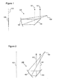
- FIG. 1 is a schematic side view of a focussing system comprising a first reflective element formed from a sector of the surface of a cone and a second reflective element formed from a mirror having curvature along a single direction, and shows the position of a line focus running along the first alignment axis;
- FIG. 2 is a schematic side view of a focussing system of the general type shown in FIG. 1 , wherein the first and second reflective elements are configured so as to form a point focus that is well above both of the reflective elements, so rays converge almost vertically towards the point focus, and further from the first alignment axis that the first and second reflective elements;
- FIG. 3 is a schematic side view of a focussing system similar to that shown in FIG. 2 , except that the point focus is formed nearer to the first alignment axis than the first and second reflective elements;
- FIG. 4 is a schematic side view of a focussing system of the general type shown in FIG. 1 , wherein the first and second reflective elements are configured to form a point focus that is only just higher than the first reflective element and further from the first alignment axis than the first reflective element;
- FIG. 5 a is a schematic side view of a focussing system in which the point focus is formed at a position in between the first and second reflective elements;
- FIG. 5 b is a schematic perspective view of the focussing system according to FIG. 5 a;
- FIG. 6 is a schematic side view of a focussing system in which the first and second reflective elements are configured to produce a point focus that is directly below the second reflective element;
- FIG. 7 is a schematic side view of a focussing system comprising a third reflective element configured to re-direct the point focus directly upwards;
- FIG. 8 is a schematic side view of a focussing system comprising a secondary concentrator to further concentrate light focussed from the second reflective element;
- FIG. 9 is a schematic top view of a focussing system comprises a plurality of pairs of first and second reflective elements
- FIG. 10 is a schematic side view of an arrangement comprising two first reflective elements, separated from each other by an air gap and configured so that horizontal foci and vertical foci originating from different reflective elements converge respectively onto the exit and entrance of a secondary concentrator;
- FIG. 11 a is a magnified view of the secondary concentrator and incident rays shown in FIG. 10 ;
- FIG. 11 b is a schematic perspective view of the secondary concentrator of FIG. 11 a showing the horizontal and vertical foci;
- FIG. 12 is a schematic side view of a variation similar to that depicted in FIGS. 10 , 11 a and 11 b except that two separated second reflective elements are provided instead of two separated first reflective elements;
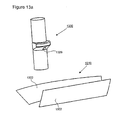
- FIG. 13 a is a schematic perspective view illustrating use of a focussing system of the type shown in FIG. 2 configured to focus light onto a heating element of a Stirling engine;
- FIG. 13 b is a schematic side view illustrating use of three focussing systems of the type shown in FIG. 2 each configured to focus light onto a different heating element of a Stirling engine;
- FIG. 14 is a schematic side view illustrating use of a focussing system according to the type shown in FIG. 4 with a Photo-Voltaic generator;
- FIGS. 15 a to 15 c illustrate a specific example of an aberration-free focussing system
- FIG. 16 is a schematic side view of a multiple target focussing system deployed to focus radiation onto three different cylinders of a multi-cylinder Stirling engine longitudinally aligned with the direction of incidence of solar radiation;
- FIG. 17 is a schematic side view of a multiple target focussing system deployed to focus radiation onto three different cylinders of a multi-cylinder Stirling engine longitudinally aligned perpendicular to the direction of incidence of solar radiation.
- FIG. 1 is a schematic illustration of a focussing system 110 according to an embodiment of the invention.
- the focussing system 110 comprises a first reflective element 100 and a second reflective element 102 .
- the first reflective element 100 takes the form of a portion of the surface of a cone (a conical surface) having a first alignment axis 103 .
- the first reflective element 100 reflects light towards a line focus 105 along the first alignment axis when planar light 101 is incident on the focussing system 110 in a direction parallel to the first alignment axis 103 .
- the line focus 105 can best be depicted by viewing in a horizontal plane (perpendicular to the axis 103 of the cone), and can therefore be referred to as a “horizontal focus”.
- the second reflective element 102 comprises a curved reflecting surface that is positioned between the first reflective element 100 and its line focus 105 .
- the second reflective element 102 has curvature in only one direction and the axis of curvature at a point is perpendicular to the cone axis.
- the second reflective element 102 reflects the light from the first reflective element and produces a new focus 104 that will generally have a higher concentration than the horizontal focus 105 .
- This new focus 104 is referred to below as the “second focus”, but as the focussing action can best be seen in the vertical plane (i.e. viewed in a vertical plane, the spatial extent of the second focus is smaller than the spatial extent of the horizontal focus), the second focus may be considered to be a vertical focus.
- the second focus 104 is in a plane that contains the first alignment axis 103 and is normal to the second reflective element 102 .
- the second focus 104 is placed behind or in the vicinity of the first reflective element 100 then provision may need to be made for the passage of the focused light through the first reflective element 100 and for the installation of suitable receiver components. This can be done by having a suitable opening in the first reflective element 100 or by splitting the first reflective element 100 in two with a gap for the reflected focus.
- FIGS. 2 to 6 show preferred embodiments that produce point foci 104 .
- the first reflective element 100 comprises a sector of the surface of a cone in combination with a second reflective element 102 consisting of a “two-dimensional” parabolic reflector (i.e. a reflector which has curvature along a single direction in the form of a parabola).
- a “two-dimensional” parabolic reflector i.e. a reflector which has curvature along a single direction in the form of a parabola.
- the surface of the cone is inclined at 45 degrees, it is possible to achieve an aberration free focus, as described in detail below with reference to FIGS. 15 a to 15 c . If the surface of the cone is inclined at an angle other than 45 degrees to the first alignment axis, the point focus is approximate.
- the focussing system 110 is arranged so that light is directed upwards towards a second focus 104 positioned above and just behind (radially outward from) the first reflective element 100 .
- the arrangement has two features that make it particularly attractive for Solar Stirling applications. Firstly the upward direction of the light into the second focus 104 makes it suitable for entry into a cavity type receiver where convection losses need to be minimized (the opening for the light will be in a lower portion of the cavity, whereas hot gases will tend to rise within the cavity). Secondly, having the second focus 104 close to the first reflective element 100 allows the Engine/Receiver to be positioned close to the first reflective element 100 . Positioning the major component masses in close proximity to each other increases the scope for designing a light, low cost support structure.
- the second reflective element 102 is adjusted to put the second focus 104 above and just beyond the second reflective element 102 (i.e. the second focus 104 is nearer to the first alignment axis 103 than the second reflective element 102 and above the second reflective element 102 ). Again the upward direction of light rays to a second focus 104 makes this arrangement particularly suitable for Solar Stirling applications.
- the second reflective element 102 is adjusted to put the second focus 104 further behind the first reflective element 100 (i.e. further from the first alignment axis 103 ) and at a lower height, relative to the arrangement of FIG. 2 .
- the light rays converging on the second focus 104 in this arrangement will be much closer to the horizontal than in the arrangement of FIG. 2 , so are less suited to Solar Stirling applications from the point of view of minimizing convection losses. However, it is more compact and would be very suited to photo-voltaic applications where convection losses are not an issue.
- FIGS. 5 a (side view) and 5 b (perspective view) show a compact arrangement in which the second focus 104 is positioned between the first reflective element 100 and the second reflective element 102 .
- this variation is primarily suited to photo-voltaic applications. Note that the target at the second focus 104 will cause a small shadow on the second reflective element 102 .
- FIG. 6 shows an embodiment in which the second focus 104 is arranged to be below the second reflective element 102 (i.e. further from the source of the incident planar radiation 101 than the second reflective element 102 ), illustrating the flexibility of the overall approach and the ease with which the focussing system 110 can be adapted to fit with different operating environments and requirements.
- FIG. 7 shows an alternative embodiment in which a third reflective element 108 is provided, in this case in the form of a plane mirror.
- the third reflective element 108 is configured so as to cause rays converging towards the second focus 104 to be re-directed towards a new focus 109 .
- the third reflective surface 108 is positioned directly below the new focus 109 so that incident light converges towards the new focus 109 in a vertical or near vertical direction. It would be possible to position the second focus 104 at the same point without the additional third reflective element 108 , but the angle of incidence in this case would be fixed to a value closer to the horizontal.
- the addition of the third reflective surface 108 therefore provides even greater flexibility by allowing more independent selection of the position of the final point focus 109 and the direction of incidence of the light rays converging towards that focus 109 .
- FIG. 8 shows such an arrangement where a trumpet type concentrator 112 is added to the embodiment shown in FIG. 2 . It gives a maximum concentration in excess of 10,000.
- FIG. 9 is a schematic top view of such an arrangement, looking down an alignment axis (the “second alignment axis 114 ”) that is parallel to the three first alignment axes (not shown) of the three focussing systems 110 A-C of the example.
- the three focussing systems 110 A-C of the example are positioned in a polar array (defined relative to the second alignment axis) with a single common focus.
- Each focussing system 110 A-C comprises a suitably positioned and oriented first reflective element 100 A-C and a suitably positioned and oriented second reflective element 102 A-C.
- the above embodiments describe concentrators where the incident radiation is concentrated to a single point focus. It also possible to split the second reflective element 102 into two or more smaller “two-dimensional” parabolic mirrors, that each generate a separate point focus.
- a single mirror whose surface is part of a cone (as first reflective element) combined with a single plane mirror (as second reflective element) will give a vertical concentration (i.e. the concentration of the rays leaving the second reflective element) of unity, so the overall concentration is relatively low.
- the concentration can be increased, however, by combining two or more such assemblies on a common concentrator axis.
- the foci are arranged to overlap (i.e. the vertical foci are arranged to be coincident with each other and the horizontal foci are arranged to be coincident with each other) so that if there are two assemblies then the overall concentration is increased by a factor of two.
- This embodiment can be simplified by arranging the reflectors that use cone/conical (1st order aspheric) surfaces to have a common inclination so that they can be merged into a single reflector.
- the “two-dimensional” mirrors can have the same elevation allowing them to be merged into a single component; the surfaces of the cones are then required to have different angles of inclination.
- a secondary concentrator arrangement is used to enhance primarily the combined vertical focus in systems comprising either a first reflective element that is made up from a plurality of separate reflective elements or a second reflective element that is made up from a plurality of separate reflective elements.
- the combined vertical focus originates from the intersection of radiation reflected from all of the plurality of reflective elements making up the second reflective element or from all of the plurality of reflective elements making up the first reflective element after reflection from the second reflective element; the focus itself corresponds to the region in the vertical plane (parallel to the first alignment axis and normal to the first reflective element) at which the intersecting radiation is most concentrated or “focussed”.
- a combined horizontal focus is also formed by the line foci originated from radiation reflected from all of the plurality of reflective elements making up the second reflective element or from all of the plurality of reflective elements making up the first reflective element after reflection from the second reflective element.
- the preferential concentration of the vertical focus is achieved by arranging for the combined vertical focus to be located at the entrance to the secondary concentrator whilst positioning the combined horizontal focus at the exit of the concentrator. It will be seen that the secondary concentrator has a particularly simple construction but is still capable of producing large overall concentrations at the secondary concentrator exit.
- FIG. 10 shows an embodiment where a first reflective element formed from two separate reflective elements 1000 A and 1000 B, each formed as sectors of the surfaces of cones and separated by an air gap 1018 , and a second reflective element 1002 formed from a single plane mirror, are combined with a secondary concentrator 1020 that is configured to act primarily on the combined vertical focus 1004 .
- the reflected combined vertical focus 1004 is arranged to be positioned at the entrance to the secondary concentrator 1020 and the reflected combined horizontal focus 1005 is arranged to be positioned at the exit of the secondary concentrator 1020 .
- FIGS. 11 a and 11 b show details of the secondary concentrator 1020 of FIG. 10 , showing upper and lower curved reflective surfaces 1022 and 1024 , respectively. These diagrams show more clearly how the combined vertical focus 1004 is positioned at the entrance to the secondary concentrator 1020 whilst the combined horizontal focus 1005 is located at the concentrator exit.
- FIG. 12 shows a similar arrangement to that in FIG. 10 except that there is a single first reflective element 1200 formed from a sector of the surface of a cone with a second reflective element formed from two separate plane mirrors 1202 . Again it will be seen that the combined vertical 1204 and horizontal 1205 foci, originating from the different plane mirrors 1202 , are located in different positions, at the entrance and exit of the secondary concentrator 1220 , respectively.
- FIGS. 13 a and 13 b show embodiments where one or more focussing systems 1310 , each consisting of first and second reflective elements 1300 and 1302 respectively, is/are used as part of a Stirling cycle generator.
- a single focussing system 1310 of the type shown in FIG. 2 , is used to provide the input to the heater of a single Stirling engine 1330 via window 1329 .
- the Stirling engine 1330 has three separate heater assemblies and each has its own focussing system 1310 A, 1310 B and 1310 C configured to direct radiation through a corresponding window 1329 .
- FIG. 14 shows how a Photo-Voltaic Generator might be integrated with the embodiment shown in FIG. 4 .
- the embodiments described above show how the invention is capable of focussing parallel light with high levels of concentration. It will be seen that the embodiments that produce aberration-free point foci may also be used as the basis of light weight, low cost astronomical telescopes capable of high magnification, where they would act as the primary mirror. It will also be seen that the focussing action is reversible and that various embodiments of the invention may also be used to produce substantially parallel light from a point light source.
- Certain embodiments are capable of aberration free point foci and hence extremely high levels of concentration.
- FIGS. 15 a to 15 c illustrate a specific example of an aberration-free focussing system.
- FIG. 15 a shows a first reflective element 100 formed from a 60 degree sector of the surface of a cone at 45 degrees inclination.
- the first reflective element 100 is such that when planar radiation 101 is incident along the first alignment axis 103 of the cone (from “above”), a focus would be formed along a portion of the first alignment axis in the absence of any obstacles.
- a second reflective element 102 is provided to reflect the rays reflected from the first reflective element 100 towards a second focus 104 .
- the second reflective element 102 is formed from a parabolic mirror flat in a single direction perpendicular to the first alignment axis.
- FIGS. 15 b and 15 c The geometry is shown in further detail in FIGS. 15 b and 15 c.
- Incident radiation is reflected horizontally by the first reflective element 100 onto the second reflective element 102 .
- a ray incident at a vertical height x and at an incident angle ⁇ is reflected at angle ⁇ in the horizontal plane and at an angle 2 ⁇ in the vertical plane, as shown.
- the ray intercepts the central horizontal plane (i.e. the horizontal plane that contains the symmetry axis of the parabola defining the curvature of the second reflective element and which intersects a vertically central portion of the second reflective element 102 illustrated in FIG. 15 ) at a distance f and the central vertical plane (i.e.
- a ray incident in the central horizontal plane at an incident angle a and striking the second reflective element 102 at a distance t from the central vertical plane is reflected at an angle ⁇ and intercepts the central vertical plane at a distance f from the second reflective element 102 .
- This ray is incident in the same vertical plane as the ray incident at a height x and angle ⁇ .
- first reflective element 100 consisting of a sector of the surface of a cone at 45 degrees inclination
- second reflective element 102 consisting of a reflex parabolic mirror therefore gives an aberration-free focus.
- the surface of the cone has to be at 45 degrees to the first alignment axis for the above analysis to hold, so that light reflected from the surface of the cone is perpendicular to the first alignment axis.
- the collecting area is ⁇ RW/3 ⁇ 1250,000 mm 2 .
- the size of the image S ⁇ (f ⁇ R ⁇ )/cos 2 30 ⁇ 140 mm 2 giving a concentration of ⁇ 9000. This can be compared with the theoretical maximum for an acceptance of ⁇ degrees of sin 2 ( ⁇ )/sin 2 ( ⁇ /2) ⁇ 11500.
- the second focus 104 can be positioned by the second reflective element 102 within a square plane of side 2 x , bounded on one side by the first axis and passing through the mid-point of the surface of the cone of the first reflective element 100 .
- FIGS. 16 and 17 illustrate multiple target focussing systems for concentrating radiation onto a plurality of targets simultaneously. In both examples, three different targets are shown, but other multiples such as two or a number higher than three could be achieved.
- FIG. 16 is a schematic side view of a multiple target focussing system having three separate focussing systems 1610 A-C each configured to focus incident radiation 101 onto a respective one of the cylinders 1630 A-C of a multi-cylinder Stirling engine.
- each of the three focussing systems 1610 A-C are longitudinally aligned with the same second alignment axis (i.e. the notional cones with respect to which the first reflective elements of the focussing systems 1610 A-C form a polar array), and the three cylinders of the Stirling engine are also aligned with the same second alignment axis.
- FIG. 17 is a schematic top view (i.e. looking down the direction of incident radiation, which is therefore not shown) of a multiple target focussing system having three separate focussing systems 1710 A-C which are configured to focus radiation onto a respective one of cylinders 1730 A-C of a multi-cylinder Stirling engine.
- the cylinders of the Stirling engine of FIG. 17 are aligned relative to a horizontal axis (or an axis perpendicular to the direction of incident radiation).
- the three focussing systems 1710 A-C have alignment axes that are parallel to each other and separated in a direction perpendicular to the direction of incident radiation, and are each configured to concentrate radiation onto a different one of the three cylinders 1730 A-C.
- the second foci of each of the three focussing systems 1710 A-C are thus separated from each other in a direction perpendicular to the direction of incident radiation.
Landscapes
- Engineering & Computer Science (AREA)
- Physics & Mathematics (AREA)
- Sustainable Development (AREA)
- Life Sciences & Earth Sciences (AREA)
- Chemical & Material Sciences (AREA)
- Combustion & Propulsion (AREA)
- Sustainable Energy (AREA)
- Mechanical Engineering (AREA)
- General Engineering & Computer Science (AREA)
- Thermal Sciences (AREA)
- Optics & Photonics (AREA)
- General Physics & Mathematics (AREA)
- Health & Medical Sciences (AREA)
- Toxicology (AREA)
- Optical Elements Other Than Lenses (AREA)
- Photovoltaic Devices (AREA)
Abstract
Description
Claims (20)
Applications Claiming Priority (4)
| Application Number | Priority Date | Filing Date | Title |
|---|---|---|---|
| GBGB1009852.3A GB201009852D0 (en) | 2010-06-11 | 2010-06-11 | Low cost focussing system giving high concentrations |
| GB1009852.3 | 2010-06-11 | ||
| GB10098523 | 2010-06-11 | ||
| PCT/GB2011/000836 WO2011154685A2 (en) | 2010-06-11 | 2011-06-01 | Low cost focussing system giving high concentrations |
Publications (2)
| Publication Number | Publication Date |
|---|---|
| US20130206207A1 US20130206207A1 (en) | 2013-08-15 |
| US9244262B2 true US9244262B2 (en) | 2016-01-26 |
Family
ID=42471552
Family Applications (1)
| Application Number | Title | Priority Date | Filing Date |
|---|---|---|---|
| US13/703,575 Active 2033-03-09 US9244262B2 (en) | 2010-06-11 | 2011-06-01 | Low cost focussing system giving high concentrations |
Country Status (5)
| Country | Link |
|---|---|
| US (1) | US9244262B2 (en) |
| EP (1) | EP2580617B1 (en) |
| ES (1) | ES2831649T3 (en) |
| GB (1) | GB201009852D0 (en) |
| WO (1) | WO2011154685A2 (en) |
Families Citing this family (3)
| Publication number | Priority date | Publication date | Assignee | Title |
|---|---|---|---|---|
| CN103644658B (en) * | 2013-12-04 | 2015-12-09 | 中国科学院电工研究所 | Solar trough concentrating system |
| GB2532428A (en) * | 2014-11-18 | 2016-05-25 | Isis Innovation | Solar concentrator with spaced pivotable connections |
| CN116817474A (en) * | 2022-03-22 | 2023-09-29 | 于善广 | Double-side mirror field of one-dimensional rotating tertiary reflection solar concentrator and heat collecting pipeline thereof |
Citations (8)
| Publication number | Priority date | Publication date | Assignee | Title |
|---|---|---|---|---|
| US2252246A (en) | 1941-08-12 | Optical system | ||
| US3224330A (en) | 1961-12-22 | 1965-12-21 | Bell Telephone Labor Inc | Optical reflecting system for redirecting energy |
| DE19602457A1 (en) | 1996-01-24 | 1997-07-31 | Georg Linckelmann | Double trough reflection concentrator, e.g. for sunlight |
| EP1286208A1 (en) | 2000-05-30 | 2003-02-26 | Mitsubishi Denki Kabushiki Kaisha | Image sensor |
| US20040004175A1 (en) | 2002-07-05 | 2004-01-08 | Katsushige Nakamura | Heliostat for sunlight concentration system and method of controlling the same |
| US20050045174A1 (en) | 2003-09-02 | 2005-03-03 | Ghausi Nemat U. | Solar cooker and heater |
| CN201331615Y (en) | 2008-09-08 | 2009-10-21 | 吴荣久 | Sunlight gathering shoe and directional transmitter |
| US8283554B2 (en) * | 2005-12-19 | 2012-10-09 | Corning Incorporated | Method and apparatus for concentrating light |
Family Cites Families (2)
| Publication number | Priority date | Publication date | Assignee | Title |
|---|---|---|---|---|
| EP0194820A3 (en) * | 1985-03-08 | 1988-10-19 | Oscar Moreno Gil | Radiation collector and reflector |
| US8063300B2 (en) | 2005-05-26 | 2011-11-22 | Solfocus, Inc. | Concentrator solar photovoltaic array with compact tailored imaging power units |
-
2010
- 2010-06-11 GB GBGB1009852.3A patent/GB201009852D0/en not_active Ceased
-
2011
- 2011-06-01 US US13/703,575 patent/US9244262B2/en active Active
- 2011-06-01 EP EP11724706.4A patent/EP2580617B1/en active Active
- 2011-06-01 WO PCT/GB2011/000836 patent/WO2011154685A2/en not_active Ceased
- 2011-06-01 ES ES11724706T patent/ES2831649T3/en active Active
Patent Citations (8)
| Publication number | Priority date | Publication date | Assignee | Title |
|---|---|---|---|---|
| US2252246A (en) | 1941-08-12 | Optical system | ||
| US3224330A (en) | 1961-12-22 | 1965-12-21 | Bell Telephone Labor Inc | Optical reflecting system for redirecting energy |
| DE19602457A1 (en) | 1996-01-24 | 1997-07-31 | Georg Linckelmann | Double trough reflection concentrator, e.g. for sunlight |
| EP1286208A1 (en) | 2000-05-30 | 2003-02-26 | Mitsubishi Denki Kabushiki Kaisha | Image sensor |
| US20040004175A1 (en) | 2002-07-05 | 2004-01-08 | Katsushige Nakamura | Heliostat for sunlight concentration system and method of controlling the same |
| US20050045174A1 (en) | 2003-09-02 | 2005-03-03 | Ghausi Nemat U. | Solar cooker and heater |
| US8283554B2 (en) * | 2005-12-19 | 2012-10-09 | Corning Incorporated | Method and apparatus for concentrating light |
| CN201331615Y (en) | 2008-09-08 | 2009-10-21 | 吴荣久 | Sunlight gathering shoe and directional transmitter |
Non-Patent Citations (1)
| Title |
|---|
| Sanad M S A et al: "Parabolic cylindrical surfaces employed as line sources and their use for illuminating conical reflectors", Canadian Journal of Electrical and Computer Engineering, Engineering, USA, vol. 15, No. 1, Feb. 1, 1990. |
Also Published As
| Publication number | Publication date |
|---|---|
| WO2011154685A2 (en) | 2011-12-15 |
| EP2580617B1 (en) | 2020-09-16 |
| US20130206207A1 (en) | 2013-08-15 |
| GB201009852D0 (en) | 2010-07-21 |
| EP2580617A2 (en) | 2013-04-17 |
| ES2831649T3 (en) | 2021-06-09 |
| WO2011154685A3 (en) | 2012-02-02 |
Similar Documents
| Publication | Publication Date | Title |
|---|---|---|
| US7442871B2 (en) | Photovoltaic modules for solar concentrator | |
| US5404869A (en) | Faceted totally internally reflecting lens with individually curved faces on facets | |
| US6620995B2 (en) | Non-imaging system for radiant energy flux transformation | |
| US7855335B2 (en) | Beam integration for concentrating solar collector | |
| CN102575877B (en) | Solar concentrator configuration with improved manufacturability and efficiency | |
| JP6228135B2 (en) | Off-axis Cassegrain solar collector | |
| US7607429B2 (en) | Multistage system for radiant energy flux transformation comprising an array of slat-like reflectors | |
| CN109496367B (en) | Opto-mechanical system and corresponding method for capturing incident sunlight and transmitting it to at least one solar cell | |
| US20120042949A1 (en) | Solar concentrator | |
| US20160079461A1 (en) | Solar generator with focusing optics including toroidal arc lenses | |
| CN107585284A (en) | Airship equipped with small solar generators using local focusing and bifacial solar cells | |
| US20030137754A1 (en) | Multistage system for radiant energy flux transformation | |
| Shanks et al. | High-concentration optics for photovoltaic applications | |
| US20060249143A1 (en) | Reflecting photonic concentrator | |
| US9244262B2 (en) | Low cost focussing system giving high concentrations | |
| CN101345496A (en) | Spherical mirror combination type concentration power generation apparatus | |
| CN110892192B (en) | Radiation collector and method of manufacturing the same | |
| US20260072198A1 (en) | Refractive Solar Concentrator With Concentration Ratio To Achieve Specific Irradiance And Temperature Levels In The Target | |
| GB2489219A (en) | Solar concentrator with orthogonal elements | |
| CN110325801A (en) | solar concentrator | |
| US20130068281A1 (en) | Offset light concentrating |
Legal Events
| Date | Code | Title | Description |
|---|---|---|---|
| AS | Assignment |
Owner name: ISIS INNOVATION LIMITED, UNITED KINGDOM Free format text: ASSIGNMENT OF ASSIGNORS INTEREST;ASSIGNORS:BAILEY, PAUL B.;DADD, MICHAEL W.;STONE, CHARLES R.;AND OTHERS;SIGNING DATES FROM 20130208 TO 20130213;REEL/FRAME:029855/0735 |
|
| STCF | Information on status: patent grant |
Free format text: PATENTED CASE |
|
| AS | Assignment |
Owner name: OXFORD UNIVERSITY INNOVATION LIMITED, GREAT BRITAIN Free format text: CHANGE OF NAME;ASSIGNOR:ISIS INNOVATION LIMITED;REEL/FRAME:039550/0045 Effective date: 20160616 Owner name: OXFORD UNIVERSITY INNOVATION LIMITED, GREAT BRITAI Free format text: CHANGE OF NAME;ASSIGNOR:ISIS INNOVATION LIMITED;REEL/FRAME:039550/0045 Effective date: 20160616 |
|
| FEPP | Fee payment procedure |
Free format text: ENTITY STATUS SET TO SMALL (ORIGINAL EVENT CODE: SMAL); ENTITY STATUS OF PATENT OWNER: SMALL ENTITY |
|
| MAFP | Maintenance fee payment |
Free format text: PAYMENT OF MAINTENANCE FEE, 4TH YR, SMALL ENTITY (ORIGINAL EVENT CODE: M2551); ENTITY STATUS OF PATENT OWNER: SMALL ENTITY Year of fee payment: 4 |
|
| MAFP | Maintenance fee payment |
Free format text: PAYMENT OF MAINTENANCE FEE, 8TH YR, SMALL ENTITY (ORIGINAL EVENT CODE: M2552); ENTITY STATUS OF PATENT OWNER: SMALL ENTITY Year of fee payment: 8 |