US9243781B2 - Light emitting diode light source module having uniform illumination - Google Patents
Light emitting diode light source module having uniform illumination Download PDFInfo
- Publication number
- US9243781B2 US9243781B2 US14/103,859 US201314103859A US9243781B2 US 9243781 B2 US9243781 B2 US 9243781B2 US 201314103859 A US201314103859 A US 201314103859A US 9243781 B2 US9243781 B2 US 9243781B2
- Authority
- US
- United States
- Prior art keywords
- light source
- led light
- optical lens
- hole
- reflecting
- Prior art date
- Legal status (The legal status is an assumption and is not a legal conclusion. Google has not performed a legal analysis and makes no representation as to the accuracy of the status listed.)
- Expired - Fee Related, expires
Links
Images

Classifications
-
- F—MECHANICAL ENGINEERING; LIGHTING; HEATING; WEAPONS; BLASTING
- F21—LIGHTING
- F21V—FUNCTIONAL FEATURES OR DETAILS OF LIGHTING DEVICES OR SYSTEMS THEREOF; STRUCTURAL COMBINATIONS OF LIGHTING DEVICES WITH OTHER ARTICLES, NOT OTHERWISE PROVIDED FOR
- F21V13/00—Producing particular characteristics or distribution of the light emitted by means of a combination of elements specified in two or more of main groups F21V1/00 - F21V11/00
- F21V13/02—Combinations of only two kinds of elements
- F21V13/04—Combinations of only two kinds of elements the elements being reflectors and refractors
-
- F21K9/50—
-
- F—MECHANICAL ENGINEERING; LIGHTING; HEATING; WEAPONS; BLASTING
- F21—LIGHTING
- F21K—NON-ELECTRIC LIGHT SOURCES USING LUMINESCENCE; LIGHT SOURCES USING ELECTROCHEMILUMINESCENCE; LIGHT SOURCES USING CHARGES OF COMBUSTIBLE MATERIAL; LIGHT SOURCES USING SEMICONDUCTOR DEVICES AS LIGHT-GENERATING ELEMENTS; LIGHT SOURCES NOT OTHERWISE PROVIDED FOR
- F21K9/00—Light sources using semiconductor devices as light-generating elements, e.g. using light-emitting diodes [LED] or lasers
- F21K9/60—Optical arrangements integrated in the light source, e.g. for improving the colour rendering index or the light extraction
-
- F21Y2101/02—
-
- F—MECHANICAL ENGINEERING; LIGHTING; HEATING; WEAPONS; BLASTING
- F21—LIGHTING
- F21Y—INDEXING SCHEME ASSOCIATED WITH SUBCLASSES F21K, F21L, F21S and F21V, RELATING TO THE FORM OR THE KIND OF THE LIGHT SOURCES OR OF THE COLOUR OF THE LIGHT EMITTED
- F21Y2115/00—Light-generating elements of semiconductor light sources
- F21Y2115/10—Light-emitting diodes [LED]
Definitions
- the present disclosure relates to light source modules, and more particularly to an LED (light emitting diode) light source module having a uniform distribution of light output, whereby the LED light source module is suitable for illuminating a planar display, for example, a liquid crystal display (LCD) or a sign box.
- a planar display for example, a liquid crystal display (LCD) or a sign box.
- LCD liquid crystal display
- a traditional LED light source module commonly includes an LED light source and an optical lens covering the LED light source.
- the light intensity at the right top of the LED light source module is stronger than that of the peripheral area of the LED light source module, thereby causing the light field of the LED light source module to be not uniform.
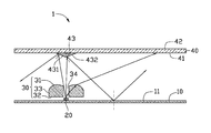
- FIGURE shows a cross sectional view of an LED light source module in accordance with an embodiment of the present disclosure.
- an LED light source module 1 in accordance with an embodiment of the present disclosure includes a base 10 , an LED light source 20 located on the base 10 , an optical lens 30 located on a light path of the LED light source 20 and a diffusion plate 40 located above the optical lens 30 .
- the LED light source module 1 is a planar light source which is used to illuminate a planar display device such a liquid crystal display (LCD) or a sign box.
- LCD liquid crystal display
- the base 10 is a thin plate, and includes an upper surface 11 .
- the upper surface 11 is reflective and can reflect light impinging thereon, whereby the light which impinges on the upper surface 11 can be reflected by the upper surface 11 to project upwardly to an area above the upper surface 11 .
- the upper surface 11 can be a smooth flat surface or an uneven surface.
- the LED light source 20 is located on the upper surface 11 of the base 10 , and electrically connected with the base 10 .
- the LED light source 20 is an LED package, and a light output surface of the LED light source 20 remotes from the base 10 .
- the optical lens 30 is located over the right top of the LED light source 20 , and spaced from the LED light source 20 .
- the optical lens 30 includes a top surface 31 , a bottom surface 32 opposite to the top surface 31 and a lateral surface 33 connecting the top surface 31 and the bottom surface 32 .
- the top surface 31 faces the diffusion plate 40
- the bottom surface 32 faces the LED light source 20 .
- the optical lens 30 defines a through hole 34 , and the through hole 34 penetrates through a middle of the optical lens 30 from the top surface 31 to the bottom surface 32 of the optical lens 30 .
- the top surface 31 is a curved surface
- the bottom surface 32 is a flat surface
- the lateral surface 33 is perpendicular to the bottom surface 32 .
- the through hole 34 right faces the light output surface of the LED light source 20 , and a bore size of the through hole 34 is greater than a width of the LED light source 20 .
- the diffusion plate 40 is a thin plate, and includes a light input surface 41 and a light output surface 42 opposite to the light input surface 41 .
- a reflecting body 43 is protruded from the light input surface 41 of the diffusion plate 40 toward the through hole 34 of the optical lens 30 .
- a projecting area of the reflecting body 43 on the optical lens 30 is greater than an area of a traversal cross-section of the through hole 34 .
- a longitudinal cross-section of the reflecting body 43 is triangular.
- the reflecting body 43 includes a first reflecting surface 431 on the left side and a second reflecting surface 432 on the right side, and the first reflecting surface 431 and the second reflecting surface 432 both face the through hole 34 .
- the first and second reflecting surfaces 431 , 432 are flat surfaces and inclined relative to the diffusion plate 40 and intersect each other at a point which is aligned with a center of the LED light source 20 and a center of the through hole 34 .
- the first reflecting surface 431 and the second reflecting surface 432 are reflective and can reflect light impinging thereon.
- the light impinging on the first reflecting surface 431 is reflected thereby toward the left area of the upper surface 11 of the base 10
- the light impinging on the second reflecting surface 432 is reflected thereby toward the right area of the upper surface 11 of the base 10 .
- the first reflecting surface 431 and the second reflecting surface 432 can be cambered surfaces.
- one part of the light emitted from the LED light source 20 runs through the through hole 34 of the optical lens 30 , and travels toward the first reflecting surface 431 and the second reflecting surface 432 of the diffusion plate 40 , and is reflected thereby toward the upper surface 11 of the base 10 .
- This part of light is then reflected by the base 10 toward the light input surface 41 of the diffusion plate 40 , and finally outputs to external environment from the light output surface 42 .
- the other part of the light travels toward an interior of the optical lens 30 , and is refracted by the optical lens 30 toward the light input surface 41 of the diffusion plate 40 , finally outputs to external environment from the light output surface 42 .
- the light intensity at the right top of the LED light source module 1 is weaker, and the light intensity of the peripheral area is stronger, whereby the light output of the LED light source module 1 is more uniform.
- the LED light source module 1 can be used as a backlight module or a lamp, and the light output of the backlight module or the lamp is more uniform.
Landscapes
- Engineering & Computer Science (AREA)
- General Engineering & Computer Science (AREA)
- Physics & Mathematics (AREA)
- Microelectronics & Electronic Packaging (AREA)
- Optics & Photonics (AREA)
- Planar Illumination Modules (AREA)
- Led Device Packages (AREA)
Abstract
Description
Claims (13)
Applications Claiming Priority (3)
| Application Number | Priority Date | Filing Date | Title |
|---|---|---|---|
| TW102136300 | 2013-10-08 | ||
| TW102136300A | 2013-10-08 | ||
| TW102136300A TW201514424A (en) | 2013-10-08 | 2013-10-08 | Light emitting diode light source module |
Publications (2)
| Publication Number | Publication Date |
|---|---|
| US20150098226A1 US20150098226A1 (en) | 2015-04-09 |
| US9243781B2 true US9243781B2 (en) | 2016-01-26 |
Family
ID=52776796
Family Applications (1)
| Application Number | Title | Priority Date | Filing Date |
|---|---|---|---|
| US14/103,859 Expired - Fee Related US9243781B2 (en) | 2013-10-08 | 2013-12-12 | Light emitting diode light source module having uniform illumination |
Country Status (2)
| Country | Link |
|---|---|
| US (1) | US9243781B2 (en) |
| TW (1) | TW201514424A (en) |
Families Citing this family (2)
| Publication number | Priority date | Publication date | Assignee | Title |
|---|---|---|---|---|
| TWI580902B (en) * | 2013-08-07 | 2017-05-01 | 鴻海精密工業股份有限公司 | Light emitting diode light source module |
| TWI580894B (en) * | 2013-09-18 | 2017-05-01 | 鴻海精密工業股份有限公司 | Lens |
Citations (7)
| Publication number | Priority date | Publication date | Assignee | Title |
|---|---|---|---|---|
| US5335157A (en) * | 1992-01-07 | 1994-08-02 | Whelen Technologies, Inc. | Anti-collision light assembly |
| US6547423B2 (en) * | 2000-12-22 | 2003-04-15 | Koninklijke Phillips Electronics N.V. | LED collimation optics with improved performance and reduced size |
| US20070297179A1 (en) * | 2006-06-27 | 2007-12-27 | Cree, Inc. | Efficient emitting LED package and method for efficiently emitting light |
| US7349163B2 (en) * | 2001-12-06 | 2008-03-25 | Fraen Corporation S.R.L. | High-heat-dissipation lighting module |
| US8556445B2 (en) * | 2010-06-02 | 2013-10-15 | Sharp Kabushiki Kaisha | Lighting device, display device and television device |
| US20150009679A1 (en) * | 2012-02-10 | 2015-01-08 | Enplas Corporation | Beam-control member and illumination device |
| US20150043217A1 (en) * | 2013-08-07 | 2015-02-12 | Hon Hai Precision Industry Co., Ltd. | Light emitting diode light source module having uniform illumination |
-
2013
- 2013-10-08 TW TW102136300A patent/TW201514424A/en unknown
- 2013-12-12 US US14/103,859 patent/US9243781B2/en not_active Expired - Fee Related
Patent Citations (7)
| Publication number | Priority date | Publication date | Assignee | Title |
|---|---|---|---|---|
| US5335157A (en) * | 1992-01-07 | 1994-08-02 | Whelen Technologies, Inc. | Anti-collision light assembly |
| US6547423B2 (en) * | 2000-12-22 | 2003-04-15 | Koninklijke Phillips Electronics N.V. | LED collimation optics with improved performance and reduced size |
| US7349163B2 (en) * | 2001-12-06 | 2008-03-25 | Fraen Corporation S.R.L. | High-heat-dissipation lighting module |
| US20070297179A1 (en) * | 2006-06-27 | 2007-12-27 | Cree, Inc. | Efficient emitting LED package and method for efficiently emitting light |
| US8556445B2 (en) * | 2010-06-02 | 2013-10-15 | Sharp Kabushiki Kaisha | Lighting device, display device and television device |
| US20150009679A1 (en) * | 2012-02-10 | 2015-01-08 | Enplas Corporation | Beam-control member and illumination device |
| US20150043217A1 (en) * | 2013-08-07 | 2015-02-12 | Hon Hai Precision Industry Co., Ltd. | Light emitting diode light source module having uniform illumination |
Also Published As
| Publication number | Publication date |
|---|---|
| US20150098226A1 (en) | 2015-04-09 |
| TW201514424A (en) | 2015-04-16 |
Similar Documents
| Publication | Publication Date | Title |
|---|---|---|
| US8979328B2 (en) | Optical lens and lighting device having same | |
| US20150009680A1 (en) | Lens and light emitting element using the same | |
| US20200159071A1 (en) | Back light unit and display device having the same | |
| US9188309B2 (en) | Direct type backlight module structure | |
| US20140177235A1 (en) | Optical lens and lighting device having the same | |
| CN101418930A (en) | Area source device for LED | |
| US9804374B2 (en) | Lens and light-emitting device employing same | |
| US20150184832A1 (en) | Optical lens assembly and light source module having the same | |
| CN104776344B (en) | LED light bar, backlight and display device | |
| US7267469B2 (en) | Compact lighting system and display device | |
| US9249938B2 (en) | Light emitting diode light source module having uniform illumination | |
| US9115866B2 (en) | LED unit with rectangular lens | |
| US9086593B2 (en) | LED unit and display incoporating the same | |
| US9243781B2 (en) | Light emitting diode light source module having uniform illumination | |
| CN104698677A (en) | Optical element and light emitting device including the same | |
| US9140827B2 (en) | Lens, LED light source unit having the lens and LED light source module incorporating the unit | |
| TW201708847A (en) | Lens and light-emitting device having same | |
| KR102092697B1 (en) | Lighting device | |
| US9476572B2 (en) | Optical lens assembly and light source module having the same | |
| US20150062964A1 (en) | Led module with light guiding plate | |
| US20150043197A1 (en) | Planar lighting device using light emitting diodes | |
| US20130201719A1 (en) | Front light module | |
| KR20140077292A (en) | Dfusion-light emitting element, led array unit having the same, and back light assembly having the same | |
| TWI616687B (en) | Light-emitting device and illuminating device, display device and electronic device using the same | |
| TW201539047A (en) | Lens and direct type light source module |
Legal Events
| Date | Code | Title | Description |
|---|---|---|---|
| AS | Assignment |
Owner name: HON HAI PRECISION INDUSTRY CO., LTD., TAIWAN Free format text: ASSIGNMENT OF ASSIGNORS INTEREST;ASSIGNOR:CHEN, PO-CHOU;REEL/FRAME:033459/0922 Effective date: 20131210 |
|
| STCF | Information on status: patent grant |
Free format text: PATENTED CASE |
|
| FEPP | Fee payment procedure |
Free format text: MAINTENANCE FEE REMINDER MAILED (ORIGINAL EVENT CODE: REM.); ENTITY STATUS OF PATENT OWNER: LARGE ENTITY |
|
| LAPS | Lapse for failure to pay maintenance fees |
Free format text: PATENT EXPIRED FOR FAILURE TO PAY MAINTENANCE FEES (ORIGINAL EVENT CODE: EXP.); ENTITY STATUS OF PATENT OWNER: LARGE ENTITY |
|
| STCH | Information on status: patent discontinuation |
Free format text: PATENT EXPIRED DUE TO NONPAYMENT OF MAINTENANCE FEES UNDER 37 CFR 1.362 |
|
| FP | Lapsed due to failure to pay maintenance fee |
Effective date: 20200126 |