US9239804B2 - Back-off mechanism for a peripheral page request log - Google Patents

Back-off mechanism for a peripheral page request log Download PDF

Info

Publication number
US9239804B2
US9239804B2 US14/045,701 US201314045701A US9239804B2 US 9239804 B2 US9239804 B2 US 9239804B2 US 201314045701 A US201314045701 A US 201314045701A US 9239804 B2 US9239804 B2 US 9239804B2
Authority
US
United States
Prior art keywords
ppr
peripheral
response
log
completion message
Prior art date
Legal status (The legal status is an assumption and is not a legal conclusion. Google has not performed a legal analysis and makes no representation as to the accuracy of the status listed.)
Active, expires
Application number
US14/045,701
Other versions
US20150100818A1 (en
Inventor
Andrew Kegel
Jimshed Mirza
Paul Blinzer
Philip Ng
Current Assignee (The listed assignees may be inaccurate. Google has not performed a legal analysis and makes no representation or warranty as to the accuracy of the list.)
ATI Technologies ULC
Advanced Micro Devices Inc
Original Assignee
Advanced Micro Devices Inc
Priority date (The priority date is an assumption and is not a legal conclusion. Google has not performed a legal analysis and makes no representation as to the accuracy of the date listed.)
Filing date
Publication date
Application filed by Advanced Micro Devices Inc filed Critical Advanced Micro Devices Inc
Priority to US14/045,701 priority Critical patent/US9239804B2/en
Assigned to ATI TECHNOLOGIES ULC reassignment ATI TECHNOLOGIES ULC ASSIGNMENT OF ASSIGNORS INTEREST (SEE DOCUMENT FOR DETAILS). Assignors: MIRZA, JIMSHED, NG, PHILIP
Assigned to ADVANCED MICRO DEVICES, INC. reassignment ADVANCED MICRO DEVICES, INC. ASSIGNMENT OF ASSIGNORS INTEREST (SEE DOCUMENT FOR DETAILS). Assignors: BLINZER, PAUL, KEGEL, ANDREW
Publication of US20150100818A1 publication Critical patent/US20150100818A1/en
Application granted granted Critical
Publication of US9239804B2 publication Critical patent/US9239804B2/en
Active legal-status Critical Current
Adjusted expiration legal-status Critical

Links

Images

Classifications

    • GPHYSICS
    • G06COMPUTING; CALCULATING OR COUNTING
    • G06FELECTRIC DIGITAL DATA PROCESSING
    • G06F13/00Interconnection of, or transfer of information or other signals between, memories, input/output devices or central processing units
    • GPHYSICS
    • G06COMPUTING; CALCULATING OR COUNTING
    • G06FELECTRIC DIGITAL DATA PROCESSING
    • G06F13/00Interconnection of, or transfer of information or other signals between, memories, input/output devices or central processing units
    • G06F13/38Information transfer, e.g. on bus
    • G06F13/382Information transfer, e.g. on bus using universal interface adapter
    • G06F13/385Information transfer, e.g. on bus using universal interface adapter for adaptation of a particular data processing system to different peripheral devices
    • GPHYSICS
    • G06COMPUTING; CALCULATING OR COUNTING
    • G06FELECTRIC DIGITAL DATA PROCESSING
    • G06F11/00Error detection; Error correction; Monitoring
    • G06F11/07Responding to the occurrence of a fault, e.g. fault tolerance
    • G06F11/0703Error or fault processing not based on redundancy, i.e. by taking additional measures to deal with the error or fault not making use of redundancy in operation, in hardware, or in data representation
    • G06F11/0706Error or fault processing not based on redundancy, i.e. by taking additional measures to deal with the error or fault not making use of redundancy in operation, in hardware, or in data representation the processing taking place on a specific hardware platform or in a specific software environment
    • G06F11/073Error or fault processing not based on redundancy, i.e. by taking additional measures to deal with the error or fault not making use of redundancy in operation, in hardware, or in data representation the processing taking place on a specific hardware platform or in a specific software environment in a memory management context, e.g. virtual memory or cache management
    • GPHYSICS
    • G06COMPUTING; CALCULATING OR COUNTING
    • G06FELECTRIC DIGITAL DATA PROCESSING
    • G06F11/00Error detection; Error correction; Monitoring
    • G06F11/07Responding to the occurrence of a fault, e.g. fault tolerance
    • G06F11/0703Error or fault processing not based on redundancy, i.e. by taking additional measures to deal with the error or fault not making use of redundancy in operation, in hardware, or in data representation
    • G06F11/0706Error or fault processing not based on redundancy, i.e. by taking additional measures to deal with the error or fault not making use of redundancy in operation, in hardware, or in data representation the processing taking place on a specific hardware platform or in a specific software environment
    • G06F11/0745Error or fault processing not based on redundancy, i.e. by taking additional measures to deal with the error or fault not making use of redundancy in operation, in hardware, or in data representation the processing taking place on a specific hardware platform or in a specific software environment in an input/output transactions management context
    • GPHYSICS
    • G06COMPUTING; CALCULATING OR COUNTING
    • G06FELECTRIC DIGITAL DATA PROCESSING
    • G06F11/00Error detection; Error correction; Monitoring
    • G06F11/07Responding to the occurrence of a fault, e.g. fault tolerance
    • G06F11/0703Error or fault processing not based on redundancy, i.e. by taking additional measures to deal with the error or fault not making use of redundancy in operation, in hardware, or in data representation
    • G06F11/0793Remedial or corrective actions
    • GPHYSICS
    • G06COMPUTING; CALCULATING OR COUNTING
    • G06FELECTRIC DIGITAL DATA PROCESSING
    • G06F12/00Accessing, addressing or allocating within memory systems or architectures
    • GPHYSICS
    • G06COMPUTING; CALCULATING OR COUNTING
    • G06FELECTRIC DIGITAL DATA PROCESSING
    • G06F12/00Accessing, addressing or allocating within memory systems or architectures
    • G06F12/02Addressing or allocation; Relocation
    • G06F12/08Addressing or allocation; Relocation in hierarchically structured memory systems, e.g. virtual memory systems
    • G06F12/10Address translation
    • G06F12/1009Address translation using page tables, e.g. page table structures
    • GPHYSICS
    • G06COMPUTING; CALCULATING OR COUNTING
    • G06FELECTRIC DIGITAL DATA PROCESSING
    • G06F12/00Accessing, addressing or allocating within memory systems or architectures
    • G06F12/02Addressing or allocation; Relocation
    • G06F12/08Addressing or allocation; Relocation in hierarchically structured memory systems, e.g. virtual memory systems
    • G06F12/10Address translation
    • G06F12/1081Address translation for peripheral access to main memory, e.g. direct memory access [DMA]
    • YGENERAL TAGGING OF NEW TECHNOLOGICAL DEVELOPMENTS; GENERAL TAGGING OF CROSS-SECTIONAL TECHNOLOGIES SPANNING OVER SEVERAL SECTIONS OF THE IPC; TECHNICAL SUBJECTS COVERED BY FORMER USPC CROSS-REFERENCE ART COLLECTIONS [XRACs] AND DIGESTS
    • Y02TECHNOLOGIES OR APPLICATIONS FOR MITIGATION OR ADAPTATION AGAINST CLIMATE CHANGE
    • Y02DCLIMATE CHANGE MITIGATION TECHNOLOGIES IN INFORMATION AND COMMUNICATION TECHNOLOGIES [ICT], I.E. INFORMATION AND COMMUNICATION TECHNOLOGIES AIMING AT THE REDUCTION OF THEIR OWN ENERGY USE
    • Y02D10/00Energy efficient computing, e.g. low power processors, power management or thermal management

Definitions

  • the present embodiments relate generally to management of peripherals in computing systems, and more specifically to managing address translation service requests and/or peripheral page requests.
  • An I/O memory management unit stores peripheral page requests (PPRs) from peripherals in a PPR log.
  • PPRs peripheral page requests
  • PPR log When a large number of peripherals generates PPRs, overflow of the PPR log becomes a risk. Overflow of the PPR log causes PPRs to be dropped, resulting in a loss of system state that can make the system unstable. Also, pausing I/O activity to avoid overflow will degrade system performance and may cause system failure.
  • a method of managing requests from peripherals in a computer system is performed in an IOMMU in the computer system.
  • a PPR is received from a peripheral.
  • a completion message is sent to the peripheral indicating that the PPR is complete and the PPR is discarded without queuing the PPR in the PPR log.
  • an IOMMU includes a PPR log to store PPRs received from peripherals.
  • the IOMMU also includes response generation logic to generate a completion message directed to a respective peripheral, in response to a determination that a criterion regarding an available capacity of the PPR log is satisfied.
  • the completion message indicates that a PPR from the respective peripheral that has not been stored in the PPR log is complete.
  • FIGS. 1A and 1B are block diagrams of computer systems in accordance with some embodiments.
  • FIG. 2 is a block diagram of a circular buffer used to implement a log in an IOMMU in accordance with some embodiments.
  • FIG. 3A is a timeline showing a sequence of requests and responses between an IOMMU and a peripheral.
  • FIGS. 3B-3D are timelines showing sequences of requests and responses between an IOMMU and a peripheral for situations in which a PPR log does not have enough space to store an incoming PPR, in accordance with some embodiments.
  • FIG. 4 is a block diagram of a portion of an IOMMU in accordance with some embodiments.
  • FIGS. 5A and 5B are flowcharts showing methods of managing requests from peripherals in accordance with some embodiments.
  • FIGS. 5C and 5D are flowcharts showing methods of operating a peripheral coupled to an IOMMU in accordance with some embodiments
  • FIG. 1A is a block diagram of a computer system 100 A in accordance with some embodiments.
  • the computer system 100 A includes one or more CPUs 102 , memory 106 , and peripherals 114 .
  • the one or more CPUs 102 may each include one or more processor cores, each of which executes one or more threads.
  • the memory 106 includes main memory and may include one or more levels of cache memory. (The one or more CPUs 102 may also include one or more levels of cache memory.)
  • the main memory is implemented in dynamic random access memory (DRAM) and the one or more levels of cache memory are implemented in static random access memory (SRAM).
  • Examples of peripherals 114 include, but are not limited to, network interface cards (NICs), other input/output (I/O) devices, and storage devices (e.g., hard-disk drives, solid-state drives such as flash drives, etc.).
  • NICs network interface cards
  • I/O input/output
  • storage devices e.g., hard-disk
  • a memory controller 104 couples the one or more CPUs 102 to the memory 106 , thereby providing the one or more CPUs 102 with access to the memory 106 .
  • the peripherals 114 are coupled to an input/output memory management unit (IOMMU) 108 , which is coupled to the memory controller 104 .
  • the IOMMU 108 and memory controller 104 thus couple the peripherals 114 to the one or more CPUs 102 and to the memory 106 .
  • the IOMMU 108 may also be referred to, for example, as a peripheral MMU, a system MMU, a translation agent system, or virtualization technology for directed I/O (Vt-d).
  • the IOMMU 108 communicates with the peripherals 114 in accordance with the Peripheral Component Interconnect Express (PCIe) protocol, through respective PCIe links.
  • PCIe Peripheral Component Interconnect Express
  • the IOMMU 108 performs address translation for the peripherals 114 : it translates virtual addresses provided by the peripherals 114 into physical addresses in the memory 106 .
  • the peripherals 114 may use these physical addresses to perform direct memory access (DMA) in the memory 106 , through the IOMMU 108 . If a peripheral 114 requests address translation for a page of memory that is not available in the memory 106 , the result is a page fault.
  • the peripheral 114 responds to the page fault by issuing a peripheral page request (PPR) requesting allocation of the page.
  • PPRs are stored in a PPR log 110 in the IOMMU 108 before being provided to the one or more CPUs 102 (e.g., as interrupts).
  • the software runs on the one or more CPUs 102 then processes the PPRs.
  • the software allocates a requested page by bringing it into the memory 106 from a peripheral storage device (e.g., a hard-disk drive or solid-state drive).
  • a command (CMD) log 112 in the IOMMU 108 stores responses to PPRs; the IOMMU 108 provides these responses to respective peripherals 114 .
  • the PPR log 110 and command log 112 may also be referred to as a PPR queue and command queue, respectively.
  • While the PPR log 110 and command log 112 are shown as being situated in the IOMMU 108 , entries in the PPR log 110 and/or command log 112 may be stored in the memory 106 (e.g., in main memory).
  • the IOMMU 108 includes registers that store pointers to the entries along with other information that defines the PPR log 110 and/or command log 112 .
  • the PPR log 110 and command log 112 may each be implemented as a circular buffer 200 ( FIG. 2 ) defined by values stored in registers in the IOMMU 108 and having entries stored in the memory 106 (e.g., in main memory). Because of the presence of these registers in the IOMMU 108 , the PPR log 110 and command log 112 are considered to be part of the IOMMU 108 , even with the entries being stored in the memory 106 .
  • the memory controller 104 is integrated with the one or more CPU(s) 102 , such that it is situated on the same semiconductor die (and thus the same chip) as the one or more CPU(s) 102 .
  • the memory controller 104 may be situated on a separate chip from the one or more CPU(s) 102 .
  • the IOMMU 108 may be situated on the same chip as the memory controller 104 and/or the one or more CPU(s) 102 , or on a different chip.
  • FIG. 1B is a block diagram of another computer system 100 B in accordance with some embodiments.
  • a first group of peripherals 114 is coupled to a first IOMMU 108 (e.g., through respective PCIe links) and a second group of peripherals 114 is coupled to a second IOMMU 108 (e.g., through respective PCIe links).
  • the first and second IOMMUs 108 are coupled to the memory controller 104 and thereby to the one or more CPUs 102 and the memory 106 .
  • the first and second IOMMUs 108 each include a PPR log 110 and a command log 112 .
  • the computer systems 100 A and 100 B are merely examples of computer systems that use IOMMUs 108 ; other examples are possible.
  • a computer system may include more than two IOMMUs 108 , each coupled to a respective group of peripherals 114 and including a PPR log 110 and a command log 112 .
  • Each IOMMU 108 may be coupled to respective peripherals 114 through an I/O hub, which may include integrated peripherals 114 .
  • the peripherals 114 coupled to an IOMMU 108 in a system such as the system 100 A or 100 B may number in the thousands or tens of thousands, in accordance with some embodiments.
  • PCIe theoretically allows for 65,536 peripherals 114 . With so many peripherals 114 potentially generating PPRs, overflow of the PPR log 110 becomes a risk.
  • FIG. 2 is a block diagram of a circular buffer 200 used to implement a PPR log 110 or a command log 112 ( FIGS. 1A-1B ) in accordance with some embodiments.
  • Register fields 202 for the circular buffer 200 include a tail pointer register field 202 - 1 to store a tail pointer for the circular buffer 200 , a base address register field 202 - 2 to store a base address of the circular buffer 200 , a size register field 202 - 3 to store a size of the circular buffer 200 , and a head pointer register field 202 - 4 to store a head pointer for the circular buffer 200 .
  • a plurality of entries 204 (e.g., entries 204 - 0 through 204 - 7 ) in the circular buffer 200 are stored in the memory 106 (e.g., in main memory).
  • the base address is the address of a first entry 204 - 0 or portion thereof.
  • the entries 204 - 0 through 204 - 7 are indexed by offsets from the first entry 204 - 0 , such that the base address plus the size is the address of the last entry 204 - 7 .
  • each entry is 128 bits (i.e., 16 bytes) and the offsets are multiples of 16 (e.g., the index for entry 204 - 0 is +00, the index for entry 204 - 1 is +16, and the index for entry 204 - 7 is +112).
  • the circular buffer is a 128-byte buffer. In general, however, the size and number of entries 204 , and thus the overall size of the circular buffer 200 , various for different implementations.
  • the head pointer points to the first valid entry 204 and the tail pointer points to the first invalid (i.e., empty) entry 204 .
  • the head pointer register field 202 - 4 thus stores the index for the first valid entry 204 and the tail pointer register field 202 - 1 thus stores the index for the first invalid entry 204 .
  • the circular buffer 200 currently has three valid entries: entries 204 - 2 , 204 - 3 , and 204 - 4 .
  • the head pointer points to entry 204 - 2 , which is the first valid entry 204 .
  • the tail pointer points to entry 204 - 5 , which is the first invalid entry.
  • FIG. 2 merely illustrates one example of a pointer convention for a circular buffer; other examples are possible.
  • the register fields 202 are included in one or more registers in an IOMMU 108 . Two or more of the register fields 202 may be in the same register. Alternatively, each of the register fields 202 may be in a separate register.
  • the IOMMU 108 When the IOMMU 108 creates a new entry in the PPR log 110 or command log 112 , it writes to the entry 204 to which the tail pointer points and then increments the tail pointer (wrapping around as necessary). If incrementing the tail pointer would cause the tail pointer to equal the head pointer (i.e., would cause the value in the tail pointer register field 202 - 1 to equal the value in the head pointer register field 202 - 4 ), then the circular buffer 200 is full. Adding another entry 204 when the circular buffer 200 is full would result in overflow.
  • the variables 206 correspond to the register fields 202 and include, for example, a tail pointer variable 206 - 1 , base address variable 206 - 2 , size variable 206 - 3 , and head pointer variable 206 - 4 .
  • the software when the software reads, and thus consumes, an entry 204 , it consumes the entry at the head of the circular buffer 204 (i.e., the first valid entry 204 ), as identified by the head pointer variable 206 - 4 . For example, it consumes entry 204 - 2 .
  • the software increments the head pointer variable 206 - 4 and writes the incremented value of the head pointer variable 206 - 4 to the head pointer register field 202 - 4 .
  • the head pointer register field 202 - 4 would then store a pointer to the entry 204 - 3 , as would the head pointer variable 206 - 4 .
  • entries will be lost and the software will not be able to process the lost entries. For example, if the circular buffer 200 is a PPR log 110 , overflow results in loss of PPRs from respective peripherals 114 , and thus loss of system state.
  • FIG. 3A is a timeline showing a sequence of request and response messages between an IOMMU 108 and a peripheral 114 .
  • the peripheral 114 sends an address translation service (ATS) request 302 to the IOMMU 108 , requesting translation of a virtual address for a page (or other unit of space in memory) to a physical address.
  • the IOMMU 108 responds with an ATS response 304 denying access to the virtual address and thus indicating that the virtual address is unavailable (e.g., because there is no corresponding physical address in the memory 106 , FIG. 1 ).
  • the ATS response 304 specifies that a write-access variable IW equals zero and that a read-access variable IR equals zero. The unavailability of the virtual address results in a page fault.
  • the peripheral 114 then sends a page request interface (PRI) request 306 to the IOMMU 108 .
  • the PRI request 306 conveys a PPR 308 to the IOMMU 108 requesting allocation of the page in the memory 106 ( FIG. 1 ).
  • the IOMMU 108 stores the PPR 308 in the PPR log 110 and subsequently provides the PPR 308 to the CPU 102 .
  • Software running on the CPU 102 allocates the requested page in the memory 106 and sends an allocation message 310 to the IOMMU 108 indicating that the requested page has been allocated.
  • the allocation message 310 is stored in the command log 112 and then sent on to the peripheral 114 in a PRI response 312 .
  • the PRI response 312 indicates that the PRI request 306 was successful.
  • the PRI response 312 prompts the peripheral 114 to send an ATS request 314 to the IOMMU 108 .
  • the ATS request 314 is a repeat of the ATS request 302 and requests attributes of the newly allocated page.
  • the IOMMU 108 responds with an ATS response 316 that provides the requested attributes.
  • the ATS response 316 provides the requested address translation (e.g., the physical address of the page) and allowed degree of access to the page.
  • FIG. 3A assumes that space is available in the PPR log 110 to store the PPR 308 .
  • FIG. 3B is a timeline showing a sequence of request and response messages between an IOMMU 108 and a peripheral 114 for a situation in which the PPR log 110 does not have enough space to store an incoming PPR from the peripheral 114 , in accordance with some embodiments.
  • the PPR log 110 is full.
  • the PPR log 110 is not full, but all remaining entries in the PPR log 110 are reserved for other requests (e.g., for stop marker messages).
  • the ATS request 302 , ATS response 304 , and PRI request 306 are communicated between the peripheral 114 and IOMMU 108 in the manner described for FIG. 3A .
  • the PPR in the PRI request 306 is not stored in the PPR log 110 . Instead, the IOMMU 108 sends a PRI response 330 to the peripheral 114 .
  • the PRI response 330 indicates that the PRI request 306 is complete and that the PPR in the PRI request 306 therefore has been processed, even though the PPR actually has not been processed.
  • the peripheral 114 sends an ATS request 314 to the IOMMU 108 .
  • the ATS request 314 is a repeat of the ATS request 302 , as described for FIG. 3A .
  • the IOMMU 108 responds with an ATS response 332 denying access to the requested page.
  • the ATS response 332 is a repeat of the ATS response 304 and prompts the peripheral 114 to send another PRI request 334 .
  • the IOMMU 108 sends a PRI response 336 to the peripheral 114 .
  • the PRI response 336 like the PRI response 330 , indicates that the PPR in the PRI request 334 has been processed, even though the PPR actually has not been processed, since it was never stored in the PPR log 110 .
  • ATS requests, ATS responses, PRI requests, and PRI responses continue to be sent back and forth in this sequence until an entry for the PPR becomes available in the PPR log 110 .
  • the sequence of FIG. 3B allows systems such as the system 100 A or 100 B to keep functioning without loss of system state when the PPR log 110 lacks capacity for storing received PPRs.
  • the back-and-forth traffic in the sequence of FIG. 3B contends with other traffic (e.g., DMA traffic) and consumes power.
  • FIG. 3C is a timeline showing another sequence of request and response messages between an IOMMU 108 and a peripheral 114 for a situation in which the PPR log 110 does not have enough space to store an incoming PPR from the peripheral 114 , in accordance with some embodiments.
  • the sequence of FIG. 3C reduces the back-and-forth traffic of FIG. 3B by introducing a delay between the PRI request 306 and PRI response 330 . (Subsequent PRI responses in the sequence are similarly delayed with respect to their corresponding PRI requests.) Sending of the PRI response 330 is delayed by a delay period 352 .
  • the delay period 352 is software programmable.
  • a PRI response delay queue 350 which is distinct from the PPR log 110 .
  • This information is used to generate the PRI response 330 and includes, for example, a device identifier for the peripheral 114 that sent the PRI request 306 and an index associated with the PRI request 306 (e.g., a page request group index).
  • the PRI response 330 is followed by the ATS request 314 , the ATS response 332 , and subsequent requests and responses.
  • the delay period 352 thus results in reduced power and increased bandwidth for other traffic, such as DMA traffic.
  • the back-and-forth traffic of FIG. 3B may also be reduced by introducing a delay between the ATS request 302 and ATS response 304 , as shown in FIG. 3D in accordance with some embodiments.
  • Sending of the ATS response 304 is delayed by a delay period 372 when the PPR log 110 does not have enough space to store an incoming PPR.
  • the delay period 372 is software programmable.
  • information regarding the ATS request 302 is stored in an ATS response delay queue 370 , which is distinct from the PPR log 110 and/or the queue 350 ( FIG. 3C ). This information is used to generate the ATS response 304 .
  • the ATS response 304 is followed by subsequent requests and responses, by analogy to FIG. 3B or 3 C.
  • both the delay period 352 ( FIG. 3C ) and the delay period 372 ( FIG. 3D ) are used to reduce back-and-forth traffic.
  • only one of the delay periods 352 and 372 is used.
  • FIG. 4 is a block diagram of a portion of an IOMMU 400 in accordance with some embodiments.
  • the IOMMU 400 is an example of an IOMMU 108 ( FIGS. 1A-1B ).
  • the IOMMU 400 includes an address translation module 414 for translating virtual addresses to physical addresses (e.g., by walking page tables and/or using a translation look-aside buffer) and a DMA module 416 for performing direct memory accesses.
  • the IOMMU 400 also includes response generation logic 402 for generating ATS responses and/or PRI responses (e.g., as shown in FIGS. 3A-3D ).
  • the response generation logic 402 includes a PPR log status monitor 404 to determine whether the available capacity of the PPR log 110 has become limited to a point that the response generation logic should generate the PRI responses 330 and 336 ( FIGS. 3B-3C ), implement the delay period 352 ( FIG. 3C ), and/or implement the delay period 372 ( FIG. 3D ).
  • the response generation logic 402 also includes a PRI response delay timer 406 for implementing the delay period 352 ( FIG. 3C ) and a PRI response delay queue 350 , as described with respect to FIG. 3C .
  • the response generation logic 402 also includes an ATS response delay timer 410 for implementing the delay period 372 ( FIG. 3D ) and an ATS response delay queue 370 , as described with respect to FIG. 3D .
  • the delay periods 352 and/or 372 may be cut short in response to a determination by the PPR log status monitor 404 that the available capacity of the PPR log 110 is sufficient to store an incoming PPR (e.g., as conveyed by a PRI message).
  • the PRI response delay queue 350 and/or the ATS response delay queue 370 may be implemented as circular buffers 200 ( FIG. 2 ).
  • the PRI response delay queue 350 stores information regarding multiple PPRs that are not queued in the PPR log 110 and for which corresponding PRI responses 330 and 336 are being delayed. If the PRI response delay queue 350 becomes full or nearly full, one or more entries may be drained from the PRI response delay queue 350 and the corresponding PRI responses 330 or 336 sent before expiration of their respective delay periods 352 ( FIG. 3C ). For example, it is determined that an available capacity of the PRI response delay queue 350 is less than, or less than or equal to, a threshold.
  • one or more PRI responses 330 carrying completion messages for respective PPRs are sent to respective peripherals 114 that issued the respective PPRs, without waiting for expiration of the respective delay periods 352 , and the information regarding the respective PPRs is deleted from the PRI response delay queue 350 .
  • the ATS response delay queue 370 may be drained in a similar manner when it becomes full or nearly full.
  • the IOMMU 400 includes an interface 418 for coupling the IOMMU 400 to the memory controller 104 ( FIGS. 1A-1B ) and interfaces 420 (e.g., PCIe interfaces) for coupling the IOMMU 400 to respective peripherals 114 ( FIGS. 1A-1B ).
  • interfaces 420 e.g., PCIe interfaces
  • FIG. 5A is a flowchart showing a method 500 of managing requests from peripherals 114 in accordance with some embodiments.
  • the method 500 is performed ( 502 ) in an IOMMU 108 ( FIGS. 1A-1B ).
  • the method 500 may be performed in an IOMMU 400 ( FIG. 4 ).
  • an ATS request 302 ( FIGS. 3A-3D ) for a page is received ( 504 ) from a peripheral 114 .
  • the requested page is not accessible (e.g., is not available in the memory 106 , FIG. 1 ).
  • an ATS response 304 ( FIG. 3A ) is sent ( 508 ) to the peripheral 114 denying access to the page.
  • sending of the ATS response 304 to the peripheral 114 is delayed ( 510 ) (e.g., in accordance with a specified delay period 372 , FIG. 3D ).
  • Information regarding the ATS request 302 may be stored during the delay in a queue (e.g., the ATS response delay queue 370 , FIGS. 3D and 4 ) that is distinct from the PPR log 110 .
  • sending of the ATS response 304 is delayed until the specified delay period 372 has expired ( 512 -Yes) (e.g., as shown in FIG.
  • the determination 514 may include determining that the available capacity of the PPR log 110 has become greater than, or greater than or equal to, a threshold.
  • the ATS response 304 is then sent ( 516 ) to the peripheral 114 , denying access to the page. The duration of the delay therefore may be less than the specified delay period 372 , as a result of the determination 514 .
  • the determination 514 is omitted from the method 500 , and sending of the ATS response is delayed until the specified delay period 372 expires ( 512 -Yes).
  • FIG. 5B is a flowchart showing a method 520 of managing requests from peripherals 114 in accordance with some embodiments.
  • the method 520 is performed ( 522 ) in an IOMMU 108 ( FIGS. 1A-1B ), such as the IOMMU 400 ( FIG. 4 ).
  • the method 520 may be performed in conjunction with the method 500 ( FIG. 5A ). For example, the method 520 may follow on from the method 500 .
  • a PPR is received ( 524 ) from a peripheral 114 (e.g., the peripheral 114 of the method 500 ).
  • receiving the PPR includes receiving ( 526 ) a PRI request 306 ( FIGS. 3A-3D ) from the peripheral 114 .
  • the PPR is stored ( 530 ) in the PPR log 110 .
  • sending the completion message includes sending ( 542 ) a PRI response message 330 ( FIGS. 3B and 3C ) to the peripheral 114 .
  • sending of the completion message is delayed ( 532 ) (e.g., in accordance with a specified delay period 352 , FIG. 3C ).
  • Information regarding the PPR may be stored ( 534 ) during the delay in a queue (e.g., the PRI response delay queue 350 , FIGS. 3C and 4 ) that is distinct from the PPR log 110 .
  • sending of the completion message is delayed until the specified delay period 352 has expired ( 536 -Yes) (e.g., as shown in FIG. 3C ) or until a determination is made ( 538 -No) that the criterion regarding the available capacity of the PPR log 110 is no longer satisfied.
  • the determination 538 may include determining that the available capacity of the PPR log 110 has become greater than, or greater than or equal to, a threshold. The duration of the delay therefore may be less than the specified delay period 352 , as a result of the determination 538 .
  • the determination 538 is omitted from the method 520 , and sending of the completion message is delayed until the specified delay period 352 expires ( 536 -Yes).
  • the completion message includes a code to indicate to the peripheral 114 that the PPR log 110 is unavailable, as determined by satisfaction of the criterion of the operation 528 .
  • FIGS. 5C and 5D are flowcharts showing respective methods 560 and 580 that illustrate examples of responses to this code, in accordance with some embodiments.
  • the PPR that the IOMMU 108 receives in the operation 524 ( FIG. 5B ) is initially sent ( 564 ) to the IOMMU 108 .
  • the peripheral 114 receives ( 566 ) the completion message sent in the operation 540 ( FIG. 5B ).
  • the completion message includes the code indicating that the PPR log 110 is unavailable.
  • the peripheral delays ( 568 ) sending a subsequent request (e.g., an ATS request 314 , FIGS. 3B-3C ) to the IOMMU 108 . This delay provides the same benefits as the delay periods 352 ( FIG. 3C) and 372 ( FIG. 3D ).
  • the PPR that the IOMMU 108 receives in the operation 524 ( FIG. 5B ) is initially sent ( 584 ) to the IOMMU 108 .
  • the PPR is associated with a first computational thread.
  • the peripheral 114 receives ( 566 ) the completion message, as described in the method 560 ( FIG. 5C ).
  • the peripheral 114 responds to the code by switching ( 586 ) to performance of a task associated with a second computational thread distinct from the first computational thread.
  • the method 580 avoids sending repeated requests and responses and allows forward progress to be made on the second computational thread.
  • the methods 500 , 520 , 560 and 580 avoid overflow of the PPR log 110 and preserve system state when the PPR log 110 becomes unavailable. Furthermore, the methods 500 , 520 , 560 and 580 achieve these results in hardware, and thus allow this functionality to be offloaded from the one or more CPUs 102 ( FIGS. 1A-1B ). While the methods 500 , 520 , 560 and 580 include a number of operations that appear to occur in a specific order, it should be apparent that the methods 500 , 520 , 560 and/or 580 can include more or fewer operations, some of which can be executed serially or in parallel. An order of two or more operations may be changed, performance of two or more operations may overlap, and two or more operations may be combined into a single operation.
  • Embodiments described herein may be implemented in computer hardware.
  • the methods 500 and 520 may be performed in hardware in an IOMMU 108
  • the methods 560 and 580 may be performed in hardware in a peripheral 114 .
  • embodiments described herein may be implemented in firmware or software.
  • a non-transitory computer-readable storage medium e.g., in a peripheral 114 , FIGS. 1A-1B

Abstract

A system and method of managing requests from peripherals in a computer system are provided. In the system and method, an input/output memory management unit (IOMMU) receives a peripheral page request (PPR) from a peripheral. In response to a determination that a criterion regarding an available capacity of a PPR log is satisfied, a completion message is sent to the peripheral indicating that the PPR is complete and the PPR is discarded without queuing the PPR in the PPR log.

Description

TECHNICAL FIELD
The present embodiments relate generally to management of peripherals in computing systems, and more specifically to managing address translation service requests and/or peripheral page requests.
BACKGROUND
An I/O memory management unit (IOMMU) stores peripheral page requests (PPRs) from peripherals in a PPR log. When a large number of peripherals generates PPRs, overflow of the PPR log becomes a risk. Overflow of the PPR log causes PPRs to be dropped, resulting in a loss of system state that can make the system unstable. Also, pausing I/O activity to avoid overflow will degrade system performance and may cause system failure.
SUMMARY OF ONE OR MORE EMBODIMENTS
In some embodiments, a method of managing requests from peripherals in a computer system is performed in an IOMMU in the computer system. In the method, a PPR is received from a peripheral. In response to a determination that a criterion regarding an available capacity of a PPR log is satisfied, a completion message is sent to the peripheral indicating that the PPR is complete and the PPR is discarded without queuing the PPR in the PPR log.
In some embodiments, an IOMMU includes a PPR log to store PPRs received from peripherals. The IOMMU also includes response generation logic to generate a completion message directed to a respective peripheral, in response to a determination that a criterion regarding an available capacity of the PPR log is satisfied. The completion message indicates that a PPR from the respective peripheral that has not been stored in the PPR log is complete.
BRIEF DESCRIPTION OF THE DRAWINGS
The present embodiments are illustrated by way of example and are not intended to be limited by the figures of the accompanying drawings.
FIGS. 1A and 1B are block diagrams of computer systems in accordance with some embodiments.
FIG. 2 is a block diagram of a circular buffer used to implement a log in an IOMMU in accordance with some embodiments.
FIG. 3A is a timeline showing a sequence of requests and responses between an IOMMU and a peripheral.
FIGS. 3B-3D are timelines showing sequences of requests and responses between an IOMMU and a peripheral for situations in which a PPR log does not have enough space to store an incoming PPR, in accordance with some embodiments.
FIG. 4 is a block diagram of a portion of an IOMMU in accordance with some embodiments.
FIGS. 5A and 5B are flowcharts showing methods of managing requests from peripherals in accordance with some embodiments.
FIGS. 5C and 5D are flowcharts showing methods of operating a peripheral coupled to an IOMMU in accordance with some embodiments
Like reference numerals refer to corresponding parts throughout the figures and specification.
DETAILED DESCRIPTION
Reference will now be made in detail to various embodiments, examples of which are illustrated in the accompanying drawings. In the following detailed description, numerous specific details are set forth in order to provide a thorough understanding of the disclosure. However, some embodiments may be practiced without these specific details. In other instances, well-known methods, procedures, components, and circuits have not been described in detail so as not to unnecessarily obscure aspects of the embodiments.
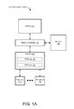
FIG. 1A is a block diagram of a computer system 100A in accordance with some embodiments. The computer system 100A includes one or more CPUs 102, memory 106, and peripherals 114. The one or more CPUs 102 may each include one or more processor cores, each of which executes one or more threads. The memory 106 includes main memory and may include one or more levels of cache memory. (The one or more CPUs 102 may also include one or more levels of cache memory.) In some embodiments, the main memory is implemented in dynamic random access memory (DRAM) and the one or more levels of cache memory are implemented in static random access memory (SRAM). Examples of peripherals 114 include, but are not limited to, network interface cards (NICs), other input/output (I/O) devices, and storage devices (e.g., hard-disk drives, solid-state drives such as flash drives, etc.).
A memory controller 104 couples the one or more CPUs 102 to the memory 106, thereby providing the one or more CPUs 102 with access to the memory 106.
The peripherals 114 are coupled to an input/output memory management unit (IOMMU) 108, which is coupled to the memory controller 104. The IOMMU 108 and memory controller 104 thus couple the peripherals 114 to the one or more CPUs 102 and to the memory 106. The IOMMU 108 may also be referred to, for example, as a peripheral MMU, a system MMU, a translation agent system, or virtualization technology for directed I/O (Vt-d). In some embodiments, the IOMMU 108 communicates with the peripherals 114 in accordance with the Peripheral Component Interconnect Express (PCIe) protocol, through respective PCIe links.
The IOMMU 108 performs address translation for the peripherals 114: it translates virtual addresses provided by the peripherals 114 into physical addresses in the memory 106. The peripherals 114 may use these physical addresses to perform direct memory access (DMA) in the memory 106, through the IOMMU 108. If a peripheral 114 requests address translation for a page of memory that is not available in the memory 106, the result is a page fault. The peripheral 114 responds to the page fault by issuing a peripheral page request (PPR) requesting allocation of the page. PPRs are stored in a PPR log 110 in the IOMMU 108 before being provided to the one or more CPUs 102 (e.g., as interrupts). Software running on the one or more CPUs 102 then processes the PPRs. The software allocates a requested page by bringing it into the memory 106 from a peripheral storage device (e.g., a hard-disk drive or solid-state drive). A command (CMD) log 112 in the IOMMU 108 stores responses to PPRs; the IOMMU 108 provides these responses to respective peripherals 114. The PPR log 110 and command log 112 may also be referred to as a PPR queue and command queue, respectively.
While the PPR log 110 and command log 112 are shown as being situated in the IOMMU 108, entries in the PPR log 110 and/or command log 112 may be stored in the memory 106 (e.g., in main memory). The IOMMU 108 includes registers that store pointers to the entries along with other information that defines the PPR log 110 and/or command log 112. For example, the PPR log 110 and command log 112 may each be implemented as a circular buffer 200 (FIG. 2) defined by values stored in registers in the IOMMU 108 and having entries stored in the memory 106 (e.g., in main memory). Because of the presence of these registers in the IOMMU 108, the PPR log 110 and command log 112 are considered to be part of the IOMMU 108, even with the entries being stored in the memory 106.
In some embodiments, the memory controller 104 is integrated with the one or more CPU(s) 102, such that it is situated on the same semiconductor die (and thus the same chip) as the one or more CPU(s) 102. Alternatively, the memory controller 104 may be situated on a separate chip from the one or more CPU(s) 102. The IOMMU 108 may be situated on the same chip as the memory controller 104 and/or the one or more CPU(s) 102, or on a different chip.
FIG. 1B is a block diagram of another computer system 100B in accordance with some embodiments. In the computer system 100B, a first group of peripherals 114 is coupled to a first IOMMU 108 (e.g., through respective PCIe links) and a second group of peripherals 114 is coupled to a second IOMMU 108 (e.g., through respective PCIe links). The first and second IOMMUs 108 are coupled to the memory controller 104 and thereby to the one or more CPUs 102 and the memory 106. The first and second IOMMUs 108 each include a PPR log 110 and a command log 112.
The computer systems 100A and 100B are merely examples of computer systems that use IOMMUs 108; other examples are possible. For example, a computer system may include more than two IOMMUs 108, each coupled to a respective group of peripherals 114 and including a PPR log 110 and a command log 112. Each IOMMU 108 may be coupled to respective peripherals 114 through an I/O hub, which may include integrated peripherals 114.
The peripherals 114 coupled to an IOMMU 108 in a system such as the system 100A or 100B may number in the thousands or tens of thousands, in accordance with some embodiments. For example, PCIe theoretically allows for 65,536 peripherals 114. With so many peripherals 114 potentially generating PPRs, overflow of the PPR log 110 becomes a risk.
FIG. 2 is a block diagram of a circular buffer 200 used to implement a PPR log 110 or a command log 112 (FIGS. 1A-1B) in accordance with some embodiments. Register fields 202 for the circular buffer 200 include a tail pointer register field 202-1 to store a tail pointer for the circular buffer 200, a base address register field 202-2 to store a base address of the circular buffer 200, a size register field 202-3 to store a size of the circular buffer 200, and a head pointer register field 202-4 to store a head pointer for the circular buffer 200. A plurality of entries 204 (e.g., entries 204-0 through 204-7) in the circular buffer 200 are stored in the memory 106 (e.g., in main memory). The base address is the address of a first entry 204-0 or portion thereof. The entries 204-0 through 204-7 are indexed by offsets from the first entry 204-0, such that the base address plus the size is the address of the last entry 204-7. In one example, each entry is 128 bits (i.e., 16 bytes) and the offsets are multiples of 16 (e.g., the index for entry 204-0 is +00, the index for entry 204-1 is +16, and the index for entry 204-7 is +112). In this example, the circular buffer is a 128-byte buffer. In general, however, the size and number of entries 204, and thus the overall size of the circular buffer 200, various for different implementations.
In some embodiments, the head pointer points to the first valid entry 204 and the tail pointer points to the first invalid (i.e., empty) entry 204. The head pointer register field 202-4 thus stores the index for the first valid entry 204 and the tail pointer register field 202-1 thus stores the index for the first invalid entry 204. In the example of FIG. 2, the circular buffer 200 currently has three valid entries: entries 204-2, 204-3, and 204-4. The head pointer points to entry 204-2, which is the first valid entry 204. The tail pointer points to entry 204-5, which is the first invalid entry. (FIG. 2 merely illustrates one example of a pointer convention for a circular buffer; other examples are possible.)
The register fields 202 are included in one or more registers in an IOMMU 108. Two or more of the register fields 202 may be in the same register. Alternatively, each of the register fields 202 may be in a separate register.
When the IOMMU 108 creates a new entry in the PPR log 110 or command log 112, it writes to the entry 204 to which the tail pointer points and then increments the tail pointer (wrapping around as necessary). If incrementing the tail pointer would cause the tail pointer to equal the head pointer (i.e., would cause the value in the tail pointer register field 202-1 to equal the value in the head pointer register field 202-4), then the circular buffer 200 is full. Adding another entry 204 when the circular buffer 200 is full would result in overflow.
Software running on the one or more CPUs 102 (FIGS. 1A and 1B) tracks variables 206 associated with the circular buffer 200. The variables 206 correspond to the register fields 202 and include, for example, a tail pointer variable 206-1, base address variable 206-2, size variable 206-3, and head pointer variable 206-4. In some embodiments, when the software reads, and thus consumes, an entry 204, it consumes the entry at the head of the circular buffer 204 (i.e., the first valid entry 204), as identified by the head pointer variable 206-4. For example, it consumes entry 204-2. The software then increments the head pointer variable 206-4 and writes the incremented value of the head pointer variable 206-4 to the head pointer register field 202-4. In the example of FIG. 2, the head pointer register field 202-4 would then store a pointer to the entry 204-3, as would the head pointer variable 206-4. If the circular buffer 200 overflows, however, then entries will be lost and the software will not be able to process the lost entries. For example, if the circular buffer 200 is a PPR log 110, overflow results in loss of PPRs from respective peripherals 114, and thus loss of system state.
FIG. 3A is a timeline showing a sequence of request and response messages between an IOMMU 108 and a peripheral 114. The peripheral 114 sends an address translation service (ATS) request 302 to the IOMMU 108, requesting translation of a virtual address for a page (or other unit of space in memory) to a physical address. The IOMMU 108 responds with an ATS response 304 denying access to the virtual address and thus indicating that the virtual address is unavailable (e.g., because there is no corresponding physical address in the memory 106, FIG. 1). For example, the ATS response 304 specifies that a write-access variable IW equals zero and that a read-access variable IR equals zero. The unavailability of the virtual address results in a page fault.
To recover from the page fault, the peripheral 114 then sends a page request interface (PRI) request 306 to the IOMMU 108. The PRI request 306 conveys a PPR 308 to the IOMMU 108 requesting allocation of the page in the memory 106 (FIG. 1). The IOMMU 108 stores the PPR 308 in the PPR log 110 and subsequently provides the PPR 308 to the CPU 102. Software running on the CPU 102 allocates the requested page in the memory 106 and sends an allocation message 310 to the IOMMU 108 indicating that the requested page has been allocated. The allocation message 310 is stored in the command log 112 and then sent on to the peripheral 114 in a PRI response 312. The PRI response 312 indicates that the PRI request 306 was successful.
The PRI response 312 prompts the peripheral 114 to send an ATS request 314 to the IOMMU 108. The ATS request 314 is a repeat of the ATS request 302 and requests attributes of the newly allocated page. The IOMMU 108 responds with an ATS response 316 that provides the requested attributes. For example, the ATS response 316 provides the requested address translation (e.g., the physical address of the page) and allowed degree of access to the page. For example, the ATS response may provide full access (e.g., IW=IR=1) or read-only access (e.g., IW=0, IR=1).
The example of FIG. 3A assumes that space is available in the PPR log 110 to store the PPR 308.
FIG. 3B is a timeline showing a sequence of request and response messages between an IOMMU 108 and a peripheral 114 for a situation in which the PPR log 110 does not have enough space to store an incoming PPR from the peripheral 114, in accordance with some embodiments. For example, the PPR log 110 is full. In another example, the PPR log 110 is not full, but all remaining entries in the PPR log 110 are reserved for other requests (e.g., for stop marker messages). In FIG. 3B, the ATS request 302, ATS response 304, and PRI request 306 are communicated between the peripheral 114 and IOMMU 108 in the manner described for FIG. 3A. The PPR in the PRI request 306, however, is not stored in the PPR log 110. Instead, the IOMMU 108 sends a PRI response 330 to the peripheral 114. The PRI response 330 indicates that the PRI request 306 is complete and that the PPR in the PRI request 306 therefore has been processed, even though the PPR actually has not been processed.
In response to the PRI response 330, the peripheral 114 sends an ATS request 314 to the IOMMU 108. The ATS request 314 is a repeat of the ATS request 302, as described for FIG. 3A. The IOMMU 108 responds with an ATS response 332 denying access to the requested page. The ATS response 332 is a repeat of the ATS response 304 and prompts the peripheral 114 to send another PRI request 334. In response, the IOMMU 108 sends a PRI response 336 to the peripheral 114. The PRI response 336, like the PRI response 330, indicates that the PPR in the PRI request 334 has been processed, even though the PPR actually has not been processed, since it was never stored in the PPR log 110. ATS requests, ATS responses, PRI requests, and PRI responses continue to be sent back and forth in this sequence until an entry for the PPR becomes available in the PPR log 110.
The sequence of FIG. 3B allows systems such as the system 100A or 100B to keep functioning without loss of system state when the PPR log 110 lacks capacity for storing received PPRs. However, the back-and-forth traffic in the sequence of FIG. 3B contends with other traffic (e.g., DMA traffic) and consumes power.
FIG. 3C is a timeline showing another sequence of request and response messages between an IOMMU 108 and a peripheral 114 for a situation in which the PPR log 110 does not have enough space to store an incoming PPR from the peripheral 114, in accordance with some embodiments. The sequence of FIG. 3C reduces the back-and-forth traffic of FIG. 3B by introducing a delay between the PRI request 306 and PRI response 330. (Subsequent PRI responses in the sequence are similarly delayed with respect to their corresponding PRI requests.) Sending of the PRI response 330 is delayed by a delay period 352. In some embodiments, the delay period 352 is software programmable. During the delay period 352, information regarding the PPR in the PRI request 306 is stored in a PRI response delay queue 350, which is distinct from the PPR log 110. This information is used to generate the PRI response 330 and includes, for example, a device identifier for the peripheral 114 that sent the PRI request 306 and an index associated with the PRI request 306 (e.g., a page request group index). The PRI response 330 is followed by the ATS request 314, the ATS response 332, and subsequent requests and responses.
The delay period 352 thus results in reduced power and increased bandwidth for other traffic, such as DMA traffic.
The back-and-forth traffic of FIG. 3B may also be reduced by introducing a delay between the ATS request 302 and ATS response 304, as shown in FIG. 3D in accordance with some embodiments. Sending of the ATS response 304 is delayed by a delay period 372 when the PPR log 110 does not have enough space to store an incoming PPR. In some embodiments, the delay period 372 is software programmable. During the delay period 372, information regarding the ATS request 302 is stored in an ATS response delay queue 370, which is distinct from the PPR log 110 and/or the queue 350 (FIG. 3C). This information is used to generate the ATS response 304. The ATS response 304 is followed by subsequent requests and responses, by analogy to FIG. 3B or 3C.
In some embodiments, both the delay period 352 (FIG. 3C) and the delay period 372 (FIG. 3D) are used to reduce back-and-forth traffic. Alternatively, only one of the delay periods 352 and 372 is used.
FIG. 4 is a block diagram of a portion of an IOMMU 400 in accordance with some embodiments. The IOMMU 400 is an example of an IOMMU 108 (FIGS. 1A-1B). In addition to the PPR log 110 and command log 112, the IOMMU 400 includes an address translation module 414 for translating virtual addresses to physical addresses (e.g., by walking page tables and/or using a translation look-aside buffer) and a DMA module 416 for performing direct memory accesses.
The IOMMU 400 also includes response generation logic 402 for generating ATS responses and/or PRI responses (e.g., as shown in FIGS. 3A-3D). The response generation logic 402 includes a PPR log status monitor 404 to determine whether the available capacity of the PPR log 110 has become limited to a point that the response generation logic should generate the PRI responses 330 and 336 (FIGS. 3B-3C), implement the delay period 352 (FIG. 3C), and/or implement the delay period 372 (FIG. 3D). In some embodiments, the response generation logic 402 also includes a PRI response delay timer 406 for implementing the delay period 352 (FIG. 3C) and a PRI response delay queue 350, as described with respect to FIG. 3C. In some embodiments, the response generation logic 402 also includes an ATS response delay timer 410 for implementing the delay period 372 (FIG. 3D) and an ATS response delay queue 370, as described with respect to FIG. 3D. In some embodiments, the delay periods 352 and/or 372 may be cut short in response to a determination by the PPR log status monitor 404 that the available capacity of the PPR log 110 is sufficient to store an incoming PPR (e.g., as conveyed by a PRI message). The PRI response delay queue 350 and/or the ATS response delay queue 370 may be implemented as circular buffers 200 (FIG. 2).
The PRI response delay queue 350 stores information regarding multiple PPRs that are not queued in the PPR log 110 and for which corresponding PRI responses 330 and 336 are being delayed. If the PRI response delay queue 350 becomes full or nearly full, one or more entries may be drained from the PRI response delay queue 350 and the corresponding PRI responses 330 or 336 sent before expiration of their respective delay periods 352 (FIG. 3C). For example, it is determined that an available capacity of the PRI response delay queue 350 is less than, or less than or equal to, a threshold. In response, one or more PRI responses 330 carrying completion messages for respective PPRs are sent to respective peripherals 114 that issued the respective PPRs, without waiting for expiration of the respective delay periods 352, and the information regarding the respective PPRs is deleted from the PRI response delay queue 350. The ATS response delay queue 370 may be drained in a similar manner when it becomes full or nearly full.
The IOMMU 400 includes an interface 418 for coupling the IOMMU 400 to the memory controller 104 (FIGS. 1A-1B) and interfaces 420 (e.g., PCIe interfaces) for coupling the IOMMU 400 to respective peripherals 114 (FIGS. 1A-1B).
FIG. 5A is a flowchart showing a method 500 of managing requests from peripherals 114 in accordance with some embodiments. The method 500 is performed (502) in an IOMMU 108 (FIGS. 1A-1B). For example, the method 500 may be performed in an IOMMU 400 (FIG. 4).
In the method 500, an ATS request 302 (FIGS. 3A-3D) for a page is received (504) from a peripheral 114. The requested page is not accessible (e.g., is not available in the memory 106, FIG. 1).
It is determined (506) whether a criterion regarding the available capacity of a PPR log 110 is satisfied. For example, it is determined whether the available capacity of the PPR log 110 is less than, or less than or equal to, a threshold. In some embodiments, this determination involves determining whether the number of valid entries (e.g., valid entries 204, FIG. 2) in the PPR log 110 is greater than, or greater than or equal to, a threshold. In some embodiments, this determination involves determining whether the number of invalid entries (e.g., invalid entries 204, FIG. 2) in the PPR log 110 is less than, or less than or equal to, a threshold. In some embodiments, this determination involves determining whether the PPR log 110 is full or whether all remaining entries in the PPR log 110 are reserved (e.g., for a specified type of message, such as stop-marker messages).
If the criterion is not satisfied (506-No), an ATS response 304 (FIG. 3A) is sent (508) to the peripheral 114 denying access to the page.
If the criterion is satisfied (506-Yes), sending of the ATS response 304 to the peripheral 114 is delayed (510) (e.g., in accordance with a specified delay period 372, FIG. 3D). Information regarding the ATS request 302 may be stored during the delay in a queue (e.g., the ATS response delay queue 370, FIGS. 3D and 4) that is distinct from the PPR log 110. In some embodiments, sending of the ATS response 304 is delayed until the specified delay period 372 has expired (512-Yes) (e.g., as shown in FIG. 3D) or until a determination is made (514-No) that the criterion regarding the available capacity of the PPR log 110 is no longer satisfied. The determination 514 may include determining that the available capacity of the PPR log 110 has become greater than, or greater than or equal to, a threshold. The ATS response 304 is then sent (516) to the peripheral 114, denying access to the page. The duration of the delay therefore may be less than the specified delay period 372, as a result of the determination 514. Alternatively, the determination 514 is omitted from the method 500, and sending of the ATS response is delayed until the specified delay period 372 expires (512-Yes).
FIG. 5B is a flowchart showing a method 520 of managing requests from peripherals 114 in accordance with some embodiments. The method 520 is performed (522) in an IOMMU 108 (FIGS. 1A-1B), such as the IOMMU 400 (FIG. 4). The method 520 may be performed in conjunction with the method 500 (FIG. 5A). For example, the method 520 may follow on from the method 500.
In the method 520, a PPR is received (524) from a peripheral 114 (e.g., the peripheral 114 of the method 500). In some embodiments, receiving the PPR includes receiving (526) a PRI request 306 (FIGS. 3A-3D) from the peripheral 114.
It is determined (528) whether a criterion regarding the available capacity of a PPR log 110 is satisfied. This determination may be made as described for the determination 506 of the method 500 (FIG. 5A).
If the criterion is not satisfied (528-No), the PPR is stored (530) in the PPR log 110.
If the criterion is satisfied (528-Yes), a completion message is sent (540) to the peripheral 114 indicating that the PPR is complete and the PPR is discarded (544) without queuing the PPR in the PPR log 110. In some embodiments, sending the completion message includes sending (542) a PRI response message 330 (FIGS. 3B and 3C) to the peripheral 114.
In some embodiments, sending of the completion message is delayed (532) (e.g., in accordance with a specified delay period 352, FIG. 3C). Information regarding the PPR may be stored (534) during the delay in a queue (e.g., the PRI response delay queue 350, FIGS. 3C and 4) that is distinct from the PPR log 110. In some embodiments, sending of the completion message is delayed until the specified delay period 352 has expired (536-Yes) (e.g., as shown in FIG. 3C) or until a determination is made (538-No) that the criterion regarding the available capacity of the PPR log 110 is no longer satisfied. The determination 538 may include determining that the available capacity of the PPR log 110 has become greater than, or greater than or equal to, a threshold. The duration of the delay therefore may be less than the specified delay period 352, as a result of the determination 538. Alternatively, the determination 538 is omitted from the method 520, and sending of the completion message is delayed until the specified delay period 352 expires (536-Yes).
In some embodiments, the completion message includes a code to indicate to the peripheral 114 that the PPR log 110 is unavailable, as determined by satisfaction of the criterion of the operation 528. FIGS. 5C and 5D are flowcharts showing respective methods 560 and 580 that illustrate examples of responses to this code, in accordance with some embodiments.
In the method 560 (FIG. 5C), as performed (562) in the peripheral 114 of the method 520 (FIG. 5B), the PPR that the IOMMU 108 receives in the operation 524 (FIG. 5B) is initially sent (564) to the IOMMU 108. In response, the peripheral 114 receives (566) the completion message sent in the operation 540 (FIG. 5B). The completion message includes the code indicating that the PPR log 110 is unavailable. In response to the code, the peripheral delays (568) sending a subsequent request (e.g., an ATS request 314, FIGS. 3B-3C) to the IOMMU 108. This delay provides the same benefits as the delay periods 352 (FIG. 3C) and 372 (FIG. 3D).
In the method 580 (FIG. 5C), as performed (582) in the peripheral 114 of the method 520 (FIG. 5B), the PPR that the IOMMU 108 receives in the operation 524 (FIG. 5B) is initially sent (584) to the IOMMU 108. The PPR is associated with a first computational thread. In response, the peripheral 114 receives (566) the completion message, as described in the method 560 (FIG. 5C). The peripheral 114 responds to the code by switching (586) to performance of a task associated with a second computational thread distinct from the first computational thread. The method 580 avoids sending repeated requests and responses and allows forward progress to be made on the second computational thread.
The methods 500, 520, 560 and 580 avoid overflow of the PPR log 110 and preserve system state when the PPR log 110 becomes unavailable. Furthermore, the methods 500, 520, 560 and 580 achieve these results in hardware, and thus allow this functionality to be offloaded from the one or more CPUs 102 (FIGS. 1A-1B). While the methods 500, 520, 560 and 580 include a number of operations that appear to occur in a specific order, it should be apparent that the methods 500, 520, 560 and/or 580 can include more or fewer operations, some of which can be executed serially or in parallel. An order of two or more operations may be changed, performance of two or more operations may overlap, and two or more operations may be combined into a single operation.
Embodiments described herein may be implemented in computer hardware. For example, the methods 500 and 520 may be performed in hardware in an IOMMU 108, and the methods 560 and 580 may be performed in hardware in a peripheral 114. Alternatively, embodiments described herein may be implemented in firmware or software. For example, a non-transitory computer-readable storage medium (e.g., in a peripheral 114, FIGS. 1A-1B) may store instructions, configured for execution by a processor, for performing all or a portion of the methods 500, 520, 560, and/or 580.
The foregoing description, for purpose of explanation, has been described with reference to specific embodiments. However, the illustrative discussions above are not intended to be exhaustive or to limit all embodiments to the precise forms disclosed. Many modifications and variations are possible in view of the above teachings. The disclosed embodiments were chosen and described to best explain the underlying principles and their practical applications, to thereby enable others skilled in the art to best implement various embodiments with various modifications as are suited to the particular use contemplated.

Claims (18)

What is claimed is:
1. A method of managing requests from peripherals in a computer system, comprising:
in an input/output memory management unit (IOMMU):
receiving a peripheral page request (PPR) from a peripheral; and
in response to a determination that a criterion regarding an available capacity of a PPR log is satisfied:
sending a completion message to the peripheral indicating that the PPR is complete, the sending comprising sending the completion message without causing a central processing unit (CPU) to process the PPR, wherein sending the completion message comprises delaying the sending based on a specified delay period, wherein the specified delay period is a programmable delay period and the delaying comprises waiting for expiration of the programmable delay period before sending the completion message, and
discarding the PPR without queuing the PPR in the PPR log.
2. The method of claim 1, wherein the determination comprises a determination that the available capacity of the PPR log is less than, or less than or equal to, a threshold.
3. The method of claim 1, wherein:
receiving the PPR comprises receiving a page request interface (PRI) request message from the peripheral; and
sending the completion message comprises sending a PRI response message to the peripheral.
4. The method of claim 1, further comprising, before expiration of the specified delay period, ceasing the delaying and proceeding to send the completion message in response to a determination that the criterion regarding the available capacity of the PPR log is no longer satisfied.
5. The method of claim 4, wherein the determination that the criterion regarding the available capacity of the PPR log is no longer satisfied comprises a determination that the available capacity of the PPR has become greater than, or greater than or equal to, a threshold.
6. The method of claim 1, further comprising, while delaying sending the completion message to the peripheral, storing information regarding the PPR in a queue distinct from the PPR log;
wherein the information regarding the PPR comprises a device identifier for the peripheral and an index associated with the PPR.
7. The method of claim 6, wherein:
the PPR is a first PPR;
the queue stores information regarding multiple PPRs that are not queued in the PPR log and for which corresponding completion messages are being delayed, the multiple PPRs including the first PPR; and
the method further comprises, in the IOMMU, in response to a determination that an available capacity of the queue is less than, or less than or equal to, a threshold:
sending a completion message for a respective PPR to a respective peripheral that issued the respective PPR, without waiting for expiration of a respective delay period; and
deleting information regarding the respective PPR from the queue.
8. The method of claim 1, wherein the PPR requests allocation of a page, the method further comprising, in the IOMMU:
before receiving the PPR from the peripheral, receiving an address translation service (ATS) request for the page from the peripheral;
delaying sending an ATS response to the peripheral for a specified delay period, in response to the criterion regarding the available capacity of the PPR log being satisfied; and
sending the ATS response to the peripheral after expiration of the specified delay period;
wherein the ATS response denies access to the page.
9. The method of claim 1, wherein the completion message comprises a code to indicate to the peripheral that the PPR log is unavailable.
10. The method of claim 9, further comprising, in the peripheral:
receiving the completion message; and
in response to the code in the completion message, delaying sending a subsequent request to the IOMMU.
11. The method of claim 9, wherein the PPR is associated with a first computational thread, the method further comprising, in the peripheral:
receiving the completion message; and
in response to the code in the completion message, switching to performance of a task associated with a second computational thread distinct from the first computational thread.
12. An input/output memory management unit (IOMMU), comprising:
a peripheral page request (PPR) log to store PPRs received from peripherals; and
response generation logic to generate a completion message directed to a respective peripheral indicating that a PPR from the respective peripheral that has not been stored in the PPR log nor used to cause a central processing unit (CPU) to process the PPR is complete in response to a determination that a criterion regarding an available capacity of the PPR log is satisfied;
the response generation logic further to delay sending the completion message to the respective peripheral based on a specified delay period, wherein the specified delay period is a programmable delay period and the delaying comprises waiting for expiration of the programmable delay period before sending the completion message.
13. The IOMMU of claim 12, wherein the response generation logic comprises a timer to delay sending of the completion message for the specified delay period.
14. The IOMMU of claim 13, wherein the response generation logic comprises a queue to store information regarding respective PPRs for which corresponding completion messages are being delayed;
wherein the queue is distinct from the PPR log and the respective PPRs are not stored in the PPR log in response to the criterion regarding the available capacity of the PPR log being satisfied.
15. The IOMMU of claim 13, wherein the response generation logic is to send the completion message before expiration of the timer in response to a determination that the criterion regarding the available capacity of the PPR log is no longer satisfied.
16. The IOMMU of claim 12, wherein the response generation logic comprises a timer to delay sending to a respective peripheral a response to an ATS request from the respective peripheral, the timer being responsive to satisfaction of the criterion regarding the available capacity of the PPR log.
17. The IOMMU of claim 12, wherein the response generation logic is to provide a code in the completion message to indicate to the peripheral that the PPR log is unavailable.
18. An input/output memory management unit (IOMMU), comprising:
means for receiving a peripheral page request (PPR) from a peripheral;
means for generating a completion message directed to a respective peripheral indicating that a PPR from the respective peripheral that has not been stored in a PPR log nor used to cause a central processing unit (CPU) to process the PPR is complete in response to a determination that a criterion regarding an available capacity of the PPR log is satisfied; and
means for delaying sending the completion message to the respective peripheral based on a specified delay period, wherein the specified delay period is a programmable delay period and the delaying comprises waiting for expiration of the programmable delay period before sending the completion message.
US14/045,701 2013-10-03 2013-10-03 Back-off mechanism for a peripheral page request log Active 2033-10-31 US9239804B2 (en)

Priority Applications (1)

Application Number Priority Date Filing Date Title
US14/045,701 US9239804B2 (en) 2013-10-03 2013-10-03 Back-off mechanism for a peripheral page request log

Applications Claiming Priority (1)

Application Number Priority Date Filing Date Title
US14/045,701 US9239804B2 (en) 2013-10-03 2013-10-03 Back-off mechanism for a peripheral page request log

Publications (2)

Publication Number Publication Date
US20150100818A1 US20150100818A1 (en) 2015-04-09
US9239804B2 true US9239804B2 (en) 2016-01-19

Family

ID=52777945

Family Applications (1)

Application Number Title Priority Date Filing Date
US14/045,701 Active 2033-10-31 US9239804B2 (en) 2013-10-03 2013-10-03 Back-off mechanism for a peripheral page request log

Country Status (1)

Country Link
US (1) US9239804B2 (en)

Cited By (2)

* Cited by examiner, † Cited by third party
Publication number Priority date Publication date Assignee Title
US20220206956A1 (en) * 2019-05-23 2022-06-30 Hewlett Packard Enterprise Development Lp System and method for facilitating on-demand paging in a network interface controller (nic)
US11962490B2 (en) 2020-03-23 2024-04-16 Hewlett Packard Enterprise Development Lp Systems and methods for per traffic class routing

Families Citing this family (4)

* Cited by examiner, † Cited by third party
Publication number Priority date Publication date Assignee Title
US8122159B2 (en) 2009-01-16 2012-02-21 Allegro Microsystems, Inc. Determining addresses of electrical components arranged in a daisy chain
US9787495B2 (en) 2014-02-18 2017-10-10 Allegro Microsystems, Llc Signaling between master and slave components using a shared communication node of the master component
US9634715B2 (en) * 2014-02-18 2017-04-25 Allegro Microsystems, Llc Signaling between master and slave components using a shared communication node of the master component
US10747708B2 (en) 2018-03-08 2020-08-18 Allegro Microsystems, Llc Communication system between electronic devices

Citations (12)

* Cited by examiner, † Cited by third party
Publication number Priority date Publication date Assignee Title
US20030074531A1 (en) * 2001-10-11 2003-04-17 International Business Machines Corporation Adaptive fast write cache for storage devices
US20070038840A1 (en) * 2005-08-12 2007-02-15 Advanced Micro Devices, Inc. Avoiding silent data corruption and data leakage in a virtual environment with multiple guests
US7206857B1 (en) * 2002-05-10 2007-04-17 Altera Corporation Method and apparatus for a network processor having an architecture that supports burst writes and/or reads
US20080209130A1 (en) * 2005-08-12 2008-08-28 Kegel Andrew G Translation Data Prefetch in an IOMMU
US7594047B2 (en) * 2007-07-09 2009-09-22 Hewlett-Packard Development Company, L.P. Buffer circuit
US7636800B2 (en) * 2006-06-27 2009-12-22 International Business Machines Corporation Method and system for memory address translation and pinning
US20110022818A1 (en) * 2009-07-24 2011-01-27 Kegel Andrew G Iommu using two-level address translation for i/o and computation offload devices on a peripheral interconnect
US20110131366A1 (en) * 2009-11-30 2011-06-02 Hiroto Nakai Memory management unit and memory management method
US20120017063A1 (en) * 2010-07-16 2012-01-19 Hummel Mark D Mechanism to handle peripheral page faults
US20120246381A1 (en) * 2010-12-14 2012-09-27 Andy Kegel Input Output Memory Management Unit (IOMMU) Two-Layer Addressing
US20130145055A1 (en) * 2011-12-02 2013-06-06 Andrew Kegel Peripheral Memory Management
US20140164545A1 (en) * 2012-12-11 2014-06-12 Arlin R. Davis Explicit flow control for implicit memory registration

Patent Citations (12)

* Cited by examiner, † Cited by third party
Publication number Priority date Publication date Assignee Title
US20030074531A1 (en) * 2001-10-11 2003-04-17 International Business Machines Corporation Adaptive fast write cache for storage devices
US7206857B1 (en) * 2002-05-10 2007-04-17 Altera Corporation Method and apparatus for a network processor having an architecture that supports burst writes and/or reads
US20070038840A1 (en) * 2005-08-12 2007-02-15 Advanced Micro Devices, Inc. Avoiding silent data corruption and data leakage in a virtual environment with multiple guests
US20080209130A1 (en) * 2005-08-12 2008-08-28 Kegel Andrew G Translation Data Prefetch in an IOMMU
US7636800B2 (en) * 2006-06-27 2009-12-22 International Business Machines Corporation Method and system for memory address translation and pinning
US7594047B2 (en) * 2007-07-09 2009-09-22 Hewlett-Packard Development Company, L.P. Buffer circuit
US20110022818A1 (en) * 2009-07-24 2011-01-27 Kegel Andrew G Iommu using two-level address translation for i/o and computation offload devices on a peripheral interconnect
US20110131366A1 (en) * 2009-11-30 2011-06-02 Hiroto Nakai Memory management unit and memory management method
US20120017063A1 (en) * 2010-07-16 2012-01-19 Hummel Mark D Mechanism to handle peripheral page faults
US20120246381A1 (en) * 2010-12-14 2012-09-27 Andy Kegel Input Output Memory Management Unit (IOMMU) Two-Layer Addressing
US20130145055A1 (en) * 2011-12-02 2013-06-06 Andrew Kegel Peripheral Memory Management
US20140164545A1 (en) * 2012-12-11 2014-06-12 Arlin R. Davis Explicit flow control for implicit memory registration

Non-Patent Citations (6)

* Cited by examiner, † Cited by third party
Title
Advanced Micro Devices, "AMD I/O Virtualization Technology (IOMMU) Specification Revision 2.00", Mar. 24, 2011, 167 pages.
'AMD IOMMU Version 2-How KVM will use it' by Jorg Rodel, Aug. 16, 2011. *
David Mayhew, "Address Translation Services (ATS) Overview", 2008, 29 pages, PCI-SIG Developers Conference.
Michael Krause et al., "Address Translation Services", 2006, 42 pages, PCI-SIG Developers Conference.
Steven W. Smith, "The Scientist and Engineer's Guide to Digital Signal Processing", 1997, 2 pages, Chapter 28-Digital Signal Processors, Circular Buffering.
TW Burger, "Intel® Virtualization Technology for Directed I/O (VT-d): Enhancing Intel Platforms for Efficient Virtualization of I/O Devices", Mar. 5, 2012, 8 pages, http://software.intel.com/en-us/articles.

Cited By (22)

* Cited by examiner, † Cited by third party
Publication number Priority date Publication date Assignee Title
US20220206956A1 (en) * 2019-05-23 2022-06-30 Hewlett Packard Enterprise Development Lp System and method for facilitating on-demand paging in a network interface controller (nic)
US11750504B2 (en) 2019-05-23 2023-09-05 Hewlett Packard Enterprise Development Lp Method and system for providing network egress fairness between applications
US11757763B2 (en) 2019-05-23 2023-09-12 Hewlett Packard Enterprise Development Lp System and method for facilitating efficient host memory access from a network interface controller (NIC)
US11757764B2 (en) 2019-05-23 2023-09-12 Hewlett Packard Enterprise Development Lp Optimized adaptive routing to reduce number of hops
US11765074B2 (en) 2019-05-23 2023-09-19 Hewlett Packard Enterprise Development Lp System and method for facilitating hybrid message matching in a network interface controller (NIC)
US11777843B2 (en) 2019-05-23 2023-10-03 Hewlett Packard Enterprise Development Lp System and method for facilitating data-driven intelligent network
US11784920B2 (en) 2019-05-23 2023-10-10 Hewlett Packard Enterprise Development Lp Algorithms for use of load information from neighboring nodes in adaptive routing
US11792114B2 (en) 2019-05-23 2023-10-17 Hewlett Packard Enterprise Development Lp System and method for facilitating efficient management of non-idempotent operations in a network interface controller (NIC)
US11799764B2 (en) 2019-05-23 2023-10-24 Hewlett Packard Enterprise Development Lp System and method for facilitating efficient packet injection into an output buffer in a network interface controller (NIC)
US11818037B2 (en) 2019-05-23 2023-11-14 Hewlett Packard Enterprise Development Lp Switch device for facilitating switching in data-driven intelligent network
US11848859B2 (en) * 2019-05-23 2023-12-19 Hewlett Packard Enterprise Development Lp System and method for facilitating on-demand paging in a network interface controller (NIC)
US11855881B2 (en) 2019-05-23 2023-12-26 Hewlett Packard Enterprise Development Lp System and method for facilitating efficient packet forwarding using a message state table in a network interface controller (NIC)
US11863431B2 (en) 2019-05-23 2024-01-02 Hewlett Packard Enterprise Development Lp System and method for facilitating fine-grain flow control in a network interface controller (NIC)
US11876702B2 (en) 2019-05-23 2024-01-16 Hewlett Packard Enterprise Development Lp System and method for facilitating efficient address translation in a network interface controller (NIC)
US11876701B2 (en) 2019-05-23 2024-01-16 Hewlett Packard Enterprise Development Lp System and method for facilitating operation management in a network interface controller (NIC) for accelerators
US11882025B2 (en) 2019-05-23 2024-01-23 Hewlett Packard Enterprise Development Lp System and method for facilitating efficient message matching in a network interface controller (NIC)
US11902150B2 (en) 2019-05-23 2024-02-13 Hewlett Packard Enterprise Development Lp Systems and methods for adaptive routing in the presence of persistent flows
US11899596B2 (en) 2019-05-23 2024-02-13 Hewlett Packard Enterprise Development Lp System and method for facilitating dynamic command management in a network interface controller (NIC)
US11916782B2 (en) 2019-05-23 2024-02-27 Hewlett Packard Enterprise Development Lp System and method for facilitating global fairness in a network
US11916781B2 (en) 2019-05-23 2024-02-27 Hewlett Packard Enterprise Development Lp System and method for facilitating efficient utilization of an output buffer in a network interface controller (NIC)
US11929919B2 (en) 2019-05-23 2024-03-12 Hewlett Packard Enterprise Development Lp System and method for facilitating self-managing reduction engines
US11962490B2 (en) 2020-03-23 2024-04-16 Hewlett Packard Enterprise Development Lp Systems and methods for per traffic class routing

Also Published As

Publication number Publication date
US20150100818A1 (en) 2015-04-09

Similar Documents

Publication Publication Date Title
WO2018076793A1 (en) Nvme device, and methods for reading and writing nvme data
US10331595B2 (en) Collaborative hardware interaction by multiple entities using a shared queue
US9239804B2 (en) Back-off mechanism for a peripheral page request log
US10713083B2 (en) Efficient virtual I/O address translation
WO2016127552A1 (en) Direct memory access (dma) controller and data transmission method
US9405725B2 (en) Writing message to controller memory space
US9965412B2 (en) Method for application-aware interrupts management
WO2020000485A1 (en) Nvme-based data writing method, device, and system
US9632958B2 (en) System for migrating stash transactions
US9684613B2 (en) Methods and systems for reducing spurious interrupts in a data storage system
US10079916B2 (en) Register files for I/O packet compression
US11709774B2 (en) Data consistency and durability over distributed persistent memory systems
US9305618B2 (en) Implementing simultaneous read and write operations utilizing dual port DRAM
US20130054896A1 (en) System memory controller having a cache
US9195621B2 (en) System and method for assigning memory access transfers between communication channels
US9170963B2 (en) Apparatus and method for generating interrupt signal that supports multi-processor
US20150268985A1 (en) Low Latency Data Delivery
US10521371B2 (en) Cache system and associated method
US9727521B2 (en) Efficient CPU mailbox read access to GPU memory
WO2017016380A1 (en) Advance cache allocator
US10705985B1 (en) Integrated circuit with rate limiting
US20220179805A1 (en) Adaptive pipeline selection for accelerating memory copy operations
US20100131719A1 (en) Early Response Indication for data retrieval in a multi-processor computing system
US10977201B1 (en) Per IO direct memory access redirection
US20170178275A1 (en) Method and system for using solid state device as eviction pad for graphics processing unit

Legal Events

Date Code Title Description
AS Assignment

Owner name: ATI TECHNOLOGIES ULC, CANADA

Free format text: ASSIGNMENT OF ASSIGNORS INTEREST;ASSIGNORS:MIRZA, JIMSHED;NG, PHILIP;SIGNING DATES FROM 20131017 TO 20131022;REEL/FRAME:031454/0501

Owner name: ADVANCED MICRO DEVICES, INC., CALIFORNIA

Free format text: ASSIGNMENT OF ASSIGNORS INTEREST;ASSIGNORS:KEGEL, ANDREW;BLINZER, PAUL;REEL/FRAME:031454/0784

Effective date: 20130927

STCF Information on status: patent grant

Free format text: PATENTED CASE

MAFP Maintenance fee payment

Free format text: PAYMENT OF MAINTENANCE FEE, 4TH YEAR, LARGE ENTITY (ORIGINAL EVENT CODE: M1551); ENTITY STATUS OF PATENT OWNER: LARGE ENTITY

Year of fee payment: 4

MAFP Maintenance fee payment

Free format text: PAYMENT OF MAINTENANCE FEE, 8TH YEAR, LARGE ENTITY (ORIGINAL EVENT CODE: M1552); ENTITY STATUS OF PATENT OWNER: LARGE ENTITY

Year of fee payment: 8