US9229101B2 - Systems and methods for performing wingtip protection - Google Patents
Systems and methods for performing wingtip protection Download PDFInfo
- Publication number
- US9229101B2 US9229101B2 US13/899,298 US201313899298A US9229101B2 US 9229101 B2 US9229101 B2 US 9229101B2 US 201313899298 A US201313899298 A US 201313899298A US 9229101 B2 US9229101 B2 US 9229101B2
- Authority
- US
- United States
- Prior art keywords
- alert zone
- vehicle
- reflection signals
- radar reflection
- predefined
- Prior art date
- Legal status (The legal status is an assumption and is not a legal conclusion. Google has not performed a legal analysis and makes no representation as to the accuracy of the status listed.)
- Active, expires
Links
- 238000000034 method Methods 0.000 title claims abstract description 8
- 230000007717 exclusion Effects 0.000 abstract description 9
- 238000001514 detection method Methods 0.000 abstract description 5
- 230000008901 benefit Effects 0.000 abstract description 3
- 230000037361 pathway Effects 0.000 abstract description 2
- 238000004891 communication Methods 0.000 description 4
- 230000009977 dual effect Effects 0.000 description 2
- 230000000007 visual effect Effects 0.000 description 2
- 238000003491 array Methods 0.000 description 1
Images


Classifications
-
- B—PERFORMING OPERATIONS; TRANSPORTING
- B64—AIRCRAFT; AVIATION; COSMONAUTICS
- B64C—AEROPLANES; HELICOPTERS
- B64C25/00—Alighting gear
- B64C25/32—Alighting gear characterised by elements which contact the ground or similar surface
- B64C25/42—Arrangement or adaptation of brakes
-
- G—PHYSICS
- G01—MEASURING; TESTING
- G01S—RADIO DIRECTION-FINDING; RADIO NAVIGATION; DETERMINING DISTANCE OR VELOCITY BY USE OF RADIO WAVES; LOCATING OR PRESENCE-DETECTING BY USE OF THE REFLECTION OR RERADIATION OF RADIO WAVES; ANALOGOUS ARRANGEMENTS USING OTHER WAVES
- G01S13/00—Systems using the reflection or reradiation of radio waves, e.g. radar systems; Analogous systems using reflection or reradiation of waves whose nature or wavelength is irrelevant or unspecified
- G01S13/66—Radar-tracking systems; Analogous systems
-
- B—PERFORMING OPERATIONS; TRANSPORTING
- B60—VEHICLES IN GENERAL
- B60Q—ARRANGEMENT OF SIGNALLING OR LIGHTING DEVICES, THE MOUNTING OR SUPPORTING THEREOF OR CIRCUITS THEREFOR, FOR VEHICLES IN GENERAL
- B60Q9/00—Arrangement or adaptation of signal devices not provided for in one of main groups B60Q1/00 - B60Q7/00, e.g. haptic signalling
- B60Q9/008—Arrangement or adaptation of signal devices not provided for in one of main groups B60Q1/00 - B60Q7/00, e.g. haptic signalling for anti-collision purposes
-
- B—PERFORMING OPERATIONS; TRANSPORTING
- B64—AIRCRAFT; AVIATION; COSMONAUTICS
- B64D—EQUIPMENT FOR FITTING IN OR TO AIRCRAFT; FLIGHT SUITS; PARACHUTES; ARRANGEMENT OR MOUNTING OF POWER PLANTS OR PROPULSION TRANSMISSIONS IN AIRCRAFT
- B64D43/00—Arrangements or adaptations of instruments
-
- B—PERFORMING OPERATIONS; TRANSPORTING
- B64—AIRCRAFT; AVIATION; COSMONAUTICS
- B64D—EQUIPMENT FOR FITTING IN OR TO AIRCRAFT; FLIGHT SUITS; PARACHUTES; ARRANGEMENT OR MOUNTING OF POWER PLANTS OR PROPULSION TRANSMISSIONS IN AIRCRAFT
- B64D45/00—Aircraft indicators or protectors not otherwise provided for
-
- G—PHYSICS
- G01—MEASURING; TESTING
- G01C—MEASURING DISTANCES, LEVELS OR BEARINGS; SURVEYING; NAVIGATION; GYROSCOPIC INSTRUMENTS; PHOTOGRAMMETRY OR VIDEOGRAMMETRY
- G01C23/00—Combined instruments indicating more than one navigational value, e.g. for aircraft; Combined measuring devices for measuring two or more variables of movement, e.g. distance, speed or acceleration
-
- G—PHYSICS
- G01—MEASURING; TESTING
- G01S—RADIO DIRECTION-FINDING; RADIO NAVIGATION; DETERMINING DISTANCE OR VELOCITY BY USE OF RADIO WAVES; LOCATING OR PRESENCE-DETECTING BY USE OF THE REFLECTION OR RERADIATION OF RADIO WAVES; ANALOGOUS ARRANGEMENTS USING OTHER WAVES
- G01S13/00—Systems using the reflection or reradiation of radio waves, e.g. radar systems; Analogous systems using reflection or reradiation of waves whose nature or wavelength is irrelevant or unspecified
- G01S13/74—Systems using reradiation of radio waves, e.g. secondary radar systems; Analogous systems
- G01S13/76—Systems using reradiation of radio waves, e.g. secondary radar systems; Analogous systems wherein pulse-type signals are transmitted
- G01S13/765—Systems using reradiation of radio waves, e.g. secondary radar systems; Analogous systems wherein pulse-type signals are transmitted with exchange of information between interrogator and responder
-
- G—PHYSICS
- G01—MEASURING; TESTING
- G01S—RADIO DIRECTION-FINDING; RADIO NAVIGATION; DETERMINING DISTANCE OR VELOCITY BY USE OF RADIO WAVES; LOCATING OR PRESENCE-DETECTING BY USE OF THE REFLECTION OR RERADIATION OF RADIO WAVES; ANALOGOUS ARRANGEMENTS USING OTHER WAVES
- G01S13/00—Systems using the reflection or reradiation of radio waves, e.g. radar systems; Analogous systems using reflection or reradiation of waves whose nature or wavelength is irrelevant or unspecified
- G01S13/88—Radar or analogous systems specially adapted for specific applications
- G01S13/93—Radar or analogous systems specially adapted for specific applications for anti-collision purposes
- G01S13/931—Radar or analogous systems specially adapted for specific applications for anti-collision purposes of land vehicles
-
- G—PHYSICS
- G01—MEASURING; TESTING
- G01S—RADIO DIRECTION-FINDING; RADIO NAVIGATION; DETERMINING DISTANCE OR VELOCITY BY USE OF RADIO WAVES; LOCATING OR PRESENCE-DETECTING BY USE OF THE REFLECTION OR RERADIATION OF RADIO WAVES; ANALOGOUS ARRANGEMENTS USING OTHER WAVES
- G01S7/00—Details of systems according to groups G01S13/00, G01S15/00, G01S17/00
- G01S7/02—Details of systems according to groups G01S13/00, G01S15/00, G01S17/00 of systems according to group G01S13/00
- G01S7/04—Display arrangements
-
- G08G5/04—
-
- G08G5/045—
-
- G08G5/065—
-
- G—PHYSICS
- G08—SIGNALLING
- G08G—TRAFFIC CONTROL SYSTEMS
- G08G5/00—Traffic control systems for aircraft
- G08G5/50—Navigation or guidance aids
- G08G5/51—Navigation or guidance aids for control when on the ground, e.g. taxiing or rolling
-
- G—PHYSICS
- G08—SIGNALLING
- G08G—TRAFFIC CONTROL SYSTEMS
- G08G5/00—Traffic control systems for aircraft
- G08G5/80—Anti-collision systems
-
- G—PHYSICS
- G01—MEASURING; TESTING
- G01S—RADIO DIRECTION-FINDING; RADIO NAVIGATION; DETERMINING DISTANCE OR VELOCITY BY USE OF RADIO WAVES; LOCATING OR PRESENCE-DETECTING BY USE OF THE REFLECTION OR RERADIATION OF RADIO WAVES; ANALOGOUS ARRANGEMENTS USING OTHER WAVES
- G01S13/00—Systems using the reflection or reradiation of radio waves, e.g. radar systems; Analogous systems using reflection or reradiation of waves whose nature or wavelength is irrelevant or unspecified
- G01S13/88—Radar or analogous systems specially adapted for specific applications
- G01S13/93—Radar or analogous systems specially adapted for specific applications for anti-collision purposes
- G01S13/933—Radar or analogous systems specially adapted for specific applications for anti-collision purposes of aircraft or spacecraft
- G01S13/934—Radar or analogous systems specially adapted for specific applications for anti-collision purposes of aircraft or spacecraft on airport surfaces, e.g. while taxiing
-
- G—PHYSICS
- G01—MEASURING; TESTING
- G01S—RADIO DIRECTION-FINDING; RADIO NAVIGATION; DETERMINING DISTANCE OR VELOCITY BY USE OF RADIO WAVES; LOCATING OR PRESENCE-DETECTING BY USE OF THE REFLECTION OR RERADIATION OF RADIO WAVES; ANALOGOUS ARRANGEMENTS USING OTHER WAVES
- G01S13/00—Systems using the reflection or reradiation of radio waves, e.g. radar systems; Analogous systems using reflection or reradiation of waves whose nature or wavelength is irrelevant or unspecified
- G01S13/88—Radar or analogous systems specially adapted for specific applications
- G01S13/93—Radar or analogous systems specially adapted for specific applications for anti-collision purposes
- G01S13/931—Radar or analogous systems specially adapted for specific applications for anti-collision purposes of land vehicles
- G01S2013/9329—Radar or analogous systems specially adapted for specific applications for anti-collision purposes of land vehicles cooperating with reflectors or transponders
-
- G01S2013/9335—
-
- G01S2013/9339—
Definitions
- the present invention provides systems and methods for creating a narrow vertical pathway of detection that permits the enforcement of a fixed “exclusion zone” that is narrow and does not widen with range.
- An advantage to this approach is that the zone or corridor does not widen with range, permitting a fixed exclusion zone that will ignore items that will pass above or below the wing.
- An exemplary system located on a vehicle includes at least two vertically separated antennas that receive radar reflection signals, a processor, and an output device.
- the processor receives the radar reflection signals received by the antennas, determines vertical position of any obstacles identified by the radar reflection signals, and determines if the obstacles are within a predefined alert zone.
- the output device outputs an alert if any obstacle is within the alert zone.
- the predefined alert zone is related to a protruding portion of the vehicle.
- the processor further determines the vertical position by taking a phase differential of corresponding radar reflection signals and determining vertical position based on the phase differential.
- the protruding portion of the vehicle includes at least one of a portion of a wing or a portion of a nacelle attached to the wing.
- the system includes a memory device that stores obstacle information, based on associated determined vertical position information, in a three-dimensional buffer.
- the predefined alert zone includes a volume of space along at least one of a projection forward of a vehicle structure or a current path of the vehicle structure.
- the predefined alert zone has a constant upper limit, a constant lower limit, a first distance limit, and a second distance limit, wherein the shape of the predefined alert zone is based on the vehicle structure that the predefined alert zone relates to.
- FIG. 1 is a side view of an aircraft that is implementing a wingtip collision-avoidance system according to an embodiment of the present invention
- FIG. 2 is a schematic image of a vehicle formed in accordance with an embodiment of the present invention.
- FIG. 3 is a side view of an aircraft with a determined exclusion zone
- FIG. 4 is a top view of the aircraft with the exclusion zone
- FIG. 5 is graph showing representative beam patterns of a notional sensor having a two channel input used for incoming signal phase detection
- FIG. 6 is graph showing the relative phase offset from a given target height
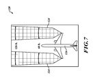
- FIG. 7 is a user interface image generated by the system shown in FIG. 2 ;
- FIGS. 8 and 9 are side and top views of an aircraft with a determined wing and nacelle exclusion zone.
- an aircraft 20 includes an exemplary airport surface collision-avoidance system (ASCAS) 18 .
- the ASCAS 18 includes horizontally and vertically discriminating radar sensors 26 included within aircraft light modules 30 or located at the other positions (e.g., vertical tail) about the aircraft 20 .
- the light modules 30 also include navigation/position lights 34 , a processor 36 , and a communication device 38 .
- the sensors 26 are in communication via the communication device 38 (wired or wirelessly) to a user interface (UI) device 44 .
- UI user interface
- the UI device 44 includes a processor 50 (optional), a communication device (wired or wireless) 52 , and alerting device(s) 54 .
- the UI device 44 provides audio and/or visual cues (e.g., via headphones, tablet PC, etc.) based on sensor-derived and processed information.
- the UI device 44 Based on information from the radar sensors 26 , the UI device 44 provides some or all of the following functions: detect and track intruder obstacles, evaluate and prioritize threats, radar control, and declare and determine actions. Once an alert associated with a detection has been produced, then execution of a collision-avoidance action (e.g., stop the aircraft, maneuver around obstacle, etc.) is manually performed by the operator or automatically by an automated system (e.g., autobrakes).
- a collision-avoidance action e.g., stop the aircraft, maneuver around obstacle, etc.
- an automated system e.g., autobrakes
- processing of the radar information is done by the processor 36 and/or the processor 50 at the UI device 44 .
- the antennas are installed at other fuselage areas, such as above each engine or at the nose of the aircraft, etc. Even though the antennas are not at the wingtip, the reflection data (radar return data) is buffered (stored), thus allowing the image 120 to be displayed.
- the information from multiple radar systems may be used to attain full coverage relative to the aircraft 20 , the wingtips, nacelles, and/or other aircraft structures.
- all radar reflection data is stored in a three-dimensional buffer referenced to the vehicle (e.g., aircraft).
- the pilot is alerted aurally, visually, and/or tactilely.
- a visual alert presented on an electronic flight bag (EFB) display shows aircraft wingtips outlined or a highlight of any obstructions.
- Aural alerting is through existing installed equipment, such as the interphone or other warning electronics or possibly the enhanced ground proximity warning system (EGPWS) platform.
- EFB electronic flight bag
- two antennas (or two antenna arrays) arranged vertically and spaced at a precise interval (e.g., ⁇ /2 (half wavelength)).
- a single radar pulse is emitted from the two antennas or a third antenna. Any radar pulse returns (reflections) are received by the vertically separated antennas.
- the return signals are sent to the processor ( 36 , 50 ) that determines vertical position of an obstacle (i.e., performs vertical discrimination) based on a determined phase differential between two corresponding received return signals.
- the processor ( 36 , 50 ) determines horizontal and vertical information for obstacles based on the horizontal and vertical discriminations performed on the raw radar return signals. If any identified obstacles are located both horizontally and vertically within a previously defined wingtip protection zone 66 that extends forward vertically and laterally from a wingtip of an aircraft 62 —see FIGS. 3 and 4 , the identified obstacle is treated as a possible threat. An alert for all threats is outputted to the operator of the aircraft 62 .
- the antennas can be implemented in many ways.
- a 4 ⁇ 2 array of antenna elements allows for a four input digital beam forming algorithm to discriminate targets in the horizontal direction and a two input monopulse discrimination of targets in the vertical direction.
- Monopulse discrimination is implemented as a phase comparison via a simple equation:
- ⁇ ⁇ ⁇ z R ⁇ ⁇ ⁇ ⁇ ⁇ 2 ⁇ ⁇ ⁇ ⁇ d
- the sign of the offset indicates whether the target is above or below the boresight.
- the processor ( 36 , 50 ) stores obstacle information in a three-dimensional buffer, where the wingtip protection zone 66 includes a subset of information (i.e., cells, voxels) from the three-dimensional buffer.
- the phase differential is used to determine if any of the detected obstacles are in the “exclusion zone” through which the wing will travel. Objects above or below this exclusion zone may be ignored.
- a runway sign 68 and service truck 70 are shown in front of the aircraft 62 . The runway sign 68 and service truck 70 are not considered a threat to the wing/wingtip of the aircraft 62 because the are below the wingtip protection zone 66 .
- FIG. 5 shows representative beam patterns of a notional sensor having a two channel input used for incoming signal phase detection.
- the use of a wide field of view sensor having the given wide pattern characteristics alone provides range capability only to a given target.
- the use of the dual channels, and through the use of phase comparison as described above, permits the simple sensor to perform angular location on the target and permits the determination of height, or in the case of proscenium signs or thresholds, the projection downward, and extent of the target.
- FIG. 6 shows how the dual channel (in each plane, but the elevation is shown here) receiver can determine the vertical placement of the target via phase comparison, and that the resulting phase differentials are easily measured to provide a height to accuracies that permit the establishment of the required “safe zone” for passage of the wing and/or the nacelles.
- FIG. 7 shows a top-down image 120 presented on a display that is part of the alerting device 54 .
- the image 120 includes an ownship aircraft icon 126 with two radar beam coverage areas 124 that project forward from wingtips of the icon 126 .
- the coverage areas 124 show only what is identified as being within the zone 66 .
- Two range rings 132 , 134 arbitrarily placed at maximum and half range are shown on the image 120 at fixed distances in front of the wing and can be scaled using either an interface on the EFB or IPAD, a tablet computer commercially available from Apple Inc. of Cupertino, Calif., or the cursor control device (CCD) in the aircraft, when shown on a navigation display.
- CCD cursor control device
- the expanded protection zone 84 includes a protection volume ahead of part of the aircraft's wings and engine nacelles.
- the zone 84 is thicker vertically along the projected path of the below wing engine nacelles.
- the zone 84 may be modified to provide a protection zone around any structure that extends above or below the wing.
- the runway sign 68 and the service truck 70 are considered a threat to the wing/wingtip of the aircraft 62 because their corresponding radar reflection signals appear within the expanded protection zone 84 .
Landscapes
- Engineering & Computer Science (AREA)
- Radar, Positioning & Navigation (AREA)
- Remote Sensing (AREA)
- Physics & Mathematics (AREA)
- General Physics & Mathematics (AREA)
- Aviation & Aerospace Engineering (AREA)
- Computer Networks & Wireless Communication (AREA)
- Electromagnetism (AREA)
- Mechanical Engineering (AREA)
- Human Computer Interaction (AREA)
- Traffic Control Systems (AREA)
- Radar Systems Or Details Thereof (AREA)
Abstract
Description
where
-
- λ is the wavelength of the radar frequency,
- d is the distance between the antenna elements,
- Δφ is the phase difference of the received signals of the two elements, in radians,
- R is the range to the target determined by the radar, and
- Δz is the vertical offset of the target from the antenna boresight.
Claims (15)
Priority Applications (4)
| Application Number | Priority Date | Filing Date | Title |
|---|---|---|---|
| US13/899,298 US9229101B2 (en) | 2012-05-30 | 2013-05-21 | Systems and methods for performing wingtip protection |
| EP13184623.0A EP2713181A1 (en) | 2012-09-27 | 2013-09-16 | Systems and methods for performing wingtip protection |
| JP2013193204A JP2014071111A (en) | 2012-09-27 | 2013-09-18 | Systems and methods for performing wingtip protection |
| CN201310590522.7A CN103700288A (en) | 2012-09-27 | 2013-09-26 | Systems and methods for performing wingtip protection |
Applications Claiming Priority (3)
| Application Number | Priority Date | Filing Date | Title |
|---|---|---|---|
| US201261653297P | 2012-05-30 | 2012-05-30 | |
| US201261706632P | 2012-09-27 | 2012-09-27 | |
| US13/899,298 US9229101B2 (en) | 2012-05-30 | 2013-05-21 | Systems and methods for performing wingtip protection |
Publications (2)
| Publication Number | Publication Date |
|---|---|
| US20130321194A1 US20130321194A1 (en) | 2013-12-05 |
| US9229101B2 true US9229101B2 (en) | 2016-01-05 |
Family
ID=49669535
Family Applications (4)
| Application Number | Title | Priority Date | Filing Date |
|---|---|---|---|
| US13/872,889 Active 2034-01-22 US9223017B2 (en) | 2012-05-30 | 2013-04-29 | Systems and methods for enhanced awareness of obstacle proximity during taxi operations |
| US13/888,216 Active 2036-11-01 US10274595B2 (en) | 2012-05-30 | 2013-05-06 | Systems and methods for performing vehicle collision-avoidance warning via sensor pulse |
| US13/889,537 Abandoned US20140085124A1 (en) | 2012-05-30 | 2013-05-08 | Systems and methods for using radar-adaptive beam pattern for wingtip protection |
| US13/899,298 Active 2034-03-01 US9229101B2 (en) | 2012-05-30 | 2013-05-21 | Systems and methods for performing wingtip protection |
Family Applications Before (3)
| Application Number | Title | Priority Date | Filing Date |
|---|---|---|---|
| US13/872,889 Active 2034-01-22 US9223017B2 (en) | 2012-05-30 | 2013-04-29 | Systems and methods for enhanced awareness of obstacle proximity during taxi operations |
| US13/888,216 Active 2036-11-01 US10274595B2 (en) | 2012-05-30 | 2013-05-06 | Systems and methods for performing vehicle collision-avoidance warning via sensor pulse |
| US13/889,537 Abandoned US20140085124A1 (en) | 2012-05-30 | 2013-05-08 | Systems and methods for using radar-adaptive beam pattern for wingtip protection |
Country Status (6)
| Country | Link |
|---|---|
| US (4) | US9223017B2 (en) |
| EP (2) | EP3832348B1 (en) |
| JP (1) | JP2015524111A (en) |
| CN (1) | CN104380363A (en) |
| IN (1) | IN2014DN09499A (en) |
| WO (1) | WO2013181351A1 (en) |
Cited By (3)
| Publication number | Priority date | Publication date | Assignee | Title |
|---|---|---|---|---|
| US10830873B2 (en) | 2017-01-06 | 2020-11-10 | Honeywell International Inc. | Synthesizer for radar sensing |
| US11480429B2 (en) * | 2018-12-19 | 2022-10-25 | Airbus Helicopters | Method of detecting proximity to the ground of a side arrangement on an aircraft, and an aircraft |
| US12345798B2 (en) | 2022-02-04 | 2025-07-01 | Honeywell International Inc. | FMCW radar with elevation scanning |
Families Citing this family (28)
| Publication number | Priority date | Publication date | Assignee | Title |
|---|---|---|---|---|
| US9223017B2 (en) | 2012-05-30 | 2015-12-29 | Honeywell International Inc. | Systems and methods for enhanced awareness of obstacle proximity during taxi operations |
| EP2901178A4 (en) | 2012-09-27 | 2016-03-30 | Honeywell Int Inc | SYSTEMS AND METHODS FOR USING ADAPTIVE RADAR BEAM CONFIGURATION FOR WINGBORNE PROTECTION |
| US9286794B2 (en) | 2013-10-18 | 2016-03-15 | Elwha Llc | Pedestrian warning system |
| US20150029051A1 (en) * | 2013-07-25 | 2015-01-29 | Elwha Llc | Wearable radar reflectors |
| US10431105B2 (en) | 2014-01-07 | 2019-10-01 | Honeywell International Inc. | Enhanced awareness of obstacle proximity |
| US10963133B2 (en) | 2014-01-07 | 2021-03-30 | Honeywell International Inc. | Enhanced awareness of obstacle proximity |
| US20150213721A1 (en) * | 2014-01-30 | 2015-07-30 | Honeywell International Inc. | Passive aircraft wingtip strike detection system and method |
| RU2553270C1 (en) * | 2014-04-15 | 2015-06-10 | Федеральное государственное казенное военное образовательное учреждение высшего профессионального образования "ВОЕННАЯ АКАДЕМИЯ СВЯЗИ имени Маршала Советского Союза С.М. Буденного" Министерства обороны Российской Федерации | Method and apparatus for determining angular orientation of aircraft |
| FR3020043B1 (en) * | 2014-04-17 | 2016-04-22 | Sagem Defense Securite | AIRCRAFT COMPRISING A RETRACTABLE ARM HAVING OBSTACLE DETECTOR |
| US9721475B2 (en) | 2014-09-05 | 2017-08-01 | Honeywell International Inc. | Systems and methods for displaying object and/or approaching vehicle data within an airport moving map |
| WO2016045703A1 (en) * | 2014-09-23 | 2016-03-31 | Airbus Operations (S.A.S.) | Method and device for determining the ground collision risk of an aircraft |
| CN107004369A (en) | 2014-11-05 | 2017-08-01 | 霍尼韦尔国际公司 | Use the Air Traffic System of program trajectory predictions |
| US9536435B1 (en) | 2015-07-13 | 2017-01-03 | Double Black Aviation Technology L.L.C. | System and method for optimizing an aircraft trajectory |
| USD842718S1 (en) | 2017-07-25 | 2019-03-12 | uAvionix Corporation | Position indicator |
| US10156627B2 (en) | 2015-10-15 | 2018-12-18 | uAvionix Corporation | Aircraft navigation light ADS-B radio |
| US9898934B2 (en) | 2016-07-25 | 2018-02-20 | Honeywell International Inc. | Prediction of vehicle maneuvers |
| US9997078B2 (en) | 2016-09-09 | 2018-06-12 | Garmin International, Inc. | Obstacle determination and display system |
| CN108154715B (en) * | 2016-12-02 | 2022-02-25 | 上海航空电器有限公司 | Lateral collision monitoring method |
| US10403158B2 (en) * | 2017-04-06 | 2019-09-03 | The Boeing Company | Vertical landing vehicle, situational awareness system, and method thereof |
| US10453351B2 (en) * | 2017-07-17 | 2019-10-22 | Aurora Flight Sciences Corporation | System and method for detecting obstacles in aerial systems |
| US10410530B1 (en) | 2018-02-27 | 2019-09-10 | Honeywell International Inc. | Systems and methods for detecting potential surface collisions and providing warnings onboard an aircraft or airport vehicle |
| US10234303B1 (en) | 2018-02-28 | 2019-03-19 | Honeywell International Inc. | Methods and systems for providing visually automated in-cockpit aircraft docking guidance with use of airport moving map applications |
| CN112088344B (en) * | 2018-12-04 | 2024-02-02 | 深圳市大疆创新科技有限公司 | Method and system for controlling movement of movable devices |
| US10867522B1 (en) * | 2019-08-28 | 2020-12-15 | Honeywell International Inc. | Systems and methods for vehicle pushback collision notification and avoidance |
| CN114423673B (en) * | 2019-09-30 | 2023-04-04 | 本田技研工业株式会社 | Straddle-type vehicle, control method for straddle-type vehicle, and storage medium |
| DE102020103298B4 (en) | 2020-02-10 | 2023-12-14 | Evitado Technologies GmbH | Method and system for monitoring an object in the vicinity of an aircraft |
| US11770689B2 (en) * | 2020-12-16 | 2023-09-26 | Qorvo Us, Inc. | Systems and methods for communication via passive radar modulation |
| CN114044164B (en) * | 2021-11-10 | 2023-06-27 | 北京环境特性研究所 | Low-scattering carrier for RCS (wing component handling System) test of wing component |
Citations (36)
| Publication number | Priority date | Publication date | Assignee | Title |
|---|---|---|---|---|
| US3212089A (en) * | 1963-09-30 | 1965-10-12 | Longacre Andrew | Monopulse resolution improvement |
| US3349394A (en) * | 1965-12-23 | 1967-10-24 | Motorola Inc | Radar sensing system |
| US3761927A (en) * | 1972-03-20 | 1973-09-25 | United Aircraft Corp | Rf phase detected interferometer radar |
| US3766556A (en) * | 1972-03-28 | 1973-10-16 | United Aircraft Corp | Channel switching phase interferometer radar receiver |
| US4101893A (en) * | 1977-08-05 | 1978-07-18 | The United States Of America As Represented By The Secretary Of The Navy | Aircraft landing aid for zero-zero visibility landings |
| US4160974A (en) * | 1976-10-29 | 1979-07-10 | The Singer Company | Target sensing and homing system |
| US4170774A (en) * | 1972-01-24 | 1979-10-09 | United Technologies Corporation | Amplitude selected phase interferometer angle measuring radar |
| US4334224A (en) * | 1979-08-23 | 1982-06-08 | The Marconi Company Limited | Secondary surveillance radar |
| US4918442A (en) * | 1988-10-03 | 1990-04-17 | Bogart Jr Donald W | Airplane collision avoidance system |
| EP0526424A2 (en) | 1991-07-31 | 1993-02-03 | CARELLO S.p.A. | A light unit for vehicles, incorporating an obstacle-detection system |
| US6087995A (en) * | 1999-02-17 | 2000-07-11 | Anritsu Company | Universal autoradar antenna alignment system |
| US6118401A (en) | 1996-07-01 | 2000-09-12 | Sun Microsystems, Inc. | Aircraft ground collision avoidance system and method |
| US6297762B1 (en) * | 1979-06-27 | 2001-10-02 | Raytheon Company | Electronic countermeasures system |
| US6486798B2 (en) | 2000-05-11 | 2002-11-26 | Rastar Corporation | System and method of preventing aircraft wing damage |
| US6963293B1 (en) | 2000-05-11 | 2005-11-08 | Rastar Corporation | System and method of preventing aircraft wingtip ground incursion |
| US20060022866A1 (en) | 2002-01-17 | 2006-02-02 | The Ohio State University | Vehicle obstacle warning radar |
| US20060044177A1 (en) | 2004-09-01 | 2006-03-02 | The Boeing Company | Radar system and method for determining the height of an object |
| US7055994B2 (en) | 2000-09-19 | 2006-06-06 | L-3 Communications Corporation | Light source assembly and methods for aircraft external lighting |
| US7188983B2 (en) | 2004-01-05 | 2007-03-13 | Matthew Dunn | Vehicle lighting apparatus and method |
| EP1923717A1 (en) | 2006-11-15 | 2008-05-21 | M/A-Com, Inc. | Method and apparatus for discriminating with respect to low elevation target objections |
| US7379165B2 (en) | 2004-09-30 | 2008-05-27 | The Boeing Company | Ground vehicle collision prevention systems and methods |
| EP1787142B1 (en) | 2004-09-07 | 2008-11-19 | William Michael Butler | A collision avoidance warning and taxiing guidance device |
| US20090174591A1 (en) | 2007-03-16 | 2009-07-09 | Thales | Obstacle detection system notably for an anticollision system |
| US20100204867A1 (en) | 2007-05-04 | 2010-08-12 | Teledyne Australia Pty Ltd | Collision avoidance system and method |
| US7783427B1 (en) | 2006-07-14 | 2010-08-24 | Rockwell Collins, Inc. | Combined runway obstacle detection system and method |
| US20110087417A1 (en) | 2004-09-30 | 2011-04-14 | The Boeing Company | Ground Vehicle Collision Prevention Systems and Methods |
| US20110279304A1 (en) | 2010-05-11 | 2011-11-17 | Electronic Navigation Research Institute, Independent Administrative Institution | Millimeter wave radar-equipped headlamp |
| US8121786B2 (en) | 2007-12-20 | 2012-02-21 | Airbus Operations Sas | Method and device for preventing collisions on the ground for aircraft |
| US8264377B2 (en) | 2009-03-02 | 2012-09-11 | Griffith Gregory M | Aircraft collision avoidance system |
| US20130321169A1 (en) | 2012-05-30 | 2013-12-05 | Honeywell International Inc. | Airport surface collision-avoidance system (ascas) |
| US20130325312A1 (en) | 2012-05-30 | 2013-12-05 | Honeywell International Inc. | Systems and methods for enhanced awareness of obstacle proximity during taxi operations |
| US20130321192A1 (en) | 2012-05-30 | 2013-12-05 | Honeywell International Inc. | Collision-avoidance system for ground crew using sensors |
| US20130321176A1 (en) | 2012-05-30 | 2013-12-05 | Honeywell International Inc. | Systems and methods for displaying obstacle-avoidance information during surface operations |
| US20130321193A1 (en) | 2012-05-30 | 2013-12-05 | Honeywell International Inc. | Systems and methods for filtering wingtip sensor information |
| US20130325245A1 (en) | 2012-05-30 | 2013-12-05 | Honeywell International Inc. | Systems and methods for displaying aircraft braking distance during surface operations |
| US8988277B2 (en) * | 2011-11-08 | 2015-03-24 | Raytheon Company | Dual monopulse/interferometer radar AESA aperture |
Family Cites Families (58)
| Publication number | Priority date | Publication date | Assignee | Title |
|---|---|---|---|---|
| CH434030A (en) * | 1963-07-02 | 1967-04-15 | Bofors Ab | Fire control system for a ship |
| US3372890A (en) * | 1966-02-04 | 1968-03-12 | Martin Marietta Corp | Data processor for circular scanning tracking system |
| US3416752A (en) * | 1966-03-23 | 1968-12-17 | Martin Marietta Corp | Correlation guidance system having multiple switchable field of view |
| US4128837A (en) * | 1968-07-22 | 1978-12-05 | Rockwell International Corporation | Prediction computation for weapon control |
| US3841585A (en) * | 1973-03-06 | 1974-10-15 | Us Army | Constant bearing course homing missile |
| DE2623643C2 (en) * | 1976-05-26 | 1986-11-20 | Daimler-Benz Ag, 7000 Stuttgart | Method for automatically regulating the safety distance between a vehicle and vehicles in front and a device for carrying out this method |
| US4148029A (en) * | 1976-10-13 | 1979-04-03 | Westinghouse Electric Corp. | System for estimating acceleration of maneuvering targets |
| FR2378318A1 (en) * | 1977-01-21 | 1978-08-18 | Thomson Csf | MOBILE TARGET TRACKING SYSTEM |
| US5129595A (en) * | 1991-07-03 | 1992-07-14 | Alliant Techsystems Inc. | Focal plane array seeker for projectiles |
| JPH07306995A (en) | 1994-05-13 | 1995-11-21 | Hitachi Ltd | Traffic safety system, pedestrian portable device and vehicle-mounted device used for the system, and pedestrian danger warning method |
| KR100270523B1 (en) * | 1995-12-27 | 2000-11-01 | 정몽규 | Unmanned car having control function according to the road condition |
| JP3421058B2 (en) | 1997-12-22 | 2003-06-30 | 三菱電機株式会社 | Automotive radar equipment |
| JP2000019246A (en) | 1998-07-03 | 2000-01-21 | Denso Corp | Obstacle detection system, radar device, transponder |
| GB2342251A (en) * | 1998-09-29 | 2000-04-05 | Secr Defence | Proximity measuring apparatus |
| US6459411B2 (en) | 1998-12-30 | 2002-10-01 | L-3 Communications Corporation | Close/intra-formation positioning collision avoidance system and method |
| JP2001021644A (en) | 1999-07-12 | 2001-01-26 | Denso Corp | Obstacle detection system, in-vehicle radar device, wireless portable device |
| WO2003009254A1 (en) | 2001-07-16 | 2003-01-30 | 727823 Ontario Limited | Method and apparatus for avoiding collisions |
| FR2837591B1 (en) * | 2002-03-20 | 2004-07-02 | Airbus France | AIRPORT VISUALIZATION DEVICE |
| JP2004258898A (en) | 2003-02-25 | 2004-09-16 | Denso Corp | Vehicle-mounted device that detects the position of a pedestrian or vehicle |
| US7095336B2 (en) * | 2003-09-23 | 2006-08-22 | Optimus Corporation | System and method for providing pedestrian alerts |
| US20050107934A1 (en) | 2003-11-18 | 2005-05-19 | Caterpillar Inc. | Work site tracking system and method |
| IL161082A (en) * | 2004-03-25 | 2008-08-07 | Rafael Advanced Defense Sys | System and method for automatically acquiring a target with a narrow field-of-view gimbaled imaging sensor |
| US7541944B2 (en) * | 2004-07-12 | 2009-06-02 | The Boeing Company | Systems and methods for collision avoidance |
| US7379014B1 (en) * | 2004-09-15 | 2008-05-27 | Rockwell Collins, Inc. | Taxi obstacle detecting radar |
| FR2888955B1 (en) | 2005-07-21 | 2007-08-24 | Airbus Sas | METHOD AND DEVICE FOR SECURING AUTOMATIC LOW ALTITUDE FLIGHT OF AN AIRCRAFT |
| JP4812080B2 (en) * | 2005-10-12 | 2011-11-09 | 株式会社 日立ディスプレイズ | Image display device |
| JP2007132768A (en) | 2005-11-10 | 2007-05-31 | Hitachi Ltd | In-vehicle radar device with communication function |
| CN1979517A (en) | 2005-11-30 | 2007-06-13 | 华为技术有限公司 | Radio-frequency identifying method and apparatus |
| CN100405775C (en) | 2006-01-16 | 2008-07-23 | 北京大学 | Anti-collision reading method of radio frequency identification information |
| DE102006007536A1 (en) | 2006-02-16 | 2007-08-30 | Aloys Wobben | Wind turbine with flight lighting device |
| US7592929B2 (en) * | 2006-04-06 | 2009-09-22 | Honeywell International Inc. | Runway and taxiway turning guidance |
| JP4739112B2 (en) | 2006-05-17 | 2011-08-03 | 住友ナコ マテリアル ハンドリング株式会社 | Industrial vehicle safety device |
| CA2549870A1 (en) | 2006-06-06 | 2007-12-06 | Donald Wayne Ablitt | Collision avoidance and rfid system |
| FR2908218B1 (en) * | 2006-11-07 | 2014-08-15 | Thales Sa | DEVICE FOR AIDING NAVIGATION OF AN AIRCRAFT IN AN AIRPORT AREA |
| CN100466014C (en) | 2006-11-08 | 2009-03-04 | 北京航空航天大学 | Surveillance System for Moving Targets on Airport Surface |
| JP2008123014A (en) | 2006-11-08 | 2008-05-29 | Shinko Electric Co Ltd | Contact prevention system |
| US7865300B2 (en) * | 2006-11-15 | 2011-01-04 | International Business Machines Corporation | System and method for providing turn-by-turn directions to a moving waypoint |
| FR2910681B1 (en) * | 2006-12-20 | 2009-03-06 | Thales Sa | SELECTIVE DISPLAY SYSTEM FOR AIRCRAFT TRAFFIC INFORMATION |
| JP4920431B2 (en) | 2007-01-23 | 2012-04-18 | 本田技研工業株式会社 | Collision damage reduction system |
| FR2917222B1 (en) * | 2007-06-05 | 2009-10-30 | Thales Sa | COLLISION PREVENTION DEVICE AND METHOD FOR A GROUND VEHICLE |
| FR2917223B1 (en) * | 2007-06-08 | 2009-07-17 | Thales Sa | AIDING SYSTEM FOR GUIDING AN AIRCRAFT ON AN AIRPORT |
| CN101122957B (en) | 2007-09-06 | 2010-11-17 | 复旦大学 | An RFID reader-writer with collision detection function and its collision detection method |
| US8786467B2 (en) | 2007-11-14 | 2014-07-22 | The Boeing Company | Methods and systems for filtering traffic information for display |
| US8077081B2 (en) * | 2008-01-29 | 2011-12-13 | Honeywell International Inc. | Ground collision instrument for aircraft and marine vehicles |
| FR2932279B1 (en) * | 2008-06-10 | 2011-08-19 | Thales Sa | DEVICE AND METHOD FOR MONITORING OBSTRUCTIONS IN THE ENVIRONMENT CLOSE TO AN AIRCRAFT. |
| US7932838B2 (en) * | 2008-11-17 | 2011-04-26 | Honeywell International, Inc. | Aircraft collision avoidance system |
| FR2947639B1 (en) * | 2009-07-03 | 2012-01-13 | Airbus Operations Sas | METHOD AND DEVICE FOR DETECTING CIRCULATING AIRCRAFT IN AN AIRSPACE SURROUNDING AN AIRCRAFT |
| CN101593437A (en) | 2009-07-10 | 2009-12-02 | 贵州盖克无人机有限责任公司 | A kind of unmanned plane flight collision avoidance method and device |
| JP2011028579A (en) | 2009-07-27 | 2011-02-10 | Toshiba Corp | Ground travel guidance support system |
| CN101989383A (en) | 2009-08-03 | 2011-03-23 | 西安费斯达自动化工程有限公司 | Miniature TCAS (Traffic Collision Avoidance System) |
| FR2950149B1 (en) * | 2009-09-17 | 2012-08-17 | Mbda France | METHOD AND SYSTEM FOR AVOIDING AN INTERCEPTION MACHINE BY AN AIR MOBILE |
| US20110125349A1 (en) * | 2009-11-23 | 2011-05-26 | Danny Ace | Integrated Bird-Aircraft Strike Prevention System - IBSPS |
| US8366054B2 (en) * | 2009-12-17 | 2013-02-05 | The United States Of America As Represented By The Secretary Of The Navy | Hand launchable unmanned aerial vehicle |
| US8922431B2 (en) * | 2010-04-13 | 2014-12-30 | Becker Research And Development (Proprietary) Limited | Apparatus, a system and a method for collission avoidance |
| DE102010022282A1 (en) * | 2010-05-31 | 2011-12-01 | Andreas Lewandowski | Method and radio system for warning of moving persons and objects in traffic |
| US8325082B2 (en) * | 2010-08-31 | 2012-12-04 | Raytheon Company | Predictive and adaptive wide area surveillance |
| US8378881B2 (en) * | 2010-10-18 | 2013-02-19 | Raytheon Company | Systems and methods for collision avoidance in unmanned aerial vehicles |
| CN202193050U (en) | 2011-08-17 | 2012-04-18 | 胡鹏 | Novel anti-collision system |
-
2013
- 2013-04-29 US US13/872,889 patent/US9223017B2/en active Active
- 2013-05-06 US US13/888,216 patent/US10274595B2/en active Active
- 2013-05-08 US US13/889,537 patent/US20140085124A1/en not_active Abandoned
- 2013-05-21 US US13/899,298 patent/US9229101B2/en active Active
- 2013-05-30 IN IN9499DEN2014 patent/IN2014DN09499A/en unknown
- 2013-05-30 EP EP21150078.0A patent/EP3832348B1/en active Active
- 2013-05-30 JP JP2015515177A patent/JP2015524111A/en active Pending
- 2013-05-30 CN CN201380027882.4A patent/CN104380363A/en active Pending
- 2013-05-30 WO PCT/US2013/043287 patent/WO2013181351A1/en not_active Ceased
- 2013-05-30 EP EP13796644.6A patent/EP2856455B1/en active Active
Patent Citations (40)
| Publication number | Priority date | Publication date | Assignee | Title |
|---|---|---|---|---|
| US3212089A (en) * | 1963-09-30 | 1965-10-12 | Longacre Andrew | Monopulse resolution improvement |
| US3349394A (en) * | 1965-12-23 | 1967-10-24 | Motorola Inc | Radar sensing system |
| US4170774A (en) * | 1972-01-24 | 1979-10-09 | United Technologies Corporation | Amplitude selected phase interferometer angle measuring radar |
| US3761927A (en) * | 1972-03-20 | 1973-09-25 | United Aircraft Corp | Rf phase detected interferometer radar |
| US3766556A (en) * | 1972-03-28 | 1973-10-16 | United Aircraft Corp | Channel switching phase interferometer radar receiver |
| US4160974A (en) * | 1976-10-29 | 1979-07-10 | The Singer Company | Target sensing and homing system |
| US4101893A (en) * | 1977-08-05 | 1978-07-18 | The United States Of America As Represented By The Secretary Of The Navy | Aircraft landing aid for zero-zero visibility landings |
| US6297762B1 (en) * | 1979-06-27 | 2001-10-02 | Raytheon Company | Electronic countermeasures system |
| US4334224A (en) * | 1979-08-23 | 1982-06-08 | The Marconi Company Limited | Secondary surveillance radar |
| US4918442A (en) * | 1988-10-03 | 1990-04-17 | Bogart Jr Donald W | Airplane collision avoidance system |
| EP0526424A2 (en) | 1991-07-31 | 1993-02-03 | CARELLO S.p.A. | A light unit for vehicles, incorporating an obstacle-detection system |
| US6118401A (en) | 1996-07-01 | 2000-09-12 | Sun Microsystems, Inc. | Aircraft ground collision avoidance system and method |
| US6087995A (en) * | 1999-02-17 | 2000-07-11 | Anritsu Company | Universal autoradar antenna alignment system |
| US6486798B2 (en) | 2000-05-11 | 2002-11-26 | Rastar Corporation | System and method of preventing aircraft wing damage |
| US6963293B1 (en) | 2000-05-11 | 2005-11-08 | Rastar Corporation | System and method of preventing aircraft wingtip ground incursion |
| US7055994B2 (en) | 2000-09-19 | 2006-06-06 | L-3 Communications Corporation | Light source assembly and methods for aircraft external lighting |
| US20060022866A1 (en) | 2002-01-17 | 2006-02-02 | The Ohio State University | Vehicle obstacle warning radar |
| US7188983B2 (en) | 2004-01-05 | 2007-03-13 | Matthew Dunn | Vehicle lighting apparatus and method |
| US20060044177A1 (en) | 2004-09-01 | 2006-03-02 | The Boeing Company | Radar system and method for determining the height of an object |
| EP1787142B1 (en) | 2004-09-07 | 2008-11-19 | William Michael Butler | A collision avoidance warning and taxiing guidance device |
| US7379165B2 (en) | 2004-09-30 | 2008-05-27 | The Boeing Company | Ground vehicle collision prevention systems and methods |
| US7579980B2 (en) | 2004-09-30 | 2009-08-25 | The Boeing Company | Radar based ground vehicle collision prevention |
| US7869305B2 (en) | 2004-09-30 | 2011-01-11 | The Boeing Company | Ground vehicle collision prevention systems and methods |
| US20110087417A1 (en) | 2004-09-30 | 2011-04-14 | The Boeing Company | Ground Vehicle Collision Prevention Systems and Methods |
| US7783427B1 (en) | 2006-07-14 | 2010-08-24 | Rockwell Collins, Inc. | Combined runway obstacle detection system and method |
| EP1923717A1 (en) | 2006-11-15 | 2008-05-21 | M/A-Com, Inc. | Method and apparatus for discriminating with respect to low elevation target objections |
| US20090174591A1 (en) | 2007-03-16 | 2009-07-09 | Thales | Obstacle detection system notably for an anticollision system |
| US7903023B2 (en) | 2007-03-16 | 2011-03-08 | Thales | Obstacle detection system notably for an anticollision system |
| US20100204867A1 (en) | 2007-05-04 | 2010-08-12 | Teledyne Australia Pty Ltd | Collision avoidance system and method |
| US8121786B2 (en) | 2007-12-20 | 2012-02-21 | Airbus Operations Sas | Method and device for preventing collisions on the ground for aircraft |
| US8264377B2 (en) | 2009-03-02 | 2012-09-11 | Griffith Gregory M | Aircraft collision avoidance system |
| US20110279304A1 (en) | 2010-05-11 | 2011-11-17 | Electronic Navigation Research Institute, Independent Administrative Institution | Millimeter wave radar-equipped headlamp |
| US8988277B2 (en) * | 2011-11-08 | 2015-03-24 | Raytheon Company | Dual monopulse/interferometer radar AESA aperture |
| US20130321169A1 (en) | 2012-05-30 | 2013-12-05 | Honeywell International Inc. | Airport surface collision-avoidance system (ascas) |
| US20130325312A1 (en) | 2012-05-30 | 2013-12-05 | Honeywell International Inc. | Systems and methods for enhanced awareness of obstacle proximity during taxi operations |
| US20130321192A1 (en) | 2012-05-30 | 2013-12-05 | Honeywell International Inc. | Collision-avoidance system for ground crew using sensors |
| US20130321177A1 (en) | 2012-05-30 | 2013-12-05 | Honeywell International Inc. | Systems and methods for performing vehicle collision-avoidance warning via sensor pulse |
| US20130321176A1 (en) | 2012-05-30 | 2013-12-05 | Honeywell International Inc. | Systems and methods for displaying obstacle-avoidance information during surface operations |
| US20130321193A1 (en) | 2012-05-30 | 2013-12-05 | Honeywell International Inc. | Systems and methods for filtering wingtip sensor information |
| US20130325245A1 (en) | 2012-05-30 | 2013-12-05 | Honeywell International Inc. | Systems and methods for displaying aircraft braking distance during surface operations |
Non-Patent Citations (10)
| Title |
|---|
| Examination Report from counterpart European Patent Application No. 13184623.0, dated Jan. 31, 2014, 5 pp. |
| Jones, "Keeping Cars from Crashing," IEEE Spectrum, Sep. 3, 2001, 6 pp. |
| Langer et al. "Fusing Radar and Vision for Detecting, Classifying and Avoiding Roadway Obstacles," Intelligent Vehicles, Tokyo, Japan, Sep. 18-20, 1996, 6 pp. |
| Response to Examination Report dated Jan. 31, 2014, from counterpart European Patent Application No. 13184623.0, dated Dec. 18, 2014, 11 pp. |
| Search Report from counterpart European application No. 13184623.0, dated Jan. 22, 2014, 3 pp. |
| Shirakawa et al. "3D-Scan Millimeter-Wave Radar for Automotive Application," Fujitsu Ten Technical Journal No. 28, Feb. 2013, 5 pp. |
| U.S. Appl. No. 13/706,858, by Tomas Kabrt et al., filed Dec. 6, 2012. |
| U.S. Appl. No. 13/742,688 by James C. Kirk et al., filed Jan. 16, 2013. |
| U.S. Appl. No. 13/835,122 by Andrew F. Lamkin et al., filed Mar. 15, 2013. |
| U.S. Appl. No. 13/889,537 by Matej Dusik et al., filed May 8, 2013. |
Cited By (4)
| Publication number | Priority date | Publication date | Assignee | Title |
|---|---|---|---|---|
| US10830873B2 (en) | 2017-01-06 | 2020-11-10 | Honeywell International Inc. | Synthesizer for radar sensing |
| US11181616B2 (en) | 2017-01-06 | 2021-11-23 | Honeywell International Inc. | Synihesizer for radar sensing |
| US11480429B2 (en) * | 2018-12-19 | 2022-10-25 | Airbus Helicopters | Method of detecting proximity to the ground of a side arrangement on an aircraft, and an aircraft |
| US12345798B2 (en) | 2022-02-04 | 2025-07-01 | Honeywell International Inc. | FMCW radar with elevation scanning |
Also Published As
| Publication number | Publication date |
|---|---|
| EP3832348A1 (en) | 2021-06-09 |
| EP2856455A1 (en) | 2015-04-08 |
| EP2856455B1 (en) | 2021-01-27 |
| US9223017B2 (en) | 2015-12-29 |
| WO2013181351A1 (en) | 2013-12-05 |
| CN104380363A (en) | 2015-02-25 |
| IN2014DN09499A (en) | 2015-07-17 |
| US10274595B2 (en) | 2019-04-30 |
| EP3832348B1 (en) | 2025-01-15 |
| JP2015524111A (en) | 2015-08-20 |
| US20130321177A1 (en) | 2013-12-05 |
| US20130325312A1 (en) | 2013-12-05 |
| EP2856455A4 (en) | 2015-12-02 |
| US20140085124A1 (en) | 2014-03-27 |
| US20130321194A1 (en) | 2013-12-05 |
Similar Documents
| Publication | Publication Date | Title |
|---|---|---|
| US9229101B2 (en) | Systems and methods for performing wingtip protection | |
| EP2713181A1 (en) | Systems and methods for performing wingtip protection | |
| US9959774B2 (en) | Systems and methods for displaying obstacle-avoidance information during surface operations | |
| US10388173B2 (en) | Collision avoidance system for aircraft ground operations | |
| US7864096B2 (en) | Systems and methods for multi-sensor collision avoidance | |
| EP2669704B1 (en) | Airport surface collision-avoidance system (ASCAS) | |
| US20160282131A1 (en) | X-band avian radar detection and warning system | |
| US9472109B2 (en) | Obstacle detection system providing context awareness | |
| US10963133B2 (en) | Enhanced awareness of obstacle proximity | |
| US7783427B1 (en) | Combined runway obstacle detection system and method | |
| US9575174B2 (en) | Systems and methods for filtering wingtip sensor information | |
| US10431105B2 (en) | Enhanced awareness of obstacle proximity | |
| US11164460B2 (en) | System for collision avoidance and method for collision avoidance | |
| US10281563B2 (en) | Method and device for determining a detection range of a traffic route | |
| KR102183700B1 (en) | Method for incorporating foreign object location information provided by fixed detection devices | |
| Martinez et al. | Detect and avoid considerations for safe suas operations in urban environments | |
| Thupakula | A methodology for collision prediction and alert generation in airport environment | |
| Stamm | Recent UAS Work in the NAS |
Legal Events
| Date | Code | Title | Description |
|---|---|---|---|
| AS | Assignment |
Owner name: HONEYWELL INTERNATIONAL INC., NEW JERSEY Free format text: ASSIGNMENT OF ASSIGNORS INTEREST;ASSIGNORS:KIRK, JAMES C;BUI, LONG;VACANTI, DAVID C;AND OTHERS;SIGNING DATES FROM 20130503 TO 20130520;REEL/FRAME:030460/0721 |
|
| STCF | Information on status: patent grant |
Free format text: PATENTED CASE |
|
| MAFP | Maintenance fee payment |
Free format text: PAYMENT OF MAINTENANCE FEE, 4TH YEAR, LARGE ENTITY (ORIGINAL EVENT CODE: M1551); ENTITY STATUS OF PATENT OWNER: LARGE ENTITY Year of fee payment: 4 |
|
| MAFP | Maintenance fee payment |
Free format text: PAYMENT OF MAINTENANCE FEE, 8TH YEAR, LARGE ENTITY (ORIGINAL EVENT CODE: M1552); ENTITY STATUS OF PATENT OWNER: LARGE ENTITY Year of fee payment: 8 |