US9227740B2 - Device for monitoring the attitude of a satellite, and method for controlling a satellite provided with said device - Google Patents
Device for monitoring the attitude of a satellite, and method for controlling a satellite provided with said device Download PDFInfo
- Publication number
- US9227740B2 US9227740B2 US13/980,667 US201213980667A US9227740B2 US 9227740 B2 US9227740 B2 US 9227740B2 US 201213980667 A US201213980667 A US 201213980667A US 9227740 B2 US9227740 B2 US 9227740B2
- Authority
- US
- United States
- Prior art keywords
- optical properties
- commanded
- solar
- whose optical
- flaps
- Prior art date
- Legal status (The legal status is an assumption and is not a legal conclusion. Google has not performed a legal analysis and makes no representation as to the accuracy of the status listed.)
- Active, expires
Links
- 238000000034 method Methods 0.000 title claims description 10
- 238000012544 monitoring process Methods 0.000 title 1
- 230000003287 optical effect Effects 0.000 claims abstract description 128
- 230000003068 static effect Effects 0.000 claims description 21
- 239000000463 material Substances 0.000 claims description 15
- 230000004048 modification Effects 0.000 claims description 2
- 238000012986 modification Methods 0.000 claims description 2
- 210000004027 cell Anatomy 0.000 description 14
- 230000002745 absorbent Effects 0.000 description 12
- 239000002250 absorbent Substances 0.000 description 12
- 239000008186 active pharmaceutical agent Substances 0.000 description 12
- 230000007704 transition Effects 0.000 description 7
- 238000002310 reflectometry Methods 0.000 description 6
- 238000006243 chemical reaction Methods 0.000 description 5
- 230000000694 effects Effects 0.000 description 4
- 230000006870 function Effects 0.000 description 2
- 238000004519 manufacturing process Methods 0.000 description 2
- 230000007246 mechanism Effects 0.000 description 2
- 239000003380 propellant Substances 0.000 description 2
- 210000004460 N cell Anatomy 0.000 description 1
- 239000004642 Polyimide Substances 0.000 description 1
- 238000010521 absorption reaction Methods 0.000 description 1
- XAGFODPZIPBFFR-UHFFFAOYSA-N aluminium Chemical compound [Al] XAGFODPZIPBFFR-UHFFFAOYSA-N 0.000 description 1
- 229910052782 aluminium Inorganic materials 0.000 description 1
- 230000005540 biological transmission Effects 0.000 description 1
- 230000008859 change Effects 0.000 description 1
- 238000004590 computer program Methods 0.000 description 1
- 238000010586 diagram Methods 0.000 description 1
- 230000005611 electricity Effects 0.000 description 1
- 238000005516 engineering process Methods 0.000 description 1
- 239000004973 liquid crystal related substance Substances 0.000 description 1
- 239000011159 matrix material Substances 0.000 description 1
- 229920001721 polyimide Polymers 0.000 description 1
- 230000005855 radiation Effects 0.000 description 1
- 229920006395 saturated elastomer Polymers 0.000 description 1
- 239000000126 substance Substances 0.000 description 1
Images


Classifications
-
- B—PERFORMING OPERATIONS; TRANSPORTING
- B64—AIRCRAFT; AVIATION; COSMONAUTICS
- B64G—COSMONAUTICS; VEHICLES OR EQUIPMENT THEREFOR
- B64G1/00—Cosmonautic vehicles
- B64G1/22—Parts of, or equipment specially adapted for fitting in or to, cosmonautic vehicles
- B64G1/24—Guiding or controlling apparatus, e.g. for attitude control
- B64G1/244—Spacecraft control systems
-
- B—PERFORMING OPERATIONS; TRANSPORTING
- B64—AIRCRAFT; AVIATION; COSMONAUTICS
- B64G—COSMONAUTICS; VEHICLES OR EQUIPMENT THEREFOR
- B64G1/00—Cosmonautic vehicles
- B64G1/22—Parts of, or equipment specially adapted for fitting in or to, cosmonautic vehicles
- B64G1/24—Guiding or controlling apparatus, e.g. for attitude control
- B64G1/36—Guiding or controlling apparatus, e.g. for attitude control using sensors, e.g. sun-sensors, horizon sensors
- B64G1/363—Guiding or controlling apparatus, e.g. for attitude control using sensors, e.g. sun-sensors, horizon sensors using sun sensors
-
- B—PERFORMING OPERATIONS; TRANSPORTING
- B64—AIRCRAFT; AVIATION; COSMONAUTICS
- B64G—COSMONAUTICS; VEHICLES OR EQUIPMENT THEREFOR
- B64G1/00—Cosmonautic vehicles
- B64G1/22—Parts of, or equipment specially adapted for fitting in or to, cosmonautic vehicles
- B64G1/24—Guiding or controlling apparatus, e.g. for attitude control
-
- B—PERFORMING OPERATIONS; TRANSPORTING
- B64—AIRCRAFT; AVIATION; COSMONAUTICS
- B64G—COSMONAUTICS; VEHICLES OR EQUIPMENT THEREFOR
- B64G1/00—Cosmonautic vehicles
- B64G1/22—Parts of, or equipment specially adapted for fitting in or to, cosmonautic vehicles
- B64G1/40—Arrangements or adaptations of propulsion systems
- B64G1/407—Solar sailing
Definitions
- the present invention belongs to the field of satellite's attitude control. More specifically, the present invention relates to a device for controlling the attitude of a satellite around three axes, by exploiting solar pressure, and a method for commanding a satellite equipped with such a device.
- solar pressure is one of the main sources of disturbing torques likely to lead to an undesirable change in the satellite's attitude. This is the case in particular for satellites placed in geosynchronous orbits (including in a geostationary orbit at an altitude of approximately 36 000 km), satellites placed at the Lagrange points, etc.
- reaction wheels In order to control the attitude of such a satellite, it is known, in particular, to accumulate the angular momentum induced by these disturbing torques by means, for example, of reaction wheels. These reaction wheels accumulate the angular momentum by gradually increasing their rotation speed and must be regularly de-saturated, generally by means of chemical propellant thrusters, to reduce their rotation speeds.
- the present invention aims in particular to propose a device for controlling the attitude of a satellite exploiting solar pressure, which makes it possible to control the satellite's attitude around three different independent axes without needing to de-point the solar generators with respect to the Sun.
- the present invention relates to a device for controlling the attitude of a satellite exploiting solar pressure, comprising at least two solar generators destined to be arranged on either side of a central body of the satellite and each having one face to be exposed to the Sun, referred to as “front face”.
- the device further comprises at least three surfaces whose optical properties can be commanded, said surfaces being arranged:
- the device also comprises a command module adapted to command separately the optical properties of each surface whose optical properties can be commanded, such that torques around three independent axes can be created while the front faces of the solar generators are kept in their optimal orientation with respect to the Sun.
- the device comprises one or more of the following characteristics, considered either alone or in any technically possible combination:
- the present invention relates to a satellite destined to be placed in geosynchronous orbit, comprising an attitude control device according to the invention.
- the present invention relates to a method for commanding a satellite according to the invention, comprising the following steps:
- the optical properties of the surfaces are modulated over time so as to obtain an optical state corresponding to a weighted mean of the optical states available for said surfaces.
- FIG. 1 a schematic representation of a satellite in orbit equipped with an attitude control device according to the invention
- FIGS. 2 a , 2 b and 2 c schematic representations of a preferred embodiment of a device according to the invention
- FIGS. 3 a , 3 b and 3 c schematic representations illustrating the utilization of the device of FIG. 2 a to form torques around three independent axes;
- FIGS. 4 a , 4 b and 4 c graphs illustrating examples of maximum torques formed around three independent axes by utilizing a device of the type illustrated by FIG. 2 a;
- FIGS. 5 a , 5 b and 5 c schematic representations of embodiments of a variant of the device
- FIGS. 6 a , 6 b and 6 c schematic representations of another embodiment variant of the device
- FIG. 7 a diagram schematically representing the main steps of a method for commanding a satellite comprising an attitude control device according to the invention.
- the present invention relates to a device for controlling the attitude of a satellite 10 around three axes, by exploiting solar pressure, and a method for commanding a satellite equipped with said device.
- the present invention relates to satellites intended to be stationed in an area of space where the effects of solar pressure are not negligible.
- the invention relates in particular to satellites placed in a geosynchronous orbit (including in a geostationary orbit at an altitude of approximately 36 000 km), satellites placed at the Lagrange points, etc., for which solar radiation pressure is one of the most significant disturbing effects.
- FIG. 1 represents very schematically a satellite 10 stationed in GEO around the Earth T.
- a reference frame is defined associated with the satellite 10 , centered on the satellite's center of mass O, comprising three axes commonly called roll axis X, pitch axis Y and yaw axis Z.
- the yaw axis Z is pointed towards the Earth T
- the pitch axis Y is orthogonal to the GEO orbital plane
- the roll axis X completes the orthonormal basis and is oriented in the direction of the speed vector of the satellite 10 .
- An axis D S is also defined, corresponding to the projection of the satellite/Sun S direction on the (X, Z) plane, and an axis I S , in the (X, Z) plane and orthogonal to the D S axis.
- the satellite 10 comprises two solar generators, respectively 14 a and 14 b , arranged in the operating position on either side of a central body 12 of the satellite 10 , extending substantially along a rotation axis of said solar generators.
- “In the operating position” means the position said solar generators 14 a , 14 b are intended to occupy on the operational satellite, stationed in GEO.
- said solar generators can occupy other positions before occupying their operating position.
- the solar generators are generally constituted of panels that are folded in on themselves at launch, and are deployed once the satellite is stationed in GEO or in a transfer orbit.
- the operating position of the solar generators is their position after deployment.
- the satellite 10 is controlled in attitude so as to keep the rotation axis of the solar generators 14 a , 14 b substantially perpendicular to the orbital plane.
- the Sun's rays therefore only have a substantially normal incidence on said solar generators at equinoxes.
- Each solar generator 14 a , 14 b comprises a substantially flat face on which photovoltaic cells are arranged, referred to as “front face” 140 .
- the front face 140 of each solar generator 14 a , 14 b is oriented towards the Sun to generate the electricity necessary for the payload of the satellite 10 to function.
- the rotation axis is kept substantially perpendicular to the orbital plane, the optimum orientation of the front faces of the solar generators is obtained by rotating the solar generators around the Y axis, where the D S axis is substantially orthogonal to said front faces 140 .
- the attitude control device of the satellite 10 also comprises at least three surfaces 16 whose optical properties can be commanded.
- Optical properties mean the properties of transmission, absorption and reflection of light.
- the at least three surfaces 16 whose optical properties can be commanded are advantageously connected to the solar generators 14 a , 14 b .
- “Connected to the solar panel” means that a surface is borne by the solar generator or by an element itself borne by the solar generator.
- the at least three surfaces 16 whose optical properties can be commanded are arranged, with respect to the solar generators 14 a , 14 b , such that, when the front faces 140 of said solar generators are oriented towards the Sun, said at least three surfaces whose optical properties can be commanded are exposed to the Sun's rays.
- the at least three surfaces 16 whose optical properties can be commanded are arranged such that at least two surfaces 16 whose optical properties can be commanded are not parallel when the front faces 140 of the solar generators, in relation to each other, are oriented optimally with respect to the Sun.
- the optimum orientation corresponds to front faces 140 substantially orthogonal to the direction D S , and the at least three surfaces 16 whose optical properties can be commanded are arranged such that at least two of said surfaces are not parallel when the front faces 140 of the solar generators 14 a , 14 b are parallel.
- the optimum orientation set point does not necessarily correspond to a normal incidence of the Sun's rays on the solar generators 14 a , 14 b.
- Arranging the surfaces 16 whose optical properties can be commanded on the solar generators 14 a , 14 b in this way ensures that said surfaces are suitable to allow the creation of torques around three independent axes (i.e. three linearly independent vector axes).
- each solar generator comprises at least one surface 16 whose optical properties can be commanded, and at least two surfaces 16 whose optical properties can be commanded are arranged on either side of the rotation axis of a solar generator 14 a , 14 b.
- the device further comprises a command module (not shown in the figures) adapted to command separately the optical properties of each surface, so as to modify the forces induced by the solar pressure on said surfaces whose optical properties can be commanded.
- a command module (not shown in the figures) adapted to command separately the optical properties of each surface, so as to modify the forces induced by the solar pressure on said surfaces whose optical properties can be commanded.
- the command module comprises at least one microprocessor and storage means (magnetic hard disk, flash memory, optical disk, etc.) in which a computer program product is stored, in the form of a set of program code instructions to be executed so as to implement the various steps of a method for controlling the attitude of the satellite 10 .
- the command module also comprises one or more FPGA, PLD etc. types of programmable logic circuits, adapted to implement all or part of the steps of the method.
- FIGS. 2 a , 2 b and 2 c represent, schematically, a preferred embodiment of the attitude control device on a satellite 10 .
- FIG. 2 a represents the satellite 10 , the solar generators 14 a , 14 b being seen at normal incidence
- FIGS. 2 b and 2 c represent cross-sections of the solar generators 14 a and 14 b , in cross-section planes A-A′ and B-B′ respectively, visible in FIG. 2 a.
- the device comprises four surfaces 16 whose optical properties can be commanded, arranged respectively on four lateral flaps 18 connected mechanically to the solar generators 14 a , 14 b , each solar generator comprising a pair of flaps 18 .
- the solar generators 14 a , 14 b can be equipped with surfaces whose optical properties can be commanded without affecting the area available for photovoltaic cells on each front face.
- flaps it is possible to position the surfaces 16 whose optical properties can be commanded farther from the rotation axis of the solar generator 14 a , 14 b to which these flaps are connected; as will be seen later, this tends to increase the capacity to create a torque around said rotation axis.
- flaps allow uncoupling the manufacturing of the flaps 18 and the manufacturing of the solar generators 14 a , 14 b .
- the “operating position” of a flap means the position said flap is intended to occupy on the operational satellite 10 , stationed in GEO. Indeed, it is understood that such a flap can occupy other positions before occupying its operating position. For example, in order to limit the launch volume such a flap will preferably be folded, and only deployed once the satellite is stationed in GEO or in a transfer orbit. In this case, the operating position of the flaps 18 is their position after deployment.
- each flap is fixed in the operating position, i.e. each flap 18 is immobile with respect to the solar generator 14 a , 14 b to which it is connected, possibly after deployment, the connection between such a flap and a solar generator can be realized in a simple and robust way.
- a suitable connection is presented, for example, in the form of a hinge with a spring allowing the flap 18 to be deployed and kept immobile against a stop with a geometry destined to give the flap the desired inclination with respect to the front face 140 of the solar generator to which the flap is connected.
- each flap 18 is substantially flat and, in the operating position, has a constant inclination with respect to the front face of the solar generator 14 a , 14 b to which said flap is connected.
- a substantially flat flap 18 is advantageous insofar as it is simpler to utilize and in particular simpler to fold on a solar generator for the launch of the satellite 10 .
- flaps 18 folded on a solar generator 14 a , 14 b and deployed laterally said flaps are, once deployed, substantially parallel to the rotation axis of the solar generator to which they are connected.
- the flaps 18 of a solar generator are preferably arranged in pairs on either side of the rotation axis of this solar generator, and the inclination is substantially the same for each flap 18 of the device.
- angles of inclination of each flap 18 have substantially the same value ⁇ .
- a value of 0° corresponds to an absence of inclination between a flap 18 and the front face 140 of a solar generator.
- a positive value corresponds to an inclination towards the rear, a negative value corresponds to an inclination towards the front of the solar generator.
- all the flaps 18 have the same shapes and dimensions, and the flaps 18 are placed substantially at the same distance from an extremity 142 connecting the solar generator 14 a , 14 b to the central body 12 of the satellite 10 .
- the two solar generators 14 a , 14 b have substantially the same arrangement, such that the pairs of flaps of the two solar generators 14 a and 14 b are substantially at the same distance from the body of the satellite 10 .
- flaps 18 in symmetrical pairs makes it possible to better control the attitude of the satellite 10 , and to limit any disturbing torques induced by the flaps 18 outside the attitude control phases using the solar pressure. Indeed, if the surfaces 16 are placed in the same optical state, no disturbing torque will be created by the flaps 18 , when the Sun's rays are normally incident on the solar generators 14 a , 14 b . By commanding said surfaces 16 differently, torques may be created around three independent axes.
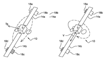
- FIGS. 3 a , 3 b and 3 c schematically represent implementation examples of the flaps 18 so as to obtain torques around three independent axes, in the case of the device illustrated by FIGS. 2 a to 2 c.
- each surface 16 whose optical properties can be commanded can take two different optical states: an absorbent state and a reflective state, the norm of a force generated by solar pressure on a surface 16 being greater when said surface is reflective than when it is absorbent.
- a cross-hatched flap corresponds to a surface whose optical properties can be commanded in the absorbent state; a non-cross-hatched flap corresponds to a surface whose optical properties can be commanded in the reflective state.
- the flaps of solar generator 14 a are designated by first flap 18 a and second flap 18 b
- the flaps of solar generator 14 b are designated by third flap 18 c and fourth flap 18 d
- the first flap 18 a and the fourth flap 18 d are on the same side of the satellite 10 with respect to the Y rotation axis of the solar generators 14 a , 14 b
- the second flap 18 b and the third flap 18 c are on the other side of the satellite 10 with respect to the Y axis (on the right in the figures).
- FIG. 3 a illustrates the utilization of flaps 18 a , 18 b , 18 c , 18 d to create mainly a torque around axis I S .
- a torque around axis I S is, for example, obtained by commanding the surfaces 16 such that the first flap 18 a and the second flap 18 b are placed in a reflective state while the third flap 18 c and the fourth flap 18 d are placed in an absorbent state.
- Such a utilization of the flaps tends to produce rotation in the direction of the dashed arrow (the opposite direction being obtained by inversing the absorbent and reflective states of the flaps).
- FIG. 3 b illustrates the utilization of the flaps 18 a , 18 b , 18 c , 18 d to create mainly a torque around an axis parallel to the Y rotation axis of the solar generators 14 a , 14 b .
- a torque is, for example, obtained by commanding the surfaces 16 such that the first flap 18 a and the fourth flap 18 d are placed in an absorbent state, while the second flap 18 b and the third flap 18 c are placed in a reflective state.
- Such a utilization of the flaps tends to make the satellite rotate in the direction of the dashed arrow (the opposite direction being obtained by inversing the absorbent and reflective states of the flaps).
- FIG. 3 c illustrates the utilization of the flaps 18 a , 18 b , 18 c , 18 d to create mainly a torque around axis D S , known under the name of solar windmill torque.
- a torque is, for example, obtained by commanding the surfaces 16 such that the first flap 18 a and the third flap 18 c are placed in an absorbent state, while the second flap 18 b and the fourth flap 18 d are placed in a reflective state.
- Such a utilization of the flaps tends to make the satellite rotate in the direction of the dashed arrow (the opposite direction being obtained by inversing the absorbent and reflective states of the flaps).
- the device according to the invention is adapted to create torques around three independent axes without having to de-point the solar generators, which can remain pointed in the direction D S throughout the attitude control period, avoiding the drop in electrical energy associated to a de-pointing of said solar generators 14 a , 14 b.
- FIGS. 4 a , 4 b and 4 c respectively represent estimates of the torque capacities (i.e. maximum torques that can be created) for axes I S , Y and D S respectively, designated in these figures by M I , M Y and M D .
- These figures show the influence of the value ⁇ of the inclination, the same for all the flaps 18 , on the torque capacity of the attitude control device.
- the surfaces 16 whose optical properties can be commanded are considered to be made of an electrochromic material allowing a transition from a transparent state to an opaque state.
- the flaps 18 are preferably inclined, in the operating position, at an angle with a constant value ⁇ between 5° and 45°.
- the flaps 18 are inclined at an angle with a constant value ⁇ between 5° and 20°. Such an inclination makes it possible to boost the torque capacity around axis I S , which is advantageous because the predominant disturbing torques are around axis I S .
- each flap 18 of the attitude control device has a constant inclination of 15° with respect to the front face 140 of the solar generator 14 a , 14 b to which it is connected.
- the inclination will preferably be a constant value ⁇ between ⁇ 5° and ⁇ 45° (or even between ⁇ 5° and ⁇ 20°).
- this is equivalent to a constant inclination with an absolute value between 5° and 45°, preferably between 5° and 20°.
- the torque capacity around the axes I S and Y increases as the distance of the flaps 18 to these axes increases. It is therefore understood in particular that the flaps 18 are preferably arranged close to a terminal extremity 144 of a solar generator opposite to the extremity 142 connecting this solar generator to the central body 12 of the satellite 10 , i.e. closer to said terminal extremity than said connection extremity 142 .
- the flaps 18 are, for example, arranged close to the corners of the solar generators 14 a , 14 b .
- flaps 18 allows the surfaces 16 whose optical properties can be commanded to be positioned farther from the Y axis, which makes it possible to increase the torque capacity compared to surfaces 16 with optical properties arranged on the front faces 140 of the solar generators 14 a , 14 b.
- FIGS. 5 a , 5 b and 5 c schematically represent a preferred embodiment variant of the device, compatible with all the embodiments of said device.
- each surface 16 whose optical properties can be commanded comprises a network of cells 160 whose optical properties can be commanded, and the command module is adapted to command separately each cell whose optical properties can be commanded.
- Using a network of cells 160 whose optical properties can be commanded makes it possible to increase the number of possible optical states for each surface 16 . It is indeed understood that if a surface 16 comprises N cells whose optical properties can be commanded having two optical states, said surface 16 may be placed in many different optical states (of the order of N+1 optical states).
- FIGS. 5 a , 5 b and 5 c schematically represent three embodiments of this variant.
- the network is one-dimensional.
- the cells 160 are arranged in lines substantially orthogonal to one side of the solar generator 14 a .
- the cells 160 are arranged in columns substantially parallel to one side of the solar generator 14 a .
- the network of cells 160 is a matrix.
- the surfaces 16 whose optical properties can be commanded are made from an electrochromic material.
- electrochromic materials are considered to be known to the man skilled in the art, and examples of suitable materials are marketed in particular by Eclipse Energy Systems and Ashwin-Ushas Corporation.
- Such electrochromic materials have at least two optical states, and a transition from one optical state to another is achieved by applying a suitable electrical stimulus to them.
- Different types of electrochromic material are available, making it possible to obtain the following transitions in particular:
- some optical states are obtained by combining an electrochromic material with another material.
- a transition from absorbent opaque to reflective opaque can be obtained by placing a film of Type 1 electrochromic material on a reflective opaque material (aluminum, etc.).
- the surfaces 16 with optical properties can be commanded mechanically.
- a surface whose optical properties can be commanded is realized with:
- FIGS. 6 a , 6 b and 6 c represent very schematically a preferred embodiment of such surfaces 16 whose optical properties can be mechanically commanded.
- the surfaces whose optical properties can be commanded are arranged on lateral flaps 18 that, in the operating position, are fixed with respect to the solar generators. Only one lateral flap 18 is shown in these figures.
- the means of mechanically modifying the optical properties mainly comprise two substantially parallel rollers 162 a , 162 b .
- the rollers 162 a , 162 b are mobile in rotation and arranged on two opposite sides of a frame 164 .
- the means of mechanically modifying the optical properties also comprise a means of driving at least one of the rollers in rotation, such as an electric stepping motor (not shown in the figures) commanded by the command module of the device.
- the flap 18 further comprises an element with static optical properties mainly constituted of a band 166 surrounding the rollers 162 a , 162 b , for example a band made of polyimide.
- a band 166 surrounding the rollers 162 a , 162 b
- One portion of the band 166 is oriented towards the front of the solar generator 14 a and is exposed to the Sun's rays, while another portion of said band is oriented towards the rear of the solar generator 14 a and is not exposed to the Sun's rays.
- the rotation of at least one roller 162 a , 162 b drives the scrolling of the band 166 according to a scrolling direction D.
- the band 166 comprises two areas with different static optical properties, for example a black area (cross-hatched area in FIGS. 6 a to 6 c ) and a white area (not cross-hatched in FIGS. 6 a to 6 c ).
- Each area occupies, for example, half of the total surface of the band 166 , and preferably extends over the entire width (considered transversally to the scrolling direction D) of said band.
- the scrolling of the band 166 results in the scrolling of the black and white areas, and varies the proportion of black area and white area in the portion of the band 166 exposed to the Sun's rays.
- This variation in the black area/white area proportion exposed to the Sun's rays makes it possible to vary the optical properties of the portion of the band 166 exposed to the Sun's rays.
- the surface whose optical properties can be commanded corresponds to the portion of the band 166 exposed to the Sun's rays.
- the surfaces whose optical properties can be commanded can be produced with other types of materials.
- surfaces whose optical properties can be commanded realized with liquid crystal screens can be cited.
- FIG. 7 represents the main steps of a method for commanding a satellite 10 comprising a device according to the invention, which are:
- the optimum orientation set point does not necessarily correspond to a normal incidence of the Sun's rays on the solar generators 14 a , 14 b.
- the optical properties of the surfaces 16 are modulated over time so as to be able to obtain an optical state corresponding to a weighted mean of the instantaneous optical states available for said surfaces.
- reflectivity values between ⁇ 1 and ⁇ 2 can be obtained by modifying, during a predefined time interval of duration T 0 , the durations during which the surface 16 has a reflectivity ⁇ 1 (duration ⁇ ) and a reflectivity ⁇ 2 (duration T 0 ⁇ ): the mean reflectivity over the interval of duration T 0 is then equal to ( ⁇ 1 ⁇ + ⁇ 2 ⁇ (T 0 ⁇ ))/T 0 .
- the present invention therefore proposes a device adapted to control the attitude of a satellite 10 around three independent axes, exploiting solar pressure, and not requiring solar generators to be de-pointed with respect to the Sun.
- This device is used to control the attitude of the satellite 10 , i.e. to perform at least one of the following operations:
Landscapes
- Engineering & Computer Science (AREA)
- Remote Sensing (AREA)
- Chemical & Material Sciences (AREA)
- Combustion & Propulsion (AREA)
- Aviation & Aerospace Engineering (AREA)
- Radar, Positioning & Navigation (AREA)
- Life Sciences & Earth Sciences (AREA)
- Sustainable Development (AREA)
- Sustainable Energy (AREA)
- Automation & Control Theory (AREA)
- Photovoltaic Devices (AREA)
Abstract
Description
-
- on flaps connected to solar generators, each flap being destined to occupy a fixed position with respect to the solar generator to which it is connected, and
- such that at least two of said surfaces whose optical properties can be commanded are not parallel when the front faces of the solar generators are optimally oriented with respect to the Sun.
-
- the device comprises at least four flaps having substantially flat surfaces whose optical properties can be commanded, each of these surfaces being destined to have a constant inclination with respect to the front face of the solar generator to which it is connected;
- the absolute value of the inclination, between each flap's surface whose optical properties can be commanded and the front face of the solar generator to which said flap is connected, is between 5° and 45°, preferably between 5° and 20°;
- the flaps of one pair of a solar generator's flaps are destined to have substantially the same inclination with respect to said solar generator's front face;
- at least one surface whose optical properties can be commanded comprises an electrochromic material, preferably an electrochromic material that can take at least two optical states;
- at least one surface whose optical properties can be commanded comprises a network of several cells whose optical properties can be commanded, the command module being destined to command each cell whose optical properties can be commanded separately;
- at least one surface whose optical properties can be commanded is realized with an element having static optical properties, the element with static optical properties comprising at least two areas with different static optical properties, and with means of mechanically modifying the respective proportion of each of the at least two areas with different static optical properties in the portion of the element with static optical properties that is exposed to the Sun's rays;
- the element with static optical properties is a band, and the device comprises at least one roller whose rotation causes the scrolling of the band and the modification of the respective proportion of each of the at least two areas with different static optical properties in the portion of the band exposed to the Sun's rays.
-
- determining an optimum orientation of the front faces of the solar generators with respect to the Sun,
- orienting the front faces of the solar generators according to the optimum orientation,
- determining a torque to be formed around three independent axes for controlling the attitude of the satellite,
- commanding the optical properties of the surfaces whose optical properties can be commanded so as to form said attitude control torques while keeping the front faces of the solar generators in their optimum orientation.
-
- Type 1: transition from transparent to absorbent opaque,
- Type 2: transition from transparent to reflective opaque,
- Type 3: transition from absorbent opaque to reflective opaque.
-
- an element with static optical properties (i.e. substantially fixed over time), said element with static optical properties comprising at least two areas with different static optical properties,
- means of mechanically modifying the optical properties by modifying the respective proportion of each of the at least two areas with different static optical properties in the portion of the element with static optical properties that is exposed to the Sun's rays.
-
- 70 determining an optimum orientation of the front faces 140 of the
solar generators - 72 orienting the front faces 140 of the
solar generators - 74 determining a torque to be created around three independent axes for controlling the attitude of the
satellite 10, - 76 commanding the optical properties of the
surfaces 16 whose optical properties can be commanded so as to create the attitude control torques determined instep 74 while keeping the front faces 140 of thesolar generators
- 70 determining an optimum orientation of the front faces 140 of the
-
- continuously compensate fully or partially for disturbing torques induced by solar pressure or other disturbing effects,
- de-saturate reaction wheels accumulating undesirable angular momentum,
- create torques to modify the attitude of the
satellite 10.
Claims (17)
Applications Claiming Priority (3)
| Application Number | Priority Date | Filing Date | Title |
|---|---|---|---|
| FR1100217A FR2970701B1 (en) | 2011-01-25 | 2011-01-25 | SATELLITE ATTITUDE CONTROL DEVICE AND METHOD FOR CONTROLLING A SATELLITE EMBEDDING SAID DEVICE |
| FR1100217 | 2011-01-25 | ||
| PCT/EP2012/051121 WO2012101162A1 (en) | 2011-01-25 | 2012-01-25 | Device for monitoring the attitude of a satellite, and method for controlling a satellite provided with said device |
Publications (2)
| Publication Number | Publication Date |
|---|---|
| US20130292518A1 US20130292518A1 (en) | 2013-11-07 |
| US9227740B2 true US9227740B2 (en) | 2016-01-05 |
Family
ID=45509523
Family Applications (1)
| Application Number | Title | Priority Date | Filing Date |
|---|---|---|---|
| US13/980,667 Active 2032-09-08 US9227740B2 (en) | 2011-01-25 | 2012-01-25 | Device for monitoring the attitude of a satellite, and method for controlling a satellite provided with said device |
Country Status (4)
| Country | Link |
|---|---|
| US (1) | US9227740B2 (en) |
| EP (1) | EP2643215B1 (en) |
| FR (1) | FR2970701B1 (en) |
| WO (1) | WO2012101162A1 (en) |
Families Citing this family (16)
| Publication number | Priority date | Publication date | Assignee | Title |
|---|---|---|---|---|
| FR2980176A1 (en) * | 2011-09-19 | 2013-03-22 | Astrium Sas | SATELLITE ATTITUDE CONTROL METHOD AND ATTITUDE CONTROL SATELLITE |
| JP2015074376A (en) * | 2013-10-10 | 2015-04-20 | 三菱重工業株式会社 | Artificial satellite and synthetic aperture radar |
| JP7011115B2 (en) | 2016-02-29 | 2022-02-10 | ルギャルド,インク. | Foldable RF membrane antenna |
| EP3950512B1 (en) * | 2016-05-05 | 2025-02-19 | L'garde, Inc. | Solar sail for orbital maneuvers |
| WO2017192200A1 (en) | 2016-05-05 | 2017-11-09 | The Research Foundation For The State Unversity Of New York | Compositions for treating periodontitis and dental calculus accumulation |
| FR3052269B1 (en) * | 2016-06-03 | 2018-07-06 | Thales | METHOD FOR CONTROLLING THE ATTITUDE OF A SPATIAL VEHICLE, COMPUTER PROGRAM PRODUCT AND CONTROL MODULE THEREFOR |
| CN106828980B (en) * | 2016-11-21 | 2019-06-07 | 上海卫星工程研究所 | The big disturbance torque real-time compensation method of payload sweep mechanism on star |
| KR101898641B1 (en) * | 2017-08-16 | 2018-10-31 | 한국항공우주연구원 | Satellite and method for controlling the same |
| JP7605632B2 (en) | 2018-02-15 | 2024-12-24 | ルギャルド,インク. | Space Debris Engagement and Deorbit System |
| US20210284361A1 (en) * | 2019-07-17 | 2021-09-16 | Skeyeon, Inc. | Systems and methods for attitude control for a satellite |
| EP4022713A4 (en) | 2019-08-30 | 2023-08-23 | L'garde, Inc. | COMPACTABLE ANTENNA FOR SATELLITE COMMUNICATIONS |
| EP4110698A4 (en) | 2020-02-24 | 2024-02-14 | L'garde, Inc. | Connection assembly |
| JP7426714B2 (en) * | 2020-07-15 | 2024-02-02 | 国立研究開発法人宇宙航空研究開発機構 | Optical devices and spacecraft using them |
| US11973258B2 (en) | 2020-10-14 | 2024-04-30 | L'garde, Inc. | Compactable structures for deployment in space |
| CN112462712B (en) * | 2020-11-25 | 2022-03-04 | 中国人民解放军63920部队 | Multi-spacecraft main and auxiliary sequence cooperative control system and method |
| US12549126B2 (en) | 2021-11-12 | 2026-02-10 | L'garde, Inc. | Lightweight, low stow volume, deployable solar concentrator for space applications |
Citations (13)
| Publication number | Priority date | Publication date | Assignee | Title |
|---|---|---|---|---|
| DE2537577A1 (en) | 1975-08-22 | 1977-03-03 | Michael Dipl Ing Truemper | Position regulation of geosynchronous or geostationary satellites - using two or more mirrors exposed to sun radiation for independence from propellant supply carried |
| US5133518A (en) * | 1989-12-29 | 1992-07-28 | Societe Nationale Industrielle Et Aerospatiale | Attitude control device using solar sails for a satellite stabilized on three axes |
| US5305971A (en) | 1992-07-14 | 1994-04-26 | Trw Inc. | Spacecraft control by electrochromic devices |
| EP0668212A1 (en) | 1994-02-16 | 1995-08-23 | Hughes Aircraft Company | Optical satellite attitude control system |
| DE19637262A1 (en) | 1995-09-14 | 1997-03-20 | Matra Marconi Space France | Spacecraft control process to direct it against sun |
| EP0794120A1 (en) | 1996-03-05 | 1997-09-10 | HE HOLDINGS, INC. dba HUGHES ELECTRONICS | Controlled-emission solar tabs for attitude solar sailing |
| EP0919463A1 (en) * | 1997-11-25 | 1999-06-02 | ICO Services Ltd. | Spacecraft attitude control |
| US6102336A (en) * | 1997-06-25 | 2000-08-15 | Agence Spatiale Europeenne | Passive device for stabilizing the direction in which a spacecraft points |
| US20060038080A1 (en) * | 2002-12-12 | 2006-02-23 | Bernard Polle | Solar control method for spacecraft |
| US7104506B1 (en) * | 2003-08-06 | 2006-09-12 | Lockheed Martin Corporation | Spacecraft disturbance trimming system |
| US7973236B2 (en) * | 2008-06-06 | 2011-07-05 | Lockheed Martin Corporation | Optical shutter for improved photovoltaic array thermal performance |
| US7980514B2 (en) * | 2008-03-14 | 2011-07-19 | Northrop Grumman Space & Mission Systems Corp. | Solar array momentum control |
| US8547669B2 (en) * | 2011-01-12 | 2013-10-01 | Schneider Electric USA, Inc. | Arc fault mitigation for photovoltaic systems |
-
2011
- 2011-01-25 FR FR1100217A patent/FR2970701B1/en not_active Expired - Fee Related
-
2012
- 2012-01-25 US US13/980,667 patent/US9227740B2/en active Active
- 2012-01-25 EP EP12700716.9A patent/EP2643215B1/en not_active Not-in-force
- 2012-01-25 WO PCT/EP2012/051121 patent/WO2012101162A1/en not_active Ceased
Patent Citations (14)
| Publication number | Priority date | Publication date | Assignee | Title |
|---|---|---|---|---|
| DE2537577A1 (en) | 1975-08-22 | 1977-03-03 | Michael Dipl Ing Truemper | Position regulation of geosynchronous or geostationary satellites - using two or more mirrors exposed to sun radiation for independence from propellant supply carried |
| US5133518A (en) * | 1989-12-29 | 1992-07-28 | Societe Nationale Industrielle Et Aerospatiale | Attitude control device using solar sails for a satellite stabilized on three axes |
| US5305971A (en) | 1992-07-14 | 1994-04-26 | Trw Inc. | Spacecraft control by electrochromic devices |
| EP0668212A1 (en) | 1994-02-16 | 1995-08-23 | Hughes Aircraft Company | Optical satellite attitude control system |
| DE19637262A1 (en) | 1995-09-14 | 1997-03-20 | Matra Marconi Space France | Spacecraft control process to direct it against sun |
| US5775645A (en) * | 1996-03-05 | 1998-07-07 | Hughes Electronics Corporation | Controlled-emission solar tabs for attitude solar sailing |
| EP0794120A1 (en) | 1996-03-05 | 1997-09-10 | HE HOLDINGS, INC. dba HUGHES ELECTRONICS | Controlled-emission solar tabs for attitude solar sailing |
| US6102336A (en) * | 1997-06-25 | 2000-08-15 | Agence Spatiale Europeenne | Passive device for stabilizing the direction in which a spacecraft points |
| EP0919463A1 (en) * | 1997-11-25 | 1999-06-02 | ICO Services Ltd. | Spacecraft attitude control |
| US20060038080A1 (en) * | 2002-12-12 | 2006-02-23 | Bernard Polle | Solar control method for spacecraft |
| US7104506B1 (en) * | 2003-08-06 | 2006-09-12 | Lockheed Martin Corporation | Spacecraft disturbance trimming system |
| US7980514B2 (en) * | 2008-03-14 | 2011-07-19 | Northrop Grumman Space & Mission Systems Corp. | Solar array momentum control |
| US7973236B2 (en) * | 2008-06-06 | 2011-07-05 | Lockheed Martin Corporation | Optical shutter for improved photovoltaic array thermal performance |
| US8547669B2 (en) * | 2011-01-12 | 2013-10-01 | Schneider Electric USA, Inc. | Arc fault mitigation for photovoltaic systems |
Non-Patent Citations (2)
| Title |
|---|
| International Search Report dated Apr. 26, 2012; corresponding to PCT/EP2012/051121. |
| Kyroudis; "Survey of Solar-Sailing Configurations for Satellite Attitude Control"; Paper American Astronautical Society; vol. 91-486; Jan. 1, 1991; pp. 815-838; XP000671524. |
Also Published As
| Publication number | Publication date |
|---|---|
| FR2970701B1 (en) | 2015-04-17 |
| US20130292518A1 (en) | 2013-11-07 |
| FR2970701A1 (en) | 2012-07-27 |
| EP2643215B1 (en) | 2014-12-17 |
| EP2643215A1 (en) | 2013-10-02 |
| WO2012101162A1 (en) | 2012-08-02 |
Similar Documents
| Publication | Publication Date | Title |
|---|---|---|
| US9227740B2 (en) | Device for monitoring the attitude of a satellite, and method for controlling a satellite provided with said device | |
| CN103917451B (en) | Method for adjusting satellite attitude and attitude-controlled satellite | |
| EP0436425B1 (en) | Attitude control system provided by solar sails for a satellite stabilized around three axes | |
| US5305971A (en) | Spacecraft control by electrochromic devices | |
| EP0519038B1 (en) | Method for controlling the pitch attitude of a satellite by means of solar radiation pressure, and a satellite, for implementing same | |
| US20060011783A1 (en) | Method for controlling the attitude of an satellites in elliptic orbits using solar radiation pressure | |
| US11155369B2 (en) | Artificial satellite and method of controlling the same | |
| US6921050B2 (en) | Solar torque control using thin film directionally reflective, emissive, absorptive and transmissive surfaces | |
| US20130126668A1 (en) | Balloon Comprising Photovoltaic Means and a Solar Concentration Device | |
| JPS5912000A (en) | Method of maintaining station northern and southern axis of artificial satellite in equator plane | |
| JPH02262500A (en) | satellite control system | |
| ES2748908T3 (en) | Efficient station maintenance design for mixed fuel systems in response to failure of an electric drive | |
| Zhang et al. | Solar sail attitude control using shape variation of booms | |
| US6070833A (en) | Methods for reducing solar array power variations while managing the system influences of operating with off-pointed solar wings | |
| Luo et al. | Design concept for a solar sail with individually controllable elements | |
| JP2001072000A (en) | A method for stationkeeping maneuvering of spacecraft using reflection of solar radiation pressure | |
| EP1569847B1 (en) | Solar control method for spacecraft | |
| EP0919463A1 (en) | Spacecraft attitude control | |
| McInnes | Solar sailing: a new tool for solar system research | |
| JPH0299498A (en) | Disturbance torque control device | |
| JPH11152097A (en) | Artificial satellite | |
| Summerer et al. | Making the first steps towards solar power from space-microgravity experiments testing the deployment of large antennas | |
| WO1998032657A1 (en) | Spacecraft attitude control system using low thrust thrusters | |
| FR2711111A1 (en) | Spacecraft with solar sail and method for piloting such a craft | |
| Toyota et al. | Status of Power System of AKATSUKI to be Inserted into Orbit around Venus |
Legal Events
| Date | Code | Title | Description |
|---|---|---|---|
| AS | Assignment |
Owner name: ASTRIIUM SAS, FRANCE Free format text: ASSIGNMENT OF ASSIGNORS INTEREST;ASSIGNORS:LAGADEC, KRISTEN;CHABOT, THOMAS;SIGNING DATES FROM 20130705 TO 20130708;REEL/FRAME:030838/0877 |
|
| AS | Assignment |
Owner name: ASTRIUM SAS, FRANCE Free format text: ASSIGNMENT OF ASSIGNORS INTEREST;ASSIGNORS:LAGADEC, KRISTEN;CHABOT, THOMAS;SIGNING DATES FROM 20130705 TO 20130708;REEL/FRAME:036688/0902 |
|
| AS | Assignment |
Owner name: AIRBUS DEFENCE AND SPACE SAS, FRANCE Free format text: CHANGE OF NAME;ASSIGNOR:ASTRIUM SAS;REEL/FRAME:037176/0837 Effective date: 20140701 |
|
| STCF | Information on status: patent grant |
Free format text: PATENTED CASE |
|
| MAFP | Maintenance fee payment |
Free format text: PAYMENT OF MAINTENANCE FEE, 4TH YEAR, LARGE ENTITY (ORIGINAL EVENT CODE: M1551); ENTITY STATUS OF PATENT OWNER: LARGE ENTITY Year of fee payment: 4 |
|
| MAFP | Maintenance fee payment |
Free format text: PAYMENT OF MAINTENANCE FEE, 8TH YEAR, LARGE ENTITY (ORIGINAL EVENT CODE: M1552); ENTITY STATUS OF PATENT OWNER: LARGE ENTITY Year of fee payment: 8 |