US9227503B1 - Electric power split hybrid system - Google Patents
Electric power split hybrid system Download PDFInfo
- Publication number
- US9227503B1 US9227503B1 US14/507,804 US201414507804A US9227503B1 US 9227503 B1 US9227503 B1 US 9227503B1 US 201414507804 A US201414507804 A US 201414507804A US 9227503 B1 US9227503 B1 US 9227503B1
- Authority
- US
- United States
- Prior art keywords
- engine
- electric power
- motor
- gear
- generator
- Prior art date
- Legal status (The legal status is an assumption and is not a legal conclusion. Google has not performed a legal analysis and makes no representation as to the accuracy of the status listed.)
- Active
Links
Images


Classifications
-
- B—PERFORMING OPERATIONS; TRANSPORTING
- B60—VEHICLES IN GENERAL
- B60K—ARRANGEMENT OR MOUNTING OF PROPULSION UNITS OR OF TRANSMISSIONS IN VEHICLES; ARRANGEMENT OR MOUNTING OF PLURAL DIVERSE PRIME-MOVERS IN VEHICLES; AUXILIARY DRIVES FOR VEHICLES; INSTRUMENTATION OR DASHBOARDS FOR VEHICLES; ARRANGEMENTS IN CONNECTION WITH COOLING, AIR INTAKE, GAS EXHAUST OR FUEL SUPPLY OF PROPULSION UNITS IN VEHICLES
- B60K6/00—Arrangement or mounting of plural diverse prime-movers for mutual or common propulsion, e.g. hybrid propulsion systems comprising electric motors and internal combustion engines
- B60K6/20—Arrangement or mounting of plural diverse prime-movers for mutual or common propulsion, e.g. hybrid propulsion systems comprising electric motors and internal combustion engines the prime-movers consisting of electric motors and internal combustion engines, e.g. HEVs
- B60K6/42—Arrangement or mounting of plural diverse prime-movers for mutual or common propulsion, e.g. hybrid propulsion systems comprising electric motors and internal combustion engines the prime-movers consisting of electric motors and internal combustion engines, e.g. HEVs characterised by the architecture of the hybrid electric vehicle
- B60K6/44—Series-parallel type
- B60K6/442—Series-parallel switching type
-
- B—PERFORMING OPERATIONS; TRANSPORTING
- B60—VEHICLES IN GENERAL
- B60K—ARRANGEMENT OR MOUNTING OF PROPULSION UNITS OR OF TRANSMISSIONS IN VEHICLES; ARRANGEMENT OR MOUNTING OF PLURAL DIVERSE PRIME-MOVERS IN VEHICLES; AUXILIARY DRIVES FOR VEHICLES; INSTRUMENTATION OR DASHBOARDS FOR VEHICLES; ARRANGEMENTS IN CONNECTION WITH COOLING, AIR INTAKE, GAS EXHAUST OR FUEL SUPPLY OF PROPULSION UNITS IN VEHICLES
- B60K6/00—Arrangement or mounting of plural diverse prime-movers for mutual or common propulsion, e.g. hybrid propulsion systems comprising electric motors and internal combustion engines
- B60K6/20—Arrangement or mounting of plural diverse prime-movers for mutual or common propulsion, e.g. hybrid propulsion systems comprising electric motors and internal combustion engines the prime-movers consisting of electric motors and internal combustion engines, e.g. HEVs
- B60K6/22—Arrangement or mounting of plural diverse prime-movers for mutual or common propulsion, e.g. hybrid propulsion systems comprising electric motors and internal combustion engines the prime-movers consisting of electric motors and internal combustion engines, e.g. HEVs characterised by apparatus, components or means specially adapted for HEVs
- B60K6/36—Arrangement or mounting of plural diverse prime-movers for mutual or common propulsion, e.g. hybrid propulsion systems comprising electric motors and internal combustion engines the prime-movers consisting of electric motors and internal combustion engines, e.g. HEVs characterised by apparatus, components or means specially adapted for HEVs characterised by the transmission gearings
- B60K6/365—Arrangement or mounting of plural diverse prime-movers for mutual or common propulsion, e.g. hybrid propulsion systems comprising electric motors and internal combustion engines the prime-movers consisting of electric motors and internal combustion engines, e.g. HEVs characterised by apparatus, components or means specially adapted for HEVs characterised by the transmission gearings with the gears having orbital motion
-
- B—PERFORMING OPERATIONS; TRANSPORTING
- B60—VEHICLES IN GENERAL
- B60K—ARRANGEMENT OR MOUNTING OF PROPULSION UNITS OR OF TRANSMISSIONS IN VEHICLES; ARRANGEMENT OR MOUNTING OF PLURAL DIVERSE PRIME-MOVERS IN VEHICLES; AUXILIARY DRIVES FOR VEHICLES; INSTRUMENTATION OR DASHBOARDS FOR VEHICLES; ARRANGEMENTS IN CONNECTION WITH COOLING, AIR INTAKE, GAS EXHAUST OR FUEL SUPPLY OF PROPULSION UNITS IN VEHICLES
- B60K6/00—Arrangement or mounting of plural diverse prime-movers for mutual or common propulsion, e.g. hybrid propulsion systems comprising electric motors and internal combustion engines
- B60K6/20—Arrangement or mounting of plural diverse prime-movers for mutual or common propulsion, e.g. hybrid propulsion systems comprising electric motors and internal combustion engines the prime-movers consisting of electric motors and internal combustion engines, e.g. HEVs
- B60K6/22—Arrangement or mounting of plural diverse prime-movers for mutual or common propulsion, e.g. hybrid propulsion systems comprising electric motors and internal combustion engines the prime-movers consisting of electric motors and internal combustion engines, e.g. HEVs characterised by apparatus, components or means specially adapted for HEVs
- B60K6/38—Arrangement or mounting of plural diverse prime-movers for mutual or common propulsion, e.g. hybrid propulsion systems comprising electric motors and internal combustion engines the prime-movers consisting of electric motors and internal combustion engines, e.g. HEVs characterised by apparatus, components or means specially adapted for HEVs characterised by the driveline clutches
- B60K6/383—One-way clutches or freewheel devices
-
- B—PERFORMING OPERATIONS; TRANSPORTING
- B60—VEHICLES IN GENERAL
- B60K—ARRANGEMENT OR MOUNTING OF PROPULSION UNITS OR OF TRANSMISSIONS IN VEHICLES; ARRANGEMENT OR MOUNTING OF PLURAL DIVERSE PRIME-MOVERS IN VEHICLES; AUXILIARY DRIVES FOR VEHICLES; INSTRUMENTATION OR DASHBOARDS FOR VEHICLES; ARRANGEMENTS IN CONNECTION WITH COOLING, AIR INTAKE, GAS EXHAUST OR FUEL SUPPLY OF PROPULSION UNITS IN VEHICLES
- B60K6/00—Arrangement or mounting of plural diverse prime-movers for mutual or common propulsion, e.g. hybrid propulsion systems comprising electric motors and internal combustion engines
- B60K6/20—Arrangement or mounting of plural diverse prime-movers for mutual or common propulsion, e.g. hybrid propulsion systems comprising electric motors and internal combustion engines the prime-movers consisting of electric motors and internal combustion engines, e.g. HEVs
- B60K6/22—Arrangement or mounting of plural diverse prime-movers for mutual or common propulsion, e.g. hybrid propulsion systems comprising electric motors and internal combustion engines the prime-movers consisting of electric motors and internal combustion engines, e.g. HEVs characterised by apparatus, components or means specially adapted for HEVs
- B60K6/40—Arrangement or mounting of plural diverse prime-movers for mutual or common propulsion, e.g. hybrid propulsion systems comprising electric motors and internal combustion engines the prime-movers consisting of electric motors and internal combustion engines, e.g. HEVs characterised by apparatus, components or means specially adapted for HEVs characterised by the assembly or relative disposition of components
-
- B—PERFORMING OPERATIONS; TRANSPORTING
- B60—VEHICLES IN GENERAL
- B60K—ARRANGEMENT OR MOUNTING OF PROPULSION UNITS OR OF TRANSMISSIONS IN VEHICLES; ARRANGEMENT OR MOUNTING OF PLURAL DIVERSE PRIME-MOVERS IN VEHICLES; AUXILIARY DRIVES FOR VEHICLES; INSTRUMENTATION OR DASHBOARDS FOR VEHICLES; ARRANGEMENTS IN CONNECTION WITH COOLING, AIR INTAKE, GAS EXHAUST OR FUEL SUPPLY OF PROPULSION UNITS IN VEHICLES
- B60K6/00—Arrangement or mounting of plural diverse prime-movers for mutual or common propulsion, e.g. hybrid propulsion systems comprising electric motors and internal combustion engines
- B60K6/20—Arrangement or mounting of plural diverse prime-movers for mutual or common propulsion, e.g. hybrid propulsion systems comprising electric motors and internal combustion engines the prime-movers consisting of electric motors and internal combustion engines, e.g. HEVs
- B60K6/42—Arrangement or mounting of plural diverse prime-movers for mutual or common propulsion, e.g. hybrid propulsion systems comprising electric motors and internal combustion engines the prime-movers consisting of electric motors and internal combustion engines, e.g. HEVs characterised by the architecture of the hybrid electric vehicle
- B60K6/44—Series-parallel type
- B60K6/445—Differential gearing distribution type
-
- B—PERFORMING OPERATIONS; TRANSPORTING
- B62—LAND VEHICLES FOR TRAVELLING OTHERWISE THAN ON RAILS
- B62K—CYCLES; CYCLE FRAMES; CYCLE STEERING DEVICES; RIDER-OPERATED TERMINAL CONTROLS SPECIALLY ADAPTED FOR CYCLES; CYCLE AXLE SUSPENSIONS; CYCLE SIDE-CARS, FORECARS, OR THE LIKE
- B62K11/00—Motorcycles, engine-assisted cycles or motor scooters with one or two wheels
-
- B—PERFORMING OPERATIONS; TRANSPORTING
- B62—LAND VEHICLES FOR TRAVELLING OTHERWISE THAN ON RAILS
- B62M—RIDER PROPULSION OF WHEELED VEHICLES OR SLEDGES; POWERED PROPULSION OF SLEDGES OR SINGLE-TRACK CYCLES; TRANSMISSIONS SPECIALLY ADAPTED FOR SUCH VEHICLES
- B62M23/00—Transmissions characterised by use of other elements; Other transmissions
- B62M23/02—Transmissions characterised by use of other elements; Other transmissions characterised by the use of two or more dissimilar sources of power, e.g. transmissions for hybrid motorcycles
-
- B—PERFORMING OPERATIONS; TRANSPORTING
- B60—VEHICLES IN GENERAL
- B60Y—INDEXING SCHEME RELATING TO ASPECTS CROSS-CUTTING VEHICLE TECHNOLOGY
- B60Y2200/00—Type of vehicle
- B60Y2200/10—Road Vehicles
- B60Y2200/12—Motorcycles, Trikes; Quads; Scooters
-
- Y—GENERAL TAGGING OF NEW TECHNOLOGICAL DEVELOPMENTS; GENERAL TAGGING OF CROSS-SECTIONAL TECHNOLOGIES SPANNING OVER SEVERAL SECTIONS OF THE IPC; TECHNICAL SUBJECTS COVERED BY FORMER USPC CROSS-REFERENCE ART COLLECTIONS [XRACs] AND DIGESTS
- Y02—TECHNOLOGIES OR APPLICATIONS FOR MITIGATION OR ADAPTATION AGAINST CLIMATE CHANGE
- Y02T—CLIMATE CHANGE MITIGATION TECHNOLOGIES RELATED TO TRANSPORTATION
- Y02T10/00—Road transport of goods or passengers
- Y02T10/60—Other road transportation technologies with climate change mitigation effect
- Y02T10/62—Hybrid vehicles
-
- Y—GENERAL TAGGING OF NEW TECHNOLOGICAL DEVELOPMENTS; GENERAL TAGGING OF CROSS-SECTIONAL TECHNOLOGIES SPANNING OVER SEVERAL SECTIONS OF THE IPC; TECHNICAL SUBJECTS COVERED BY FORMER USPC CROSS-REFERENCE ART COLLECTIONS [XRACs] AND DIGESTS
- Y10—TECHNICAL SUBJECTS COVERED BY FORMER USPC
- Y10S—TECHNICAL SUBJECTS COVERED BY FORMER USPC CROSS-REFERENCE ART COLLECTIONS [XRACs] AND DIGESTS
- Y10S903/00—Hybrid electric vehicles, HEVS
- Y10S903/902—Prime movers comprising electrical and internal combustion motors
- Y10S903/903—Prime movers comprising electrical and internal combustion motors having energy storing means, e.g. battery, capacitor
- Y10S903/951—Assembly or relative location of components
Definitions
- the present invention relates to an electric power split hybrid system, particularly with regard to an electric power split hybrid system with a switching part.
- the electric power split hybrid system has advantages and effectiveness of extending battery life and reducing a battery volume to enhance overall fuel economic benefit.
- hybrid motorcycles can now be switched to one of two modes of an electric driving mode (by a motor) and a fuel-driven mode (by an engine). Only one of the two modes is utilized to drive motorcycles at one time. Hence, there are still the following disadvantages.
- the main objective of the present invention is to provide an electric power split hybrid system which has advantages and effectiveness of extending battery life and reducing a battery volume to enhance overall fuel economic benefit, and so on, in order to solve the above mentioned problems of prior techniques, i.e., having a shorter battery life and a large battery volume, and a lower fuel economy benefit, and so on.
- the technical means adopted and used in the present invention for solving the problems depicted above is to provide an electric power split hybrid system, comprising:
- a first one-way clutch which is fixed to the case and is capable of being set in a locked state and in a disengaged state, respectively;
- a second one-way clutch which is fixed to the case and is capable of being set in a locked state and in a disengaged state, respectively;
- a generator which is used to start the engine, and is capable of adjusting a torque of the engine and of generating electricity via driving of the engine;
- a transmission mechanism which is used to link and move a wheel to rotate
- a linkage unit which comprises a transmission element, a driving wheel group, and a passive wheel group, the driving wheel group being connected to the engine, the transmission element is used to link the driving wheel group and the passive wheel group to each other for consecutive movement;
- a planetary gear frame set which comprises a planetary frame, a plurality of planetary gears, a ring gear, and a sun gear
- the planetary frame being connected to the passive wheel group and the first one-way clutch
- the plurality of planetary gears being installed and pivoted to the planetary frame and each of the plurality of planetary gears being respectively engaged with the ring gear and the sun gear
- the ring gear being connected to the transmission mechanism
- the sun gear being connected to the second one-way clutch and the motor
- an electric power part which is used to store electrical energy generated by the generator and to supply electric power to the motor;
- a switching part which is connected to the generator, the motor, and the electric power part, electric power generated by the generator being switched by the switching part to supply to one of the motor and the electric power part.
- FIG. 1 shows a schematic exploded perspective view of an electric power split hybrid system in accordance with the present invention
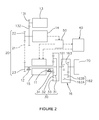
- FIG. 2 shows a schematic linkage diagram of the electric power split hybrid system in accordance with the present invention
- FIG. 3 shows a schematic diagram of a rotational velocity relationship of gears of a planetary gear frame set under a first mode thereof in accordance with the present invention
- FIG. 4 shows a schematic diagram of a rotational velocity relationship of the gears of the planetary gear frame set under a second mode thereof in accordance with the present invention
- FIG. 5 shows a schematic diagram of a relationship between an engine torque and a rotational velocity when the system runs in a middle-speed, high-efficiency status in accordance with the present invention.
- FIG. 6 shows a schematic flow diagram of a rotational velocity relationship of the gears of the planetary gear frame set under a third mode thereof in accordance with the present invention.
- an electric power split hybrid system of the present invention comprises a case 10 , a first one-way clutch 11 , a second one-way clutch 12 , an engine 13 , a generator 14 , a motor 15 , a transmission mechanism 16 , a linkage unit 20 , a planetary gear frame set 30 , an electric power part 40 , and a switching part 50 .
- the first one-way clutch 11 and the second one-way clutch 12 are fixed to the case 10 , and are capable of being set in a locked state and in a disengaged state, respectively.
- they may limit their connective devices for unidirectional rotation of the connective devices, and a rotation direction can be adjustable (i.e., limiting to either forward rotation or backward rotation).
- the engine 13 comprises a first linkage part 131 and a second linkage part 132 , and the first linkage part 131 and the second linkage part 132 are linked to each other for consecutive movement.
- the engine 13 drives the first linkage part 131 to rotate, and the first linkage part 131 consecutively drives the second linkage part 132 to rotate.
- the generator 14 is used to start the engine 13 , and is capable of adjusting a torque of the engine 13 and of generating electricity via driving of the engine 13 .
- the transmission mechanism 16 is used to link and move a wheel 70 to rotate.
- the linkage unit 20 comprises a transmission element 21 , a driving wheel group 22 , and a passive wheel group 23 .
- the driving wheel group 22 is connected to the engine 13
- the transmission element 21 is used to link the driving wheel group 22 and the passive wheel group 23 to each other for consecutive movement.
- the second linkage part 132 of the engine 13 is connected to the generator 14 and the driving wheel group 22 . In other words, when the engine 13 starts, the first linkage part 131 drives the second linkage part 132 to rotate, and the second linkage part 132 drives the generator 14 to generate electricity and drives the driving wheel group 22 to rotate.
- the planetary gear frame set 30 comprises a planetary frame 31 , a plurality of planetary gears 32 , a ring gear 33 , and a sun gear 34 .
- the planetary frame 31 is connected to the passive wheel group 23 and the first one-way clutch 11 .
- the plurality of planetary gears 32 are installed and pivoted to the planetary frame 31 and each of the plurality of planetary gears is respectively engaged with the ring gear 33 and the sun gear 34 .
- the ring gear 33 is connected to the transmission mechanism 16
- the sun gear 34 is connected to the second one-way clutch 12 and the motor 15 .
- the electric power part 40 is used to store electrical energy generated by the generator 14 and to supply electric power to the motor 15 .
- the switching part 50 is connected to the generator 14 , the motor 15 , and the electric power part 40 . Electric power generated by the generator 14 can be switched by the switching part 50 to supply to at least one of the motor 15 and the electric power part 40 .
- presentation of the case 10 therein is mainly to show that the first one-way clutch 11 and the second one-way clutch 12 are fixed onto the case 10 .
- the case 10 is presented around fixed positions of the clutches 11 , 12 .
- the transmission mechanism 16 may be a gear transmission mechanism. As shown in FIG. 2 , the transmission mechanism 16 comprises a first gear 161 , a second gear 162 , and a third gear 163 .
- the second gear 162 comprises a first tooth part 162 A and a second tooth part 162 B, and the first tooth part 162 A and the second tooth part 162 B are coaxial.
- the first gear 161 is connected to the ring gear 33 and is engaged with the first tooth part 162 A of the second gear 162 .
- the second tooth part 162 B is engaged with the third gear 163 .
- the third gear 163 is connected to the wheel 70 .
- the motor 15 starts solely (The engine 13 is off at this moment), the motor 15 is set as backward rotation thereof, and the first one-way clutch 11 is locked.
- a rotational velocity relationship of the planetary gear frame set 30 is as shown in FIG. 3 .
- the planetary frame 31 is stationary because the first one-way clutch 11 is locked, and thus the plurality of planetary gears 32 are consecutively driven by the sun gear 34 to rotate on the planetary frame 31 and drive the ring gear 33 to consecutively rotate.
- the power is transmitted to the transmission mechanism 16 to drive the wheel 70 . It can be learned from FIGS.
- a speed reduction ratio of a rotational velocity transmitted from the motor 15 to the wheel 70 is:
- ⁇ M is a rotational velocity of the motor 15
- ⁇ F is a rotational velocity of the transmission mechanism 16
- ⁇ W is a rotational velocity of the wheel 70
- ⁇ f is a speed reduction ratio of the transmission mechanism 16
- ⁇ p is a ratio of a tooth number of the ring gear 33 and a tooth number of the sun gear 34
- Z r is the tooth number of the ring gear 33
- Z s is the tooth number of the sun gear 34 ;
- a first curve L 1 is a rotational velocity relationship curve of the planetary gear frame set 30 in the low-speed electric mode. It can be learned from the first curve L 1 that, when the first one-way clutch 11 is locked, the rotational velocity ( ⁇ p ) of the planetary frame 31 is zero.
- the rotational velocity ( ⁇ s ) of the sun gear 34 is a rotational velocity of backward rotation
- the rotational velocity ( ⁇ r ) of the ring gear 33 is a rotational velocity of forward rotation.
- the generator 14 starts the engine 13 , and then, the engine 13 (Forward rotation thereof) drives the linkage unit 20 and drives the generator 14 to generate electricity.
- the generated electric power of the generator 14 is output to the motor 15 and the electric power part 40 to further drive the motor 15 to rotate forward and charge the electric power part 40 .
- the first one-way clutch 11 and the second one-way clutch 12 are set to limit unidirectional rotation of their connective devices, respectively, and the limited rotations of their connective devices are in the same direction. In other words, the first one-way clutch 11 and the second one-way clutch 12 allow only for rotations of the first rotation direction S 1 .
- a fourth curve L 4 is a relationship curve of a rotational velocity and a torque.
- a second curve L 2 in FIG. 4 is a rotational velocity relationship curve of ordinary motorcycles in the art to run in a medium and low speed status
- a third curve L 3 is a rotational velocity relationship curve of the planetary gear frame set 30 of the present invention in its medium and low speed switching mode.
- the planetary frame 31 has a rotational velocity of forward rotation ( ⁇ p , driven by the engine 13 ).
- the ring gear 33 has a rotational velocity of forward rotation ( ⁇ r , used to drive the transmission mechanism 16 to move consecutively), and the sun gear 34 has a rotational velocity of forward rotation ( ⁇ s , driven by the motor 15 ).
- a speed reduction ratio of a rotational velocity transmitted from the engine 13 to the wheel 70 is:
- ⁇ ch is a speed reduction ratio of the linkage unit 20 .
- the engine 13 is maintained at a medium-speed and high-efficiency operation, and an output rotational velocity is reduced by power of forward rotation of the motor 15 .
- an output rotational velocity is reduced by power of forward rotation of the motor 15 .
- [3] Electronic continuously variable transmission (e-CVT) mode When the hybrid system run at a medium and high speed (and at a high speed), electric power generated from the generator 14 is only output to the motor 15 by switching of the switching part 50 (No longer charging to the electric power part 40 ).
- the engine 13 rotates forward and the motor 15 rotates backward to add an output rotational velocity of the engine 13 and an output rotational velocity of the motor 15 to each other.
- the first one-way clutch 11 and the second one-way clutch 12 are set to limit unidirectional rotation of their connective devices, respectively, and the limited rotations of their connective devices are in opposite directions (The first one-way clutch 11 allows only for rotations along the first rotation direction S 1 , and the second one-way clutch 12 allows otherwise).
- a rotational velocity relationship of the planetary gear frame set 30 is shown as FIG. 5 .
- a fifth curve L 5 is representative to a rotational velocity relationship curve of the motor 15 , the engine 13 , and the wheel 70 in the e-CVT mode. It can be learned from the fifth curve L 5 that the sun gear 34 is driven by the motor 15 and has a rotational velocity ( ⁇ s ) of backward rotation of the sun gear 34 .
- a rotational velocity ( ⁇ p ) of the planetary frame 31 is a rotational velocity of forward rotation thereof, and a rotational velocity ( ⁇ r ) of the ring gear 33 shows a linear increase (Its rotational velocity varies together with rotational velocity changes of the engine 13 and the motor 15 ).
- the switching part 50 switches and outputs electric power generated by the generator 14 to the motor 15 so that the motor 15 runs by direct use of the electric power generated by the generator 14 .
- the system consumes more fuel. Accordingly, in the present invention, by simultaneous driving of the engine 13 and the motor 15 to add up their output rotational velocities at medium and high speed (or high speed), the rotational velocity of the engine 13 can be therefore reduced to lower fuel consumption thereof.
- the electric power part 40 (i.e., batteries) of the present invention only is charged and discharges respectively in the low-speed electric mode and the medium and low speed switching mode.
- a medium-speed or higher A normal traveling speed is generally a medium-speed or above
- electric power of the motor 15 is directly supplied by the generator 14 after generation thereof.
- the electric power part 40 no longer proceeds to be charged and discharged, and therefore usage of the electric power part 40 (i.e., batteries) is effectively reduced to further increase a service life thereof. Since the usage of the electric power part 40 , i.e., batteries, decreases, a volume thereof can be relatively reduced. Market acceptance will be improved under conditions of a high life and small size of batteries. Differences between the present invention and ordinary technology in the art can be learned from Table 1, FIG. 5 , and following explanations.
- a rotational velocity of a defined low-speed zone V 1 in FIG. 5 is from zero to a first rotational velocity value ⁇ 1
- a rotational velocity of a defined medium and low speed zone V 2 is from the first rotational velocity value ⁇ 1 to a second rotational velocity value ⁇ 2
- a rotational velocity of a defined medium-speed zone V 3 is set from the second rotational velocity value ⁇ 2 to a third rotational velocity value ⁇ 3
- a rotational velocity of a defined medium and high speed zone V 4 is from the third rotational velocity value ⁇ 3 to a fourth rotational velocity value ⁇ 4
- a rotational velocity of a defined high speed zone V 5 is set above the fourth rotational velocity value ⁇ 4 .
- the first rotational velocity value ⁇ 1 is 1,200 rpm
- the second rotational velocity value ⁇ 2 is 2,400 rpm
- the third rotational velocity value ⁇ 3 is 4,800 rpm
- the fourth rotational velocity value ⁇ 4 is 7,200 rpm.
- a ratio of the rotational velocity of the engine 13 and the rotational velocity of the motor 15 driven by the generator 14 in accordance with the present invention is 5:1.
- the present invention is designed to be the same as general technology in the art to have the engine 13 turned off and to provide power for driving of the motor 15 only by electric power of the electric power part 40 (The electric power part 40 is a battery in the present invention).
- the electric power part 40 of the present invention when a vehicle velocity reaches the defined medium and low speed, the electric power part 40 of the present invention no longer supplies electric power to the motor 15 , and the wheel 70 and the generator 14 are driven by the engine 13 . Meanwhile, by switching of the switching part 50 , electric power generated from the generator 14 is output to the electric power part 40 and the motor 15 , respectively, to further charge the electric power part 40 and drive the motor 15 to rotate at the same time.
- the engine 13 outputs 2,000 rpm for use, and the generator 14 drives forward rotation of the motor 15 to output 400 rpm (Based on the assumed setting ratio value of 5:1 to the rotational velocity of the engine 13 ).
- an actual output of the engine 13 based on the previously depicted scenario is not correctly fallen within the medium-speed high-efficiency zone A 1 .
- the rotational velocity of the engine 13 is controlled to be within the medium-speed high-efficiency zone A 1 (Between 2,400-4,800 rpm as defined), for example, set as 3,000 rpm.
- the engine 13 of the present invention is maintained to run within the medium-speed high-efficiency zone A 1 in order to achieve a better fuel economic benefit, and the motor 15 is controlled to rotate forward in order to achieve a required rotational velocity for the wheel 70 .
- the electric power part 40 of the present invention when the vehicle velocity reaches the defined medium speed, the electric power part 40 of the present invention no longer supplies electric power to the motor 15 , and the wheel 70 and the generator 14 are driven by the engine 13 . Meanwhile, by switching of the switching part 50 , the generator 14 directly outputs its generated electric power to the motor 15 to drive the motor 15 for rotation.
- the rotational velocity of the engine 13 is controlled to be within the medium-speed high-efficiency zone A 1 (Between 2,400-4,800 rpm as defined) in the present invention, for example, set as 3,500 rpm.
- the wheel 70 and the generator 14 are driven by the engine 13 . Furthermore, by switching of the switching part 50 , electric power generated from the generator 14 is directly output to the motor 15 to further drive the motor 15 for rotation.
- the rotational velocity of the engine 13 is controlled as 6,000 rpm in the present invention, and the generator 14 further drives backward rotation of the motor 15 to output 1,200 rpm (Based on the assumed setting ratio value of 5:1 to the rotational velocity of the engine 13 ).
- the present invention not only has a better fuel economic benefit than the ordinary technology in the art when running in the medium and low speed zone V 2 , but also is able to have a longer life for the electric power part 40 thereof by characteristics of transferring electric power instead of continuously charging the electric power part 40 when running at medium speeds or higher.
- batteries of the present invention i.e., the electric power part 40
- the required volume thereof in design is relatively smaller, and has advantages of saving space and cost.
- the electric power part 40 is no longer being charged and discharging so that usage of the electric power part 40 is effectively reduced and its service life is increased. In the meantime, because the usage of the electric power part 40 decreases, its volume can be relatively lowered, and market acceptance thereto is relatively raised under conditions of a high battery life and a small battery size.
Landscapes
- Engineering & Computer Science (AREA)
- Mechanical Engineering (AREA)
- Chemical & Material Sciences (AREA)
- Combustion & Propulsion (AREA)
- Transportation (AREA)
- Electric Propulsion And Braking For Vehicles (AREA)
- Hybrid Electric Vehicles (AREA)
Abstract
Description
Wherein, ωM is a rotational velocity of the
ωF is a rotational velocity of the
ωW is a rotational velocity of the
γf is a speed reduction ratio of the
γp is a ratio of a tooth number of the
Zr is the tooth number of the
Zs is the tooth number of the
wherein, a speed reduction ratio for a rotational velocity transmitted from the planetary gear frame set 30 to the
γch is a speed reduction ratio of the
| TABLE 1 |
| Comparison Table for the Hybrid System of Ordinary Technology |
| in the Art and the Hybrid System of the Present Invention |
| Ordinary Technology | The Present Invention | |
| Low-Speed | [1] Engine (off) | [1] Engine (off) |
| (Start) | [2] Battery → Motor (on) | [2] Battery → Motor (on) |
| 0 to ω1 | ||
| ω1 = 1200 rpm | ||
| Medium and | [1] Battery → Motor (off) | [1] Battery → Motor (off) |
| Low Speed | [2] Engine (on) → Wheel | [2] Engine (on) → Wheel |
| ω1 to ω2 | and Genereator | and Generator |
| ω2 = 2400 rpm | [3] Engine Output | [3] Switching Part → Switch → |
| 2400 rpm → Not Fallen | Driving the Motor (Forward | |
| within the Medium-Speed | Rotation) → Battery Charging | |
| High-Efficiency Zone → | [4] Engine Output 3000 − | |
| Battery Charging | Motor Output 600 = 2400 rpm; | |
| Engine Output 3000 rpm → | ||
| within Medium-Speed High- | ||
| Effciency Zone | ||
| Medium-Speed | [1] Battery → Motor (off) | [1] Battery → Motor (off) |
| ω2 to ω3 | [2] Engine (on) → Wheel | [2] Engine (on) → Wheel |
| (4800 rpm) | and Genereator | and Generator |
| [3] Engine Output | [3] Switching Part → Switch → | |
| 4200 rpm → Medium- | Driving the Motor (Backward | |
| Speed High-Efficiency | Rotation) → Battery Not | |
| Zone → Battery | Charging | |
| Continuously Charging | [4] Engine Output 3500 + | |
| Motor Output 700 = 4200 rpm | ||
| Medium High | [1] Battery → Motor (off) | [1] Battery → Motor (off) |
| Speed | [2] Engine (on) → Wheel | [2] Engine (on) → Wheel |
| and Genereator | and Generator | |
| [3] Engine Output | [3] Switching Part → Switch → | |
| 4200 rpm → Not Fallen | Driving the Motor (Backward | |
| within the Medium- | Rotation) → Battery Not | |
| Speed High-Efficiency | Charging; | |
| Zone → Battery | [4] Engine Output 6000 + | |
| Continuously Charging | Motor Output 1200 = 7200 rpm | |
Claims (3)
Applications Claiming Priority (3)
| Application Number | Priority Date | Filing Date | Title |
|---|---|---|---|
| TW103120588A TW201545939A (en) | 2014-06-13 | 2014-06-13 | Electrical energy bypass type hybrid system |
| TW103120588 | 2014-06-13 | ||
| TW103120588A | 2014-06-13 |
Publications (2)
| Publication Number | Publication Date |
|---|---|
| US20150360553A1 US20150360553A1 (en) | 2015-12-17 |
| US9227503B1 true US9227503B1 (en) | 2016-01-05 |
Family
ID=54835447
Family Applications (1)
| Application Number | Title | Priority Date | Filing Date |
|---|---|---|---|
| US14/507,804 Active US9227503B1 (en) | 2014-06-13 | 2014-10-06 | Electric power split hybrid system |
Country Status (2)
| Country | Link |
|---|---|
| US (1) | US9227503B1 (en) |
| TW (1) | TW201545939A (en) |
Families Citing this family (1)
| Publication number | Priority date | Publication date | Assignee | Title |
|---|---|---|---|---|
| AT517170B1 (en) * | 2015-04-27 | 2019-07-15 | Set Sustainable Energy Tech Gmbh | Method for starting a drive train |
Citations (11)
| Publication number | Priority date | Publication date | Assignee | Title |
|---|---|---|---|---|
| US5309778A (en) * | 1988-05-16 | 1994-05-10 | Antonov Automotive North America B.V. | Gear box with continuously variable gear |
| US5433282A (en) * | 1992-05-19 | 1995-07-18 | Kabushikikaisha Equos Research | Hybrid vehicle powered by an internal combustion engine and an electric motor |
| US6109127A (en) * | 1999-03-18 | 2000-08-29 | Bai Guang Liau | Power transmission system employing a motor and an engine |
| US20020148659A1 (en) * | 2000-10-18 | 2002-10-17 | Giorgio Bordini | Propulsion unit for a self-propelled vehicle |
| US20020173391A1 (en) * | 2001-05-18 | 2002-11-21 | Toyota Jidosha Kabushiki Kaisha | Vehicle drive control apparatus and method |
| US20030094317A1 (en) * | 2001-11-22 | 2003-05-22 | Honda Giken Kogyo Kabushiki Kaisha | Engine system, operating method therefor, and engine starting apparatus |
| US20040251862A1 (en) * | 2003-06-12 | 2004-12-16 | Honda Motor Co., Ltd. | Power transmission device for hybrid vehicle |
| US20050257974A1 (en) * | 2004-05-18 | 2005-11-24 | Honda Motor Co., Ltd. | Battery mounting structure for an electric vehicle, and vehicle incorporating same |
| US20060289214A1 (en) * | 2005-06-23 | 2006-12-28 | Arai Katsuhiro | Driving device for a hybrid vehicle, and a hybrid vehicle having the same |
| US20090205886A1 (en) * | 2003-09-22 | 2009-08-20 | Supina Joseph G | Hybrid vehicle powertrain with improved reverse drive performance |
| US20100204002A1 (en) * | 2009-02-12 | 2010-08-12 | Gm Global Technology Operations, Inc. | Hybrid transmission |
-
2014
- 2014-06-13 TW TW103120588A patent/TW201545939A/en unknown
- 2014-10-06 US US14/507,804 patent/US9227503B1/en active Active
Patent Citations (11)
| Publication number | Priority date | Publication date | Assignee | Title |
|---|---|---|---|---|
| US5309778A (en) * | 1988-05-16 | 1994-05-10 | Antonov Automotive North America B.V. | Gear box with continuously variable gear |
| US5433282A (en) * | 1992-05-19 | 1995-07-18 | Kabushikikaisha Equos Research | Hybrid vehicle powered by an internal combustion engine and an electric motor |
| US6109127A (en) * | 1999-03-18 | 2000-08-29 | Bai Guang Liau | Power transmission system employing a motor and an engine |
| US20020148659A1 (en) * | 2000-10-18 | 2002-10-17 | Giorgio Bordini | Propulsion unit for a self-propelled vehicle |
| US20020173391A1 (en) * | 2001-05-18 | 2002-11-21 | Toyota Jidosha Kabushiki Kaisha | Vehicle drive control apparatus and method |
| US20030094317A1 (en) * | 2001-11-22 | 2003-05-22 | Honda Giken Kogyo Kabushiki Kaisha | Engine system, operating method therefor, and engine starting apparatus |
| US20040251862A1 (en) * | 2003-06-12 | 2004-12-16 | Honda Motor Co., Ltd. | Power transmission device for hybrid vehicle |
| US20090205886A1 (en) * | 2003-09-22 | 2009-08-20 | Supina Joseph G | Hybrid vehicle powertrain with improved reverse drive performance |
| US20050257974A1 (en) * | 2004-05-18 | 2005-11-24 | Honda Motor Co., Ltd. | Battery mounting structure for an electric vehicle, and vehicle incorporating same |
| US20060289214A1 (en) * | 2005-06-23 | 2006-12-28 | Arai Katsuhiro | Driving device for a hybrid vehicle, and a hybrid vehicle having the same |
| US20100204002A1 (en) * | 2009-02-12 | 2010-08-12 | Gm Global Technology Operations, Inc. | Hybrid transmission |
Also Published As
| Publication number | Publication date |
|---|---|
| US20150360553A1 (en) | 2015-12-17 |
| TW201545939A (en) | 2015-12-16 |
Similar Documents
| Publication | Publication Date | Title |
|---|---|---|
| US8474556B2 (en) | Hybrid power output system | |
| US8597146B2 (en) | Powertrain with two planetary gear sets, two motor/generators and multiple power-split operating modes | |
| KR101500245B1 (en) | Control method for mode change and shift of hybrid electric vehicle | |
| CN204895108U (en) | Hybrid actuating system | |
| CA2504332A1 (en) | Series & parallel combined dual power drive system | |
| WO2008077346A1 (en) | Hybrid power output system | |
| CN107379957B (en) | Hybrid power system and control method thereof | |
| JP2013119383A (en) | Method of controlling torque of hybrid vehicle and system for the same | |
| EP3476638A1 (en) | Control system for hybrid vehicles | |
| CN105128647A (en) | Multimode hybrid power transmission driving device | |
| CN101934720B (en) | Hybrid power driving system and driving method thereof | |
| CN103009993A (en) | Powertrain for hybrid vehicle | |
| CN202896299U (en) | Extend range type electric vehicle power system utilizing planetary gear transmission | |
| WO2022089176A1 (en) | Hybrid power system and vehicle | |
| CN109501577A (en) | A kind of novel hybrid transmission device | |
| US9315095B2 (en) | Hybrid power train for vehicle | |
| US9227503B1 (en) | Electric power split hybrid system | |
| CN209208473U (en) | Hybrid power coupling mechanism, hybrid power coupling control system | |
| CN203623364U (en) | Hybrid power system and automobile using same | |
| KR20110037562A (en) | A drive system having dual motor | |
| CN109278528A (en) | Hybrid power four-speed gear shift device drive system | |
| CN109606095B (en) | Hybrid power coupling module and hybrid power system | |
| CN101934718B (en) | Automobile hybrid drive system | |
| CN203032381U (en) | Range extended electric vehicle (REEV) power system provided with dual clutch transmission device | |
| US7612461B2 (en) | Integrative combined vehicle power allotment mechanism |
Legal Events
| Date | Code | Title | Description |
|---|---|---|---|
| AS | Assignment |
Owner name: NATIONAL TAIWAN NORMAL UNIVERSITY, TAIWAN Free format text: ASSIGNMENT OF ASSIGNORS INTEREST;ASSIGNORS:HUNG, YI-HSUAN;CHUNG, CHENG-TA;REEL/FRAME:033896/0931 Effective date: 20140613 |
|
| STCF | Information on status: patent grant |
Free format text: PATENTED CASE |
|
| MAFP | Maintenance fee payment |
Free format text: PAYMENT OF MAINTENANCE FEE, 4TH YR, SMALL ENTITY (ORIGINAL EVENT CODE: M2551); ENTITY STATUS OF PATENT OWNER: SMALL ENTITY Year of fee payment: 4 |
|
| MAFP | Maintenance fee payment |
Free format text: PAYMENT OF MAINTENANCE FEE, 8TH YR, SMALL ENTITY (ORIGINAL EVENT CODE: M2552); ENTITY STATUS OF PATENT OWNER: SMALL ENTITY Year of fee payment: 8 |